 Capt. Flatus O'Flaherty ☠
-
WEEDINATOR at the EMF 2018 Festival
09/02/2018 at 16:47 • 0 commentsResiding in an area randomly strewn with shipping containers right next to a giant talking cat, The WEEDINATOR's text to speech module struggled to compete with the 5 KW PA system blasting out all types of dance music right through to 2 am the next morning. The integrity of the electronics was relentless tested against a whole range of powerful low range bass frequencies:
Much alcohol needed to be consumed to get through the experience and hangovers were ongoing through most of the next day. It's day 3 now ..... And it's time for another beer .....
-
Testing Wire guidance in the Field
08/26/2018 at 13:15 • 0 commentsNot all tests go to plan and this is one of those cases - a leek plant was destroyed :(
The objective of the test was to look at how well the 35 kHz wire guided the machine with 10mH inductor sensors, and whilst this seemed to be very successful, the velocity of the recently upgraded motors could not be controlled precisely enough for successful X axis navigation. The motors need enough voltage to overcome 'stiction' but then, once the machine is moving, the voltage needs to be reduced to keep the speed nice and slow.
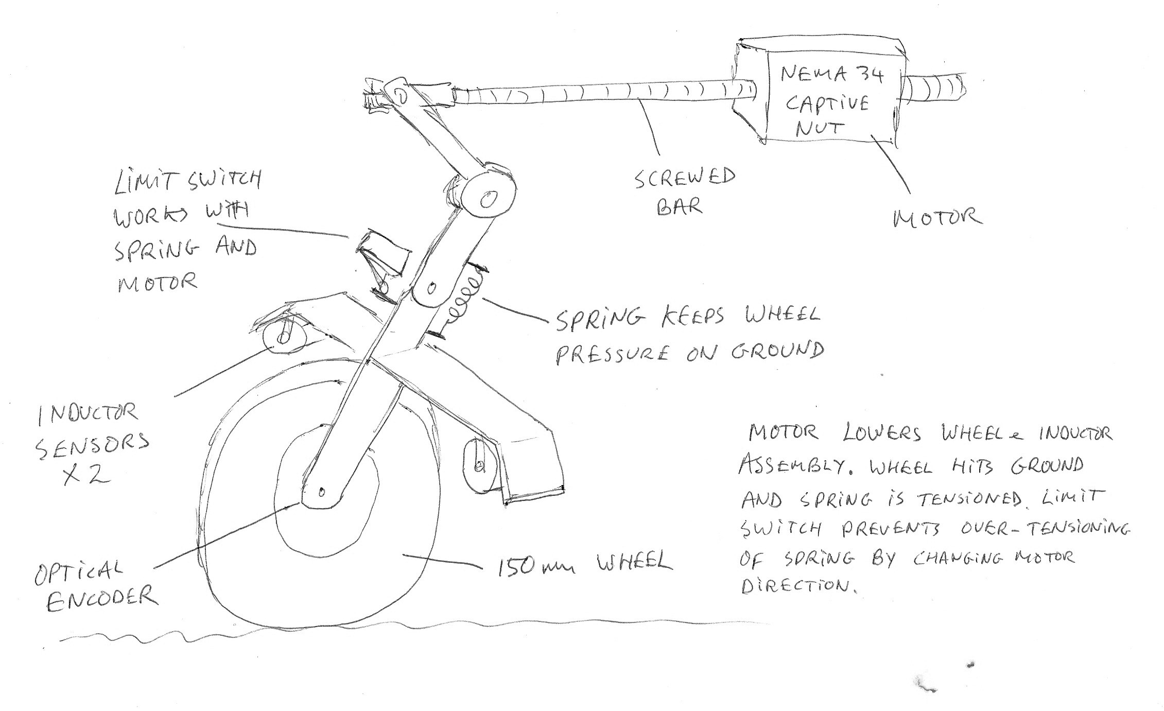
A rotary encoder needs to be incorporated into the design and the drawing below shows my proposed solution which also solves the problem of regulating the height of the encoder bar. This was thought to be easier than trying to retro-fit the encoder into the wheel drive gearbox and has the advantage that there won't be any problem with backlash and there will be more accuracy due to the smaller size of the wheel.
![]() I've got a spare NEMA 34 captive motor lying around in the workshop which acts on a pivot lowering and raising the rest of the assembly. A second pivot a bit lower down enables the wheel to be pressed with constant pressure down onto the ground, with the limit switch constantly changing the direction of the motor whilst the system is in use. If the wheel hits an obstacle such as a stone, the main spring absorbs the extra travel, as does the springy limit switch lever. Another solution would be to put a strain gauge sensor on the spring, but I think this would be over complicated - better to just expend a few watts in the motor.
I've got a spare NEMA 34 captive motor lying around in the workshop which acts on a pivot lowering and raising the rest of the assembly. A second pivot a bit lower down enables the wheel to be pressed with constant pressure down onto the ground, with the limit switch constantly changing the direction of the motor whilst the system is in use. If the wheel hits an obstacle such as a stone, the main spring absorbs the extra travel, as does the springy limit switch lever. Another solution would be to put a strain gauge sensor on the spring, but I think this would be over complicated - better to just expend a few watts in the motor. -
Wire Following Test in Workshop
08/21/2018 at 12:34 • 0 commentsI replaced the inductors in the Robot Shop wire following kit with the following:
Murata 10 mH ±10% Bobbin Inductor, Max SRF:200kHz, Q:48, 600mA Idc, 2.294Ω Rdc 1400
and swapped out the 22nF capacitor with one of 2.2nF. The results were much more uniform!
The new inductors have a lot less resistance and should be much more sensitive and be able to pick up the wire from a greater distance away from it. Maximum distance with reception was measured as being 300mm so I positioned the inductor bobbins at 150mm to get nice reliable results:
The screenshot below shows the wire positioned about 30mm to one side of centre:
![]() … and the oscilloscope shows the red waveform being slightly higher than the blue. On the right hand panel is the Arduino serial out console and this shows a 'reasonable' steady differential of about 80 units out of a total range of 1024 units. This should give enough resolution for the machine to navigate to the required target of +- 5mm.
… and the oscilloscope shows the red waveform being slightly higher than the blue. On the right hand panel is the Arduino serial out console and this shows a 'reasonable' steady differential of about 80 units out of a total range of 1024 units. This should give enough resolution for the machine to navigate to the required target of +- 5mm. -
Code Restructuring
08/20/2018 at 18:08 • 0 commentsOccasionally things get so messy that a tidy up simply can no longer be avoided. So it is true with writing code and having all the code located in one tab makes it difficult to find bits that need tweeking. The Arduino IDE allows code to be split over many different tabs, or columns, as below:
![]()
The trick to do this is to use the 'extern' function to make integers etc global and not just restricted to the code in the tab. And here is an animation to show how it is used:
![]()
The full set of code files are updated regularly on GitHub HERE.
-
Exploring Inductance sensor + Wire Navigation
08/18/2018 at 10:52 • 0 commentsCommonly used to guide automatic lawn mowers, a cable carrying an AC frequency could also possibly guide the WEEDINATOR. This would have a few advantages over using a camera as there would be no problem in very bright sunlight and it would not matter if the cable became slightly covered with soil.
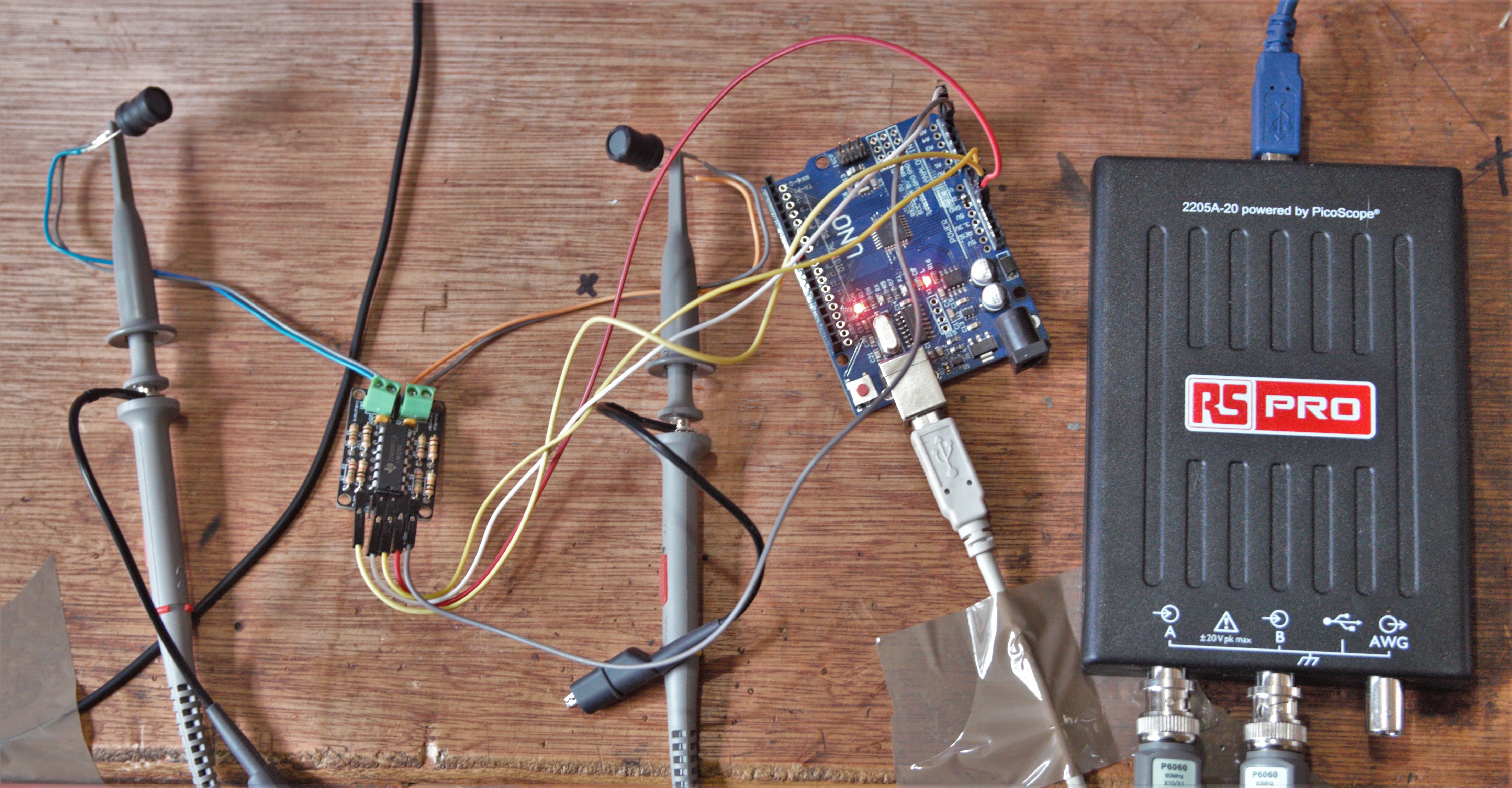
To get started, I bought an incredibly cheap $9 kit from Robotshop and put together a test rig with an oscilloscope from RS supplies:
![]() For the price of the kit, the results were pretty good, but I soon realised that I'd need something a bit better for guiding this machine.
For the price of the kit, the results were pretty good, but I soon realised that I'd need something a bit better for guiding this machine. On the frequency generator board there is a variable resistor that changes the output frequency to match the receiver board and the 'ideal' calculated frequency is 33.932 kHz., but my receiver worked best at 36 kHz:
![]() I wondered why I was getting much better sensitivity on the red channel than the blue and at first suspected the paralleled inductor / capacitor combinations. To test this, I moved the inductors relative to the transmitting wire to balance out the response and adjusted the frequency on the generator board backwards and forwards from a centre of 36 kHz as shown below:
I wondered why I was getting much better sensitivity on the red channel than the blue and at first suspected the paralleled inductor / capacitor combinations. To test this, I moved the inductors relative to the transmitting wire to balance out the response and adjusted the frequency on the generator board backwards and forwards from a centre of 36 kHz as shown below:![]() The difference between the two channels did not change that much, so the LC bandpass filters actually seem to be quite well matched. Since the oscilloscope probes are on the inductors, the problem must be resistance in the inductors or the cables / soldered joints connecting them? Maybe a faulty inductor?
The difference between the two channels did not change that much, so the LC bandpass filters actually seem to be quite well matched. Since the oscilloscope probes are on the inductors, the problem must be resistance in the inductors or the cables / soldered joints connecting them? Maybe a faulty inductor? -
Drive Motor Upgrade - Ampflow A28-400-F48 with VEX Victor BB Driver
08/04/2018 at 16:45 • 7 commentsA while back, I made myself a promise that as soon as enough USD had accumulated in my PayPal account I would upgrade the drive motors. So, using the $2000 odd seed funding from the Hackaday prize and some advertising income from one of my other websites, I made the plunge and ordered those crazy expensive Ampflow motors shown in a previous log. The motors are used by large combat robots for TV shows and don't have optical encoders and positioning control, which, I think, will be an advantage as I have already proven that I can balance the torques on the left and right drive motors using current sensors. The motors themselves (A28-400-F48) are brushed, high torque, high current DC devices with expensive neodymium magnets and a staggering 9.1 Hp at 200 amps for help with manoeuvring over rough ground. They are fan cooled, but will they get hot? Will the VEX Victor BB controller box get hot? Will the motor mounting bolts shear? ….. It's all very risky, but we all got to take risks when the odds are ok and we can afford, both financially and emotionally, to lose.
![]() Firstly, the motors need to have adapter plates made and adapter collars for the shafts to fit the drive gearboxes. These are currently being manufactured so will be shown in the next log.
Firstly, the motors need to have adapter plates made and adapter collars for the shafts to fit the drive gearboxes. These are currently being manufactured so will be shown in the next log.![]() Next, the motors and drivers boxes are set up on a bench and tested using the proprietary VEX software with a Prolific USB to serial cable. Once I'd got a genuine cable from a reputable supplier, the software ran very easily and I was able to make the motors run in no time.
Next, the motors and drivers boxes are set up on a bench and tested using the proprietary VEX software with a Prolific USB to serial cable. Once I'd got a genuine cable from a reputable supplier, the software ran very easily and I was able to make the motors run in no time. ![]() I was a bit concerned about how to control the motors using an MCU, but Alex at VEX's technical support soon put me on the right track. The signal that the Victor BB requires is not a straightforward PWM, but rather an 'asynchronous' PWM where the LOW part of the waveform must be 20ms long. The duration of the HIGH's gives the motor speed and a HIGH of duration 1.0 ms gives full speed forwards, 2.0 ms gives full speed backwards and 1.48 gives neutral ….. Simples!
I was a bit concerned about how to control the motors using an MCU, but Alex at VEX's technical support soon put me on the right track. The signal that the Victor BB requires is not a straightforward PWM, but rather an 'asynchronous' PWM where the LOW part of the waveform must be 20ms long. The duration of the HIGH's gives the motor speed and a HIGH of duration 1.0 ms gives full speed forwards, 2.0 ms gives full speed backwards and 1.48 gives neutral ….. Simples!![]() The VEX Victor BB driver box is wired to an Arduino Uno for testing and the wiring is as below:
The VEX Victor BB driver box is wired to an Arduino Uno for testing and the wiring is as below:![]()
It would be possible to code the Arduino with two delay() functions:
digitalWrite(13,LOW);
delayMicroseconds(20000);
digitalWrite(13,HIGH);
delayMicroseconds(1400);
But that's no use in my TC275 code as delay cannot be used as it will screw up all the other motor timings. Instead, asynchronous motor timing is done with the micros() function. The code was run with an LED and serial print console at very low speed to check that the asynchronous ratios were correct. Serial must be removed, as shown, when running the code at high speed.
// Asynchronous timer float speedTimerA = 0.001; float speedTimerB = 0.001; int LEDState = HIGH; unsigned long previousMicrosTimerA = 0; unsigned long previousMicrosTimerB = 0; unsigned long intervalTimerA = 0; unsigned long intervalTimerB = 0; int count =0; void setup() { Serial.begin(9600); pinMode(13, OUTPUT); // LED pinMode(3, OUTPUT); // motor delay(5000); } void loop() { motor(); //printOut(); // Remove this when using at high speed } /////////////////////////////////////////////////// void motor() { unsigned long currentMicros = micros(); ///////////////////////////////////////////////////// speedTimerA = 650; // Between 1000 and 500. Neutral is 675. intervalTimerA = 1000000/speedTimerA; speedTimerB = 50; // B MUST be slower than A. Speed of 50 Hz == 20 ms. intervalTimerB = 1000000/speedTimerB; intervalTimerB = intervalTimerB + intervalTimerA; count++; if ((currentMicros - previousMicrosTimerA) >= intervalTimerA) { previousMicrosTimerA = currentMicros; if(LEDState == HIGH) { count =0; // Count was used to help prove the maths worked ok. } LEDState = LOW; if ((currentMicros - previousMicrosTimerB) >= intervalTimerB) { LEDState = HIGH; count =0; previousMicrosTimerB = currentMicros; } digitalWrite(13,LEDState); digitalWrite(3,LEDState); } } // motor void printOut() { unsigned long currentMicros = micros(); Serial.print(" Count: ");Serial.print(count); Serial.print(" LEDState: ");Serial.print(LEDState); Serial.print(" TimerA: "); Serial.print(currentMicros - previousMicrosTimerA); Serial.print(" TimerB: "); Serial.println(currentMicros - previousMicrosTimerB); delay(1000); } -
Fully Autonomous Weedings
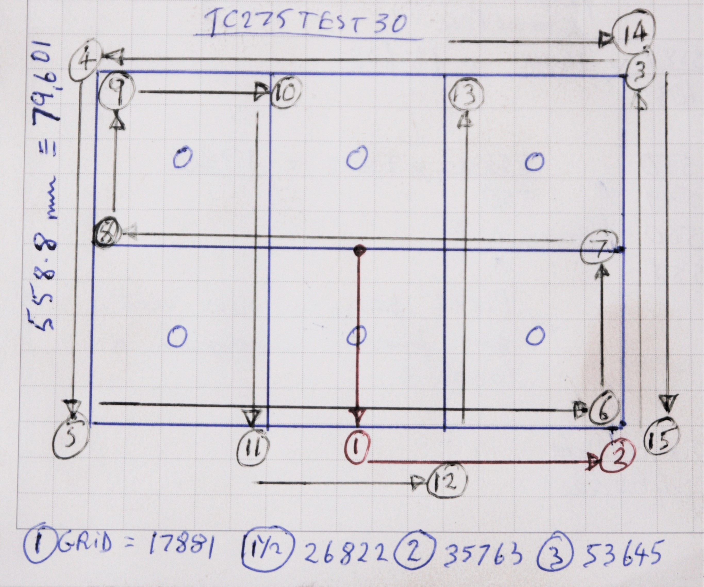
07/21/2018 at 17:22 • 0 commentsFinally ……. After one whole year of work ….. We have autonomous weeding. Actually the machine can now navigate through a series of waypoints using super accurate error correcting 'RTK' GPS and, additionally, it can now navigate along a bed of seedlings and weed the bed with a rotating claw to an accuracy of about +- 5mm. Navigation on the bed itself uses a line following camera - the Pixy2 as even the very best GPS can't navigate to the accuracy that we need to avoid killing the plants.
![]()
The CNC claw is programmed to move in the pattern shown above, weeding two rows of seedlings every time the machine stops. Some of the code can be seen in the previous log. When the claw reaches position 15, the whole machine moves slowly forwards with the claw still weeding, following a white rope, until it reaches a barcode. Then, when the Pixy2 sees the barcode move to a certain point in the it's field of view, it stops the machine dead and tells the CNC to do another circuit. Full details of the code can be seen here.
So what's next? This certainly is not the end of the project as, apart from anything else, there are a few annoying bugs to fix and the drive motors used are either not set up correctly or simply not appropriate ….. If only I could bypass the positioning feature of the motor drivers when the machine is driving up paths etc. …… They're great on the beds of seedlings though.
In terms of the mechanics of the machine, the next stage would be to start thinking about performing another task such as planting. This is actually probably more challenging than weeding, although sowing seeds would be easy enough. Seedlings are a different matter as they are in plugs of compost with roots and stems. The CNC mechanism can perform planting seedlings with the weeding claw apparatus swapped out for a different device ….. Who knows what that will look like?
In reality, there's quite a bit of work to do on the control system. The original aim of the project was to try and use advanced Ai based object detection to help with navigation and this now seems to be very much more realistic. Now that the vegetable season here has pretty much finished, the main focus of the project has switched to working on the Jetson TX2 Ai platform to enable plant recognition.
-
Testing Automated CNC in the Field on a Crop of Leeks
07/17/2018 at 19:10 • 0 comments -
CNC Automation Demo
07/14/2018 at 14:26 • 0 commentsAnother project milestone has been reached ….. The CNC mechanism is now automated and a few hundred lines of code written to perform a basic demonstration of all the servo motors running simultaneously. No special servo library is used, which makes coding easier as everything is low level and there's no restriction in the number of channels or 'special' tasks like 'pause' or 'wait until X axis has reached end point' ………. I'm very pleased with how it's worked out and there's still plenty of memory left on the TC275 MCU to write a nice little algorithm for performing an actual weeding routine.
The next stage is to put a current sensor on the rotating claw driver power supply. This will limit the amount of work that the claw does, which itself depends on soil conditions and the depth that the claw is working at. This way, no expensive LIDAR or radar is required and there *should* not be any problem with accuracy and missing any patches of low lying soil - the soil levels are not dead flat, particularly after the tractor has just been over it.
-
More Test Beds Planted
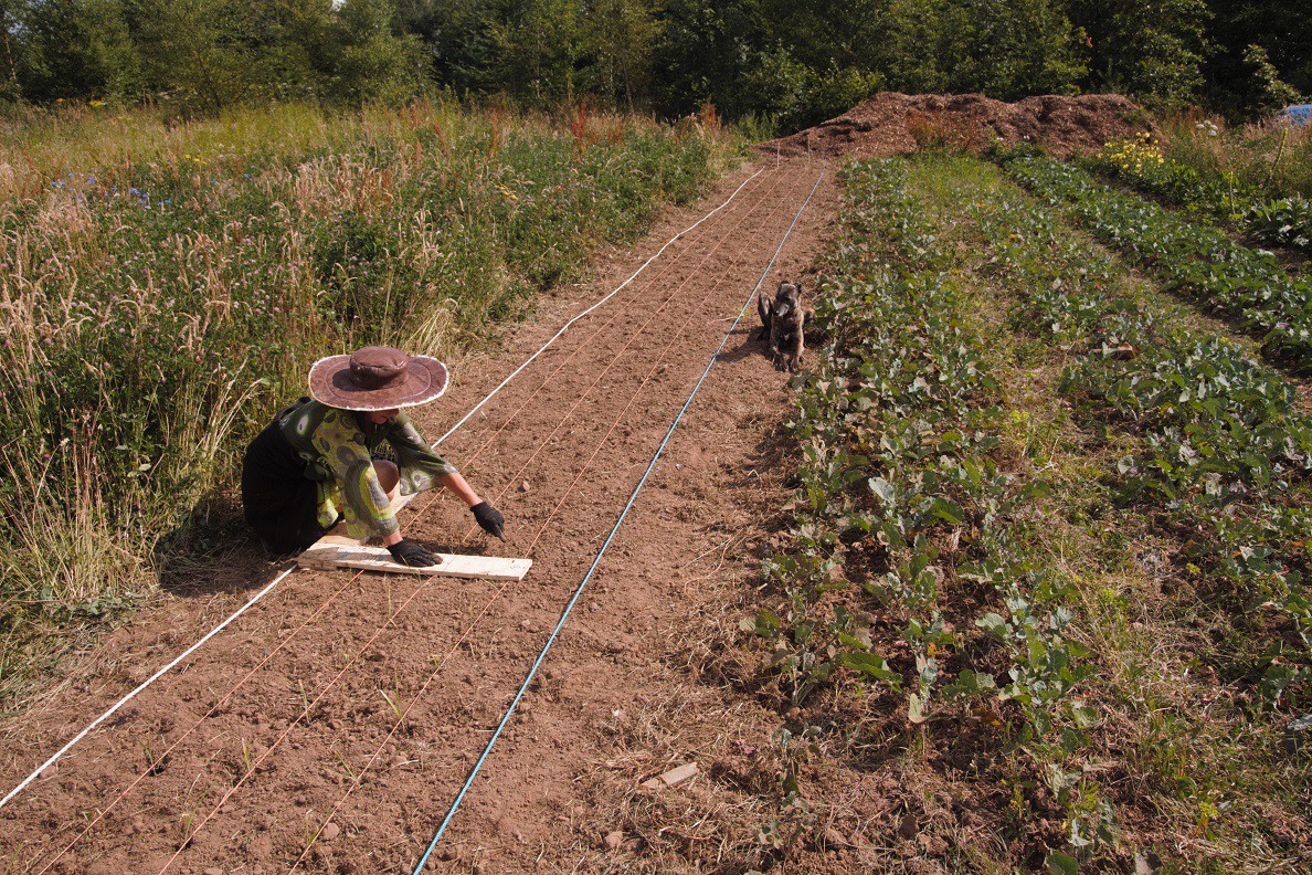
07/12/2018 at 09:51 • 0 comments![]() The farm dog has a particularly good eye for precision and will spot any leek that's out of place! ….. Precision is really important for testing the machine and the plants themselves need to be in exactly the right place. Ultimately, maybe next year, the machine will be able to do the planting, but for now we use humans (and dogs).
The farm dog has a particularly good eye for precision and will spot any leek that's out of place! ….. Precision is really important for testing the machine and the plants themselves need to be in exactly the right place. Ultimately, maybe next year, the machine will be able to do the planting, but for now we use humans (and dogs).The white rope on the left will guide the machine with +- 5mm precision and barcodes will be printed out and laid down on the rope where we want the machine to stop and perform a series of weeding operations. Obviously, mud and dirt could be a problem by obscuring the barcodes, but for now everything is bone dry and there would be no problem. Eventually, more advanced cameras will be used and the plants themselves will be used to create a virtual 2D array for use as a navigational aid. In this case, the white rope will remain, but the barcodes method can be discarded and we'd revert to GPS instead ….. Well that's the plan anyway!
WEEDINATOR 2019
The WEEDINATOR project continues .... The inevitability of robots working on farms draws ever nearer ....
 I've got a spare NEMA 34 captive motor lying around in the workshop which acts on a pivot lowering and raising the rest of the assembly. A second pivot a bit lower down enables the wheel to be pressed with constant pressure down onto the ground, with the limit switch constantly changing the direction of the motor whilst the system is in use. If the wheel hits an obstacle such as a stone, the main spring absorbs the extra travel, as does the springy limit switch lever. Another solution would be to put a strain gauge sensor on the spring, but I think this would be over complicated - better to just expend a few watts in the motor.
 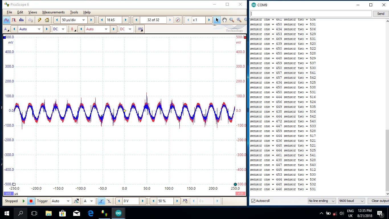 … and the oscilloscope shows the red waveform being slightly higher than the blue. On the right hand panel is the Arduino serial out console and this shows a 'reasonable' steady differential of about 80 units out of a total range of 1024 units. This should give enough resolution for the machine to navigate to the required target of +- 5mm.
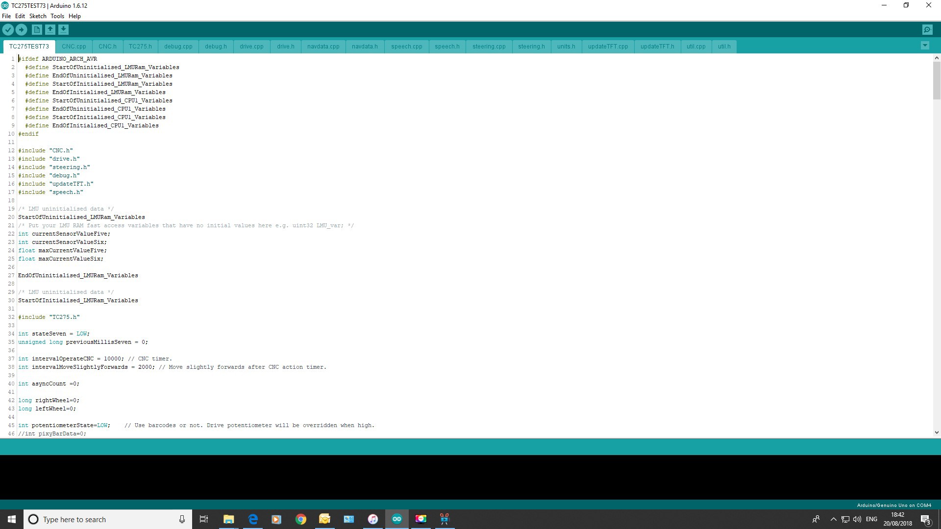
 For the price of the kit, the results were pretty good, but I soon realised that I'd need something a bit better for guiding this machine.
 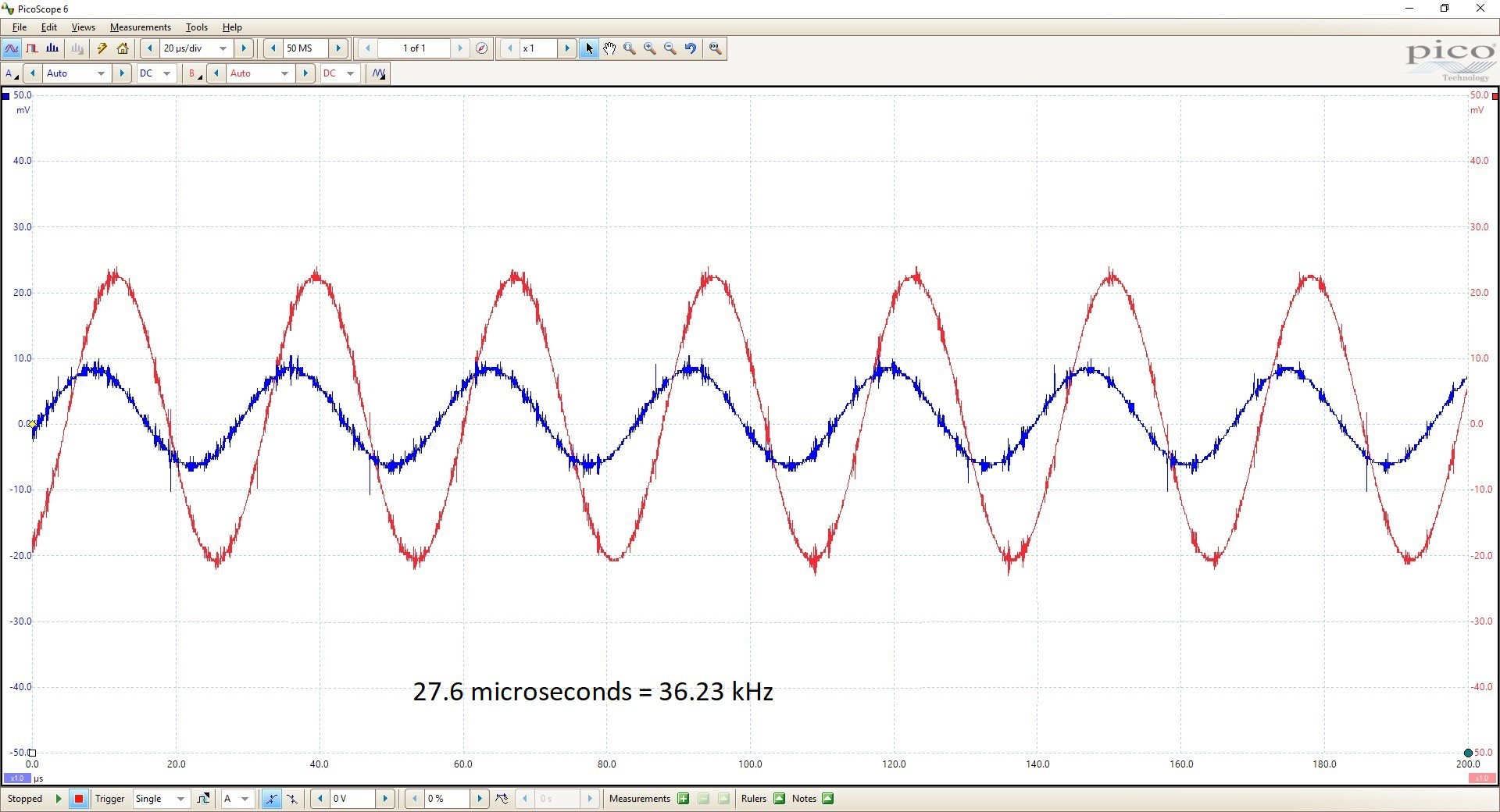 I wondered why I was getting much better sensitivity on the red channel than the blue and at first suspected the paralleled inductor / capacitor combinations. To test this, I moved the inductors relative to the transmitting wire to balance out the response and adjusted the frequency on the generator board backwards and forwards from a centre of 36 kHz as shown below:
 The difference between the two channels did not change that much, so the LC bandpass filters actually seem to be quite well matched. Since the oscilloscope probes are on the inductors, the problem must be resistance in the inductors or the cables / soldered joints connecting them? Maybe a faulty inductor?
 Firstly, the motors need to have adapter plates made and adapter collars for the shafts to fit the drive gearboxes. These are currently being manufactured so will be shown in the next log.
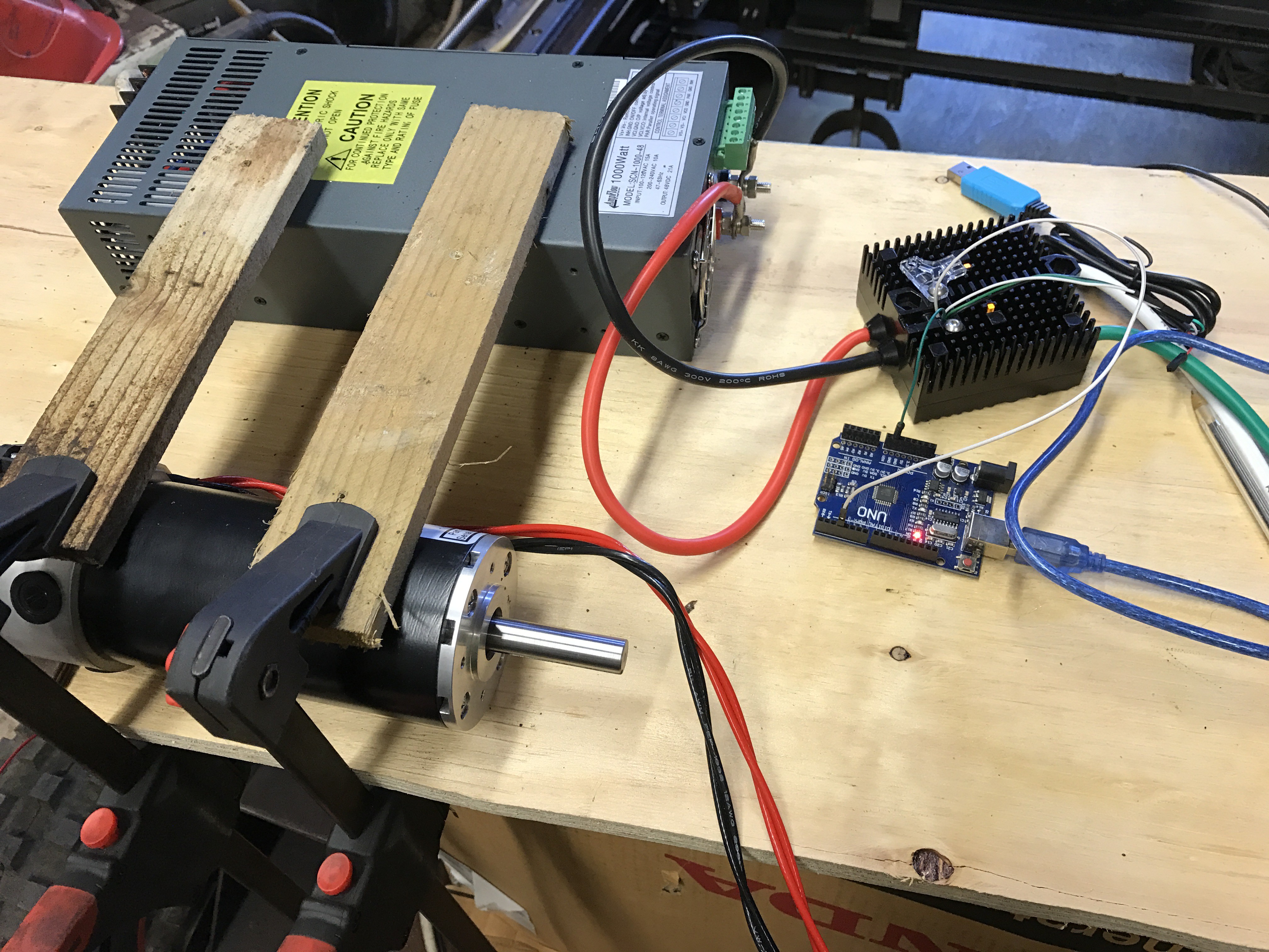 Next, the motors and drivers boxes are set up on a bench and tested using the proprietary VEX software with a Prolific USB to serial cable. Once I'd got a genuine cable from a reputable supplier, the software ran very easily and I was able to make the motors run in no time.
 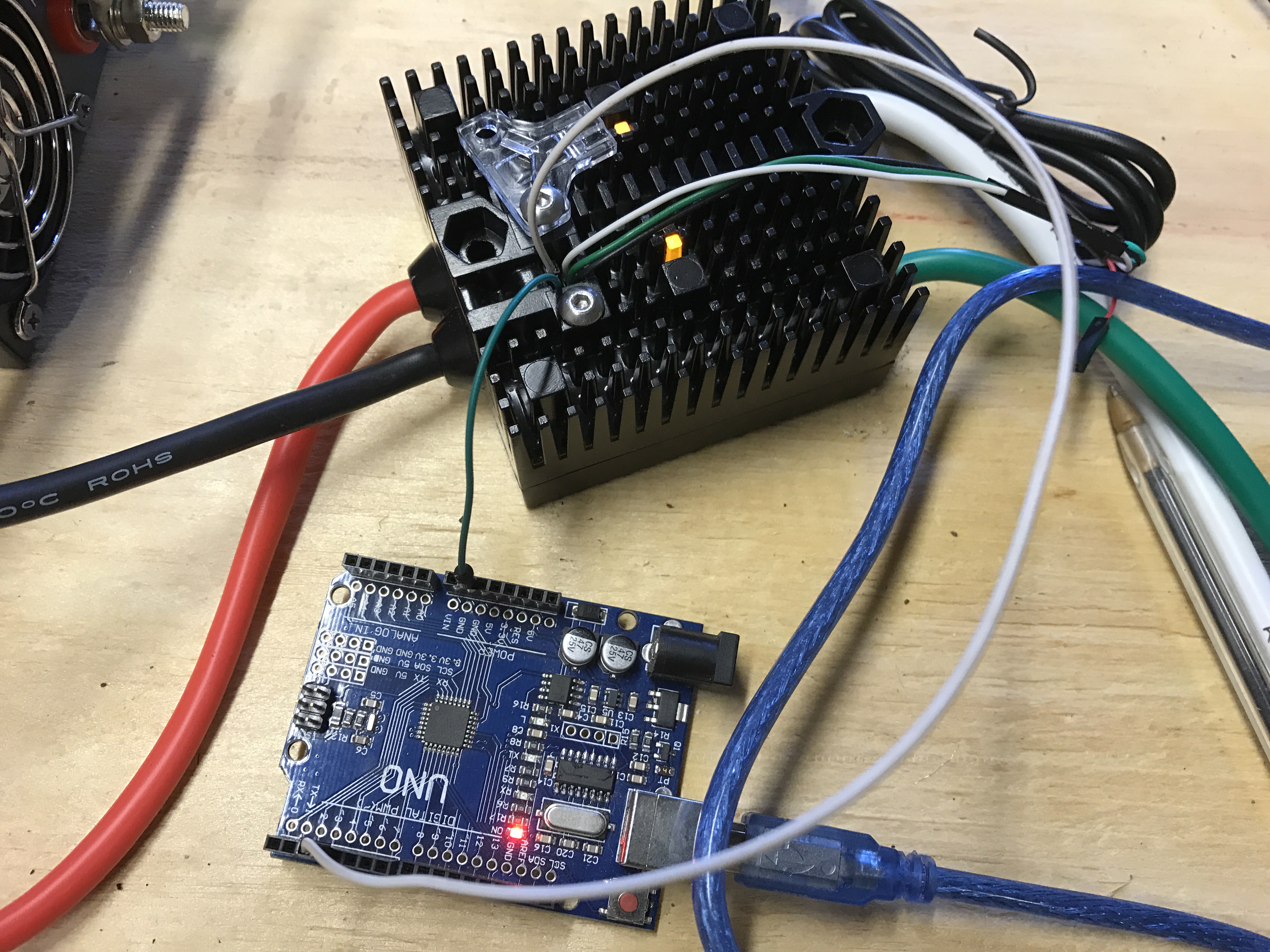 I was a bit concerned about how to control the motors using an MCU, but Alex at VEX's technical support soon put me on the right track. The signal that the Victor BB requires is not a straightforward PWM, but rather an 'asynchronous' PWM where the LOW part of the waveform must be 20ms long. The duration of the HIGH's gives the motor speed and a HIGH of duration 1.0 ms gives full speed forwards, 2.0 ms gives full speed backwards and 1.48 gives neutral ….. Simples!
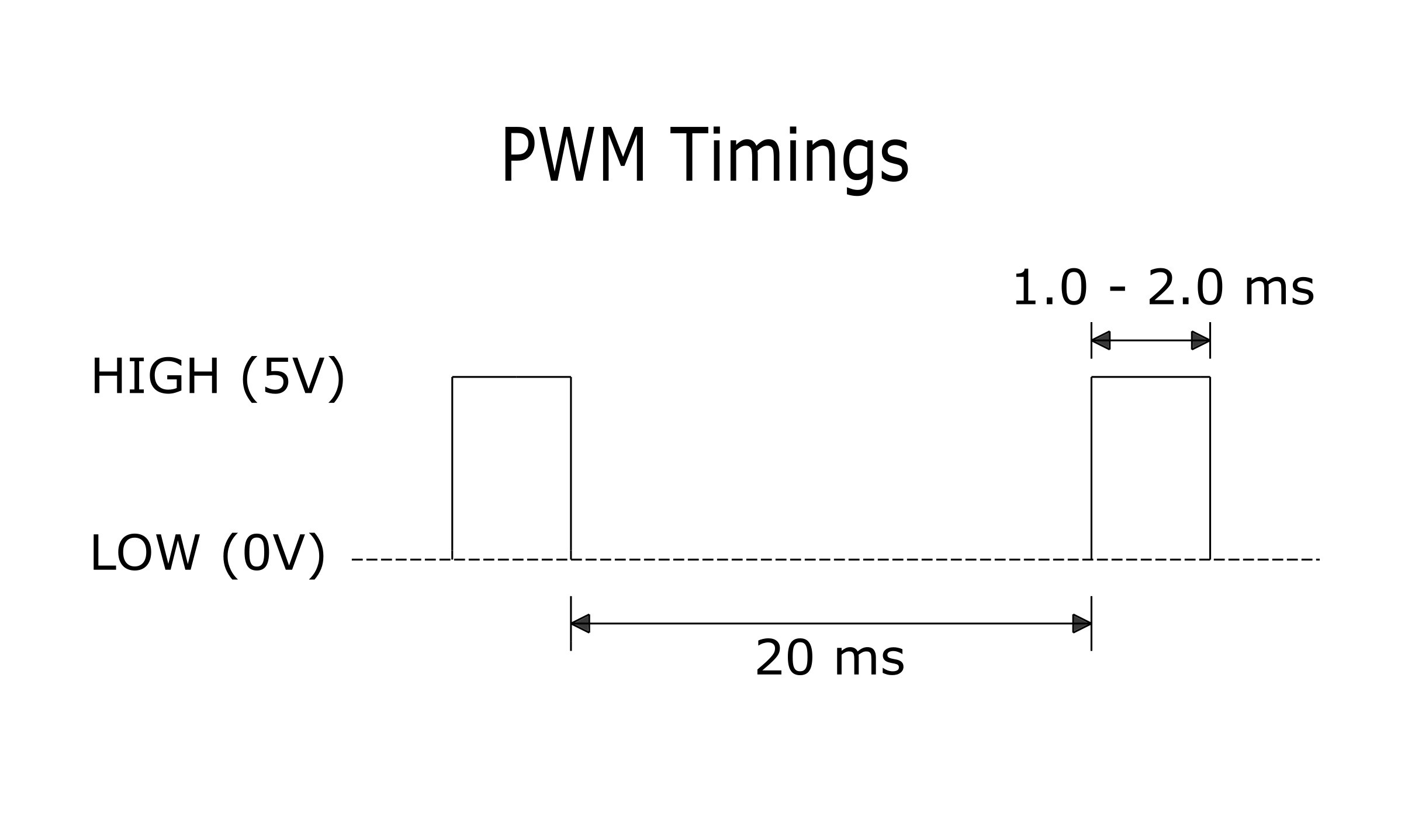 The VEX Victor BB driver box is wired to an Arduino Uno for testing and the wiring is as below:
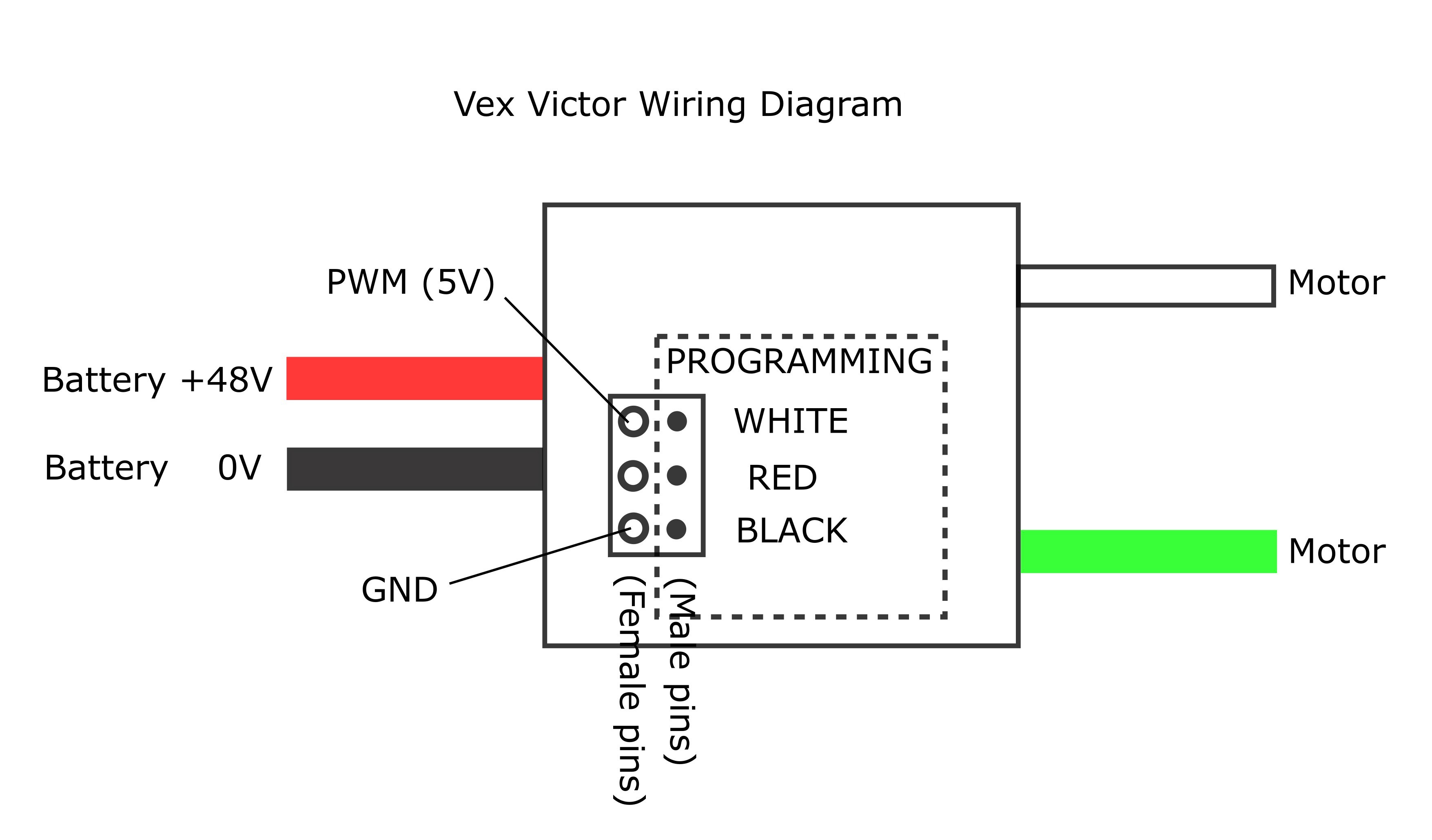
 The farm dog has a particularly good eye for precision and will spot any leek that's out of place! ….. Precision is really important for testing the machine and the plants themselves need to be in exactly the right place. Ultimately, maybe next year, the machine will be able to do the planting, but for now we use humans (and dogs).