• Controlling a Seeed Motor Shield with an ATtiny85 and Shift Registers

    C. Parkin05/13/2015 at 16:35 0 comments

    In addition to a handful of TV-B-Gone kits, the feeding frenzy at Radioshack also yielded a dozen SeeedStudio Motor Shield V2.0 boards for a few bucks a piece. They aren't ordinarily the easiest, cheapest, or anything close to the best way of driving motors, but I had them already, so it seemed like the avenue to explore for the next phase of this project.

    What I discovered, upon investigating their usage, is that these motor shields seems to be pieces of junk compared to the others on the market. The documentation available is especially poor, and in hours of scouring the web, I could find very, very few instances of anyone successfully using the buggers.

    However, based on cryptic, incomplete official documentation and what few implementation examples I could find, it seemed to me that they should, in principle, be simple to use, even without getting my Arduino out of the box.

    Happily, after a protracted struggle, I found this to be true.

    Here are the pins of importance:

    Pin 8: Motor A Control Line 1 (IN1)
    Pin 11: Motor A Control Line 2 (IN2)
    Pin 9: Motor A Speed Control (EA)
    Pin 12: Motor B Control Line 1 (IN3)
    Pin 13: Motor B Control Line 2 (IN4)
    Pin 10: Motor B Speed Control (EB)

    The few examples all show the control line as taking a PWM signal, but looking at the data sheet for the L298 IC (Dual Full-Bridge Driver) which drives the thing, the control line simply appears to be an enable. In any case, a constant 5V signal should equate to a 100% duty cycle PWM signal, so one can enable the motor with a simple logical HIGH (which is important as I'm using a shift register to drive the thing).

    Very simply (as derived from the "official" Github example), for each motor:

    Enable (EN)

    Input1 (IN1)

    Input2 (IN2)

    Function

    H

    L

    H

    Turn CC

    H

    H

    L

    Turn CCW

    H

    L

    L

    Fast Stop

    H

    H

    H

    Fast Stop

    L

    X

    X

    Fast Stop

    I managed (with help from an EE of my acquaintance) to wire up a simple set of switches to confirm the control patterns before risking any chips, then set about connecting it to the PISO Shift Register --> ATtiny85 --> SIPO Shift Register (P.A.T.S.) circuitry described in the last project log.

    The "behavior" pattern that I wanted the first version of the One-Tiny Bot to exhibit is simple: proceed forward, with two "whisker" switches to the front left and right. If the left switch is pressed, stop, back up, turn right, and proceed. If the right switch is pressed, stop, back up, turn left, and proceed. If both are pressed, stop, back up, turn around, and proceed.

    Extending the program for illuminating LEDs based on DIP switch input to controlling motors was relatively straightforward. Remembering that the bit order (from least-significant) is opposite of the shift register D/Q pin order, this pattern corresponds to the following bytes:

    FORWARD: 101101XX
    STOP: 000000XX
    REVERSE: 110110XX
    RIGHT: 101110XX
    LEFT: 110101XX

    Where the last two bits are not used in motor control.

    Rathering to add functionality rather than remove it, I left the DIP switch in place, and tied in two pull-down pushbuttons to 74HC165 pins 11 (right button) and 12 (left button). Ignoring all other inputs but the last, which I used as an on/off switch, the input byte encoding is:

    (left button)-(right button)-X-X-X-X-X-(ON/OFF)

    A handful of elseif's, and the thing worked like a charm.

    An essential thing to note is that *the control circuitry and the motor shield must have a common ground* in order to avoid a ground potential error in the signaling.

    Here is a poor quality photograph of the setup. Schematic forthcoming, I swear!

    And here's the annotated code:

    // 8xDIP/PUSHBUTTONS --> P.A.T.S. --> SeeedMotorShield/8xLED --> 2 Motors
    // ===========================================================================================
    // Updated 13May2015
    // By C. Parkin
    
    
    // Pins
    int clockPin    = 0;    // *COMMON* connected to pin 11 (SH_CP, SRCLK) of 595, pin 2 (CLK/CP) of 165
    int outLatchPin    = 1;    //connected to pin 12 (ST_CP, RCLK) of 595
    int outDataPin...
    Read more »

  • ​Expanding the ATtiny85's IO Capacity with Shift Registers

    C. Parkin05/06/2015 at 18:44 0 comments

    The ATtiny85 is a great little chip, but decidedly lacking when it comes to IO pins. While excellent mobile robots can certainly be built around its innate capabilities, I decided that I needed to expand beyond 5 pins for the sorts of applications I had in mind. Figuring out different ways to do so has proven wonderfully educational.

    The obvious and easiest place to start was with shift registers, as first suggested to me by the Sparkfun Tiny AVR Programmer Hookup Guide.

    Accordingly, I acquired some 74HC165 (PISO: Parallel-In/Serial-Out) and 74HC595 (SIPO: Serial-In/Parallel-Out) shift register chips, and set about learning how to make the Tiny talk to one, the other, and then both of them.

    There are a plethora of helpful guides on using these chips with Arduino:

    These methods (with the exception of those utilizing the shiftIn() function) transfer easily to the ATtiny85. However, because it lacks sufficient IO pins and built-in SPI support, talking to more than one (non-daisy-chained) shift register at once is not so easy on the smaller chip.

    The solution I found was to share a single clock line between the PISO and SIPO shift registers, with separate latch and data lines for each, holding the various enables and inhibits steady. While this approach has drawbacks, such as requiring firm temporal separation of input and output phases and the need to refresh the SIPO register for each output, it allowed me to easily control the two shift registers with only 5 pins.

    As a first project, I chose to reproduce the setup demonstrated in Sparkfun's introductory Shift Register video, reading the state of an 8-position DIP switch with a 74HC165 and turning on a corresponding bank of 8 LEDs through a 74HC595.

    Here's a photo of the setup (schematic forthcoming soon!):

    And here's the code:

    // 8xDIP --> 74HC165 --> ATtiny85 --> 74HC595 --> 8xLED
    // ====================================================================================
    // Updated 05May2015
    // By C. Parkin
    
    
    // Pins
    int clockPin    = 0;    // *COMMON* connected to pin 11 (SH_CP, SRCLK) of 595, pin 2 (CLK/CP) of 165
    int outLatchPin    = 1;    //connected to pin 12 (ST_CP, RCLK) of 595
    int outDataPin    = 2;    //connected to pin 14 (DS, SER) of 595
    int inLatchPin    = 3;    //connected to pin 1 (SH/LD, PL)("shift/load") of 165
    int inDataPin    = 4;     //connected to pin 9 (QH, Q7) ("data") of 165
    
    // Other Pin Settings:
    // 165: 
    //     Pin 15 (CLK INH or CE) ("clock enable") to GROUND (active low)
    //      Pin 10 (SER, DS) ("serial data input") to GROUND (when not connected to another 165)
    //     Pin 11-14 (A-D), 3-6 (E-H) to parallel inputs
    //    Pin 16 to Vcc
    //    Pin 8 to GND
    //    Pin 7 (Q_H or Q_7) ("complementary output from the last stage") left unconnected?(as shown on 2+ sources)
    //
    // 595:
    //    Pin 10 (MR, SRCLR) ("Master Reset", "Serial Clear") to Vcc
    //    Pin 13 (OE) ("output enable input") to GROUND (active LOW)
    //    Pin 16 to Vcc
    //    Pin 8 to GND
    //    Pin 15, 1-7 to parallel outputs
    //      Pin 9 (Q7") ("Serial out") left unconnected w/only 1 chip?
    
    
    // Serial storage variables
    byte inByte;    //for the 8 values loaded FROM the 165 shift register
    byte outByte;    //for the 8 values loaded TO the 595 shift register


    // function to read in from 165
    
    void getter()
    {
    
        // take the latch pin low to move the parallel inputs into the shift register
        digitalWrite(inLatchPin, LOW);
        delayMicroseconds(5);   //some resources suggest 10 for this; try that if 5 doesn't work.
        digitalWrite(inLatchPin, HIGH);
        
        // populate the inByte
        for (int bitCount = 0; bitCount < 8; bitCount++)
        {
            // set the current bit to the current value of inDataPin
            bitWrite(inByte, bitCount, digitalRead(inDataPin));
    
    ...
    Read more »

  • Resetting the TV-B-Gone's ATtiny85 to Its Internal Clock

    C. Parkin04/30/2015 at 20:28 0 comments

    Being an electronics novice, I chose to program my ATtiny85 with the Sparkfun Tiny AVR Programmer. This device is inexpensive, extremely easy to use, and was designed to play well with High Low Tech's ATtiny Arduino core. The HLT tutorial is excellent, but assumes that you are using an ATtiny in all of its default settings, and fails to explain how to proceed if you are not.

    In particular, an off-the-shelf ATtiny85 runs at 1 MHz according to its internal clock, but in order to attain greater precision, Adafruit's TV-B-Gone kit uses an external 8.00 MHz ceramic oscillator. Simply plugging a Tiny from this kit into the programmer (or hooking it up to an Arduino UNO as also described in the tutorial) will frustratingly fail to work.

    To reset it to its internal clock, you must connect it to the external ceramic resonator provided. I did this by jumping the Programmer's IC breakout pins to the Tiny on a breadboard, and connecting the ceramic resonator's two outside pins to the Tiny's pins 2 (CLKI) and 3 (CLKO), and the center pin to ground.

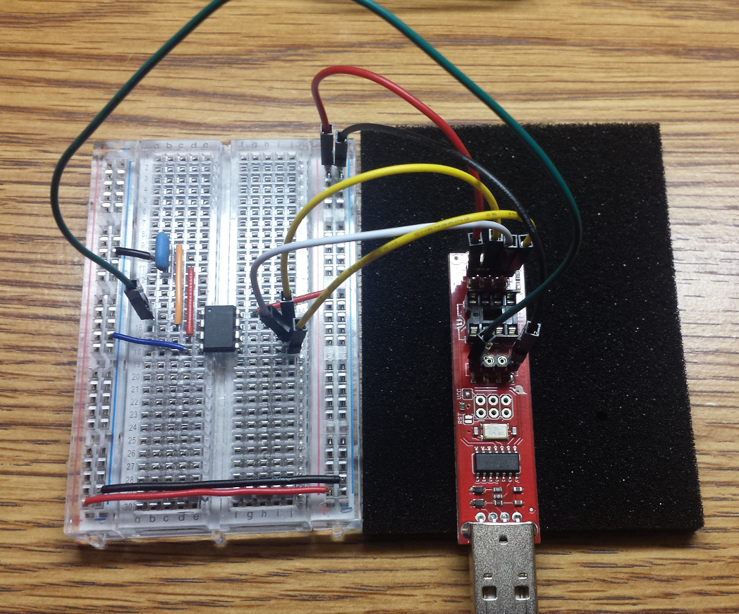
    I could then plug the programmer into my computer, open Arduino, and use the "Burn Bootloader" command from the Tools menu (after first selecting "8 MHz (Internal)" from the Tools > Clock menu) to reconfigure the Tiny to use its internal clock.

    Thenceforth, the Tiny could be programmed directly on the Tiny AVR Programmer without any need for an external setup.