 core weaver
[...] once I've decided to build a GSM platform I had to look for a good GSM module.
I picked the SIM900 GSM Quad Band Module which comes at a very reasonable price and incorporates a lot of features like:
- small sized (only 24x24x3mm)
- GPRS - multislot class 10
- support for 1.8V and 3V simcards
- good TX power (2W for 850/900MHz, 1W for 1800/1900MHz)
- asynchronous full modem with status and control line
- autobauding 1200-115200 bps
- upgradeable firmware
- TCP IP/ PBCC/ FAX/ SMS
- RTC/ Temperature Sensor/ ADC
- low noise, echo cancellation
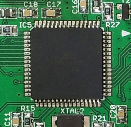
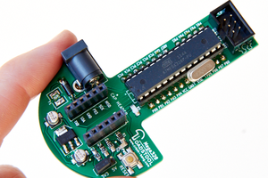
The AVR ATMEGA128 handles all the operations like: sending the AT Commands to the SIM900 module via UART, controlling the 2.8'' /320x240/ Touchscreen Display, setting and reading the current date/time from the dedicated RTC chip (via I2C), detecting all the events signalled by the GSM module (like incoming call, incoming SMS, connection with the network was lost, and so on)..
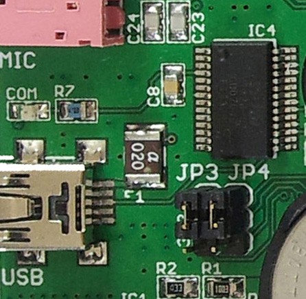
It also communicates with the outside world via USB (onboard dedicated FDTI chip) on it's second UART.
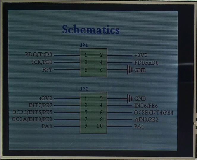
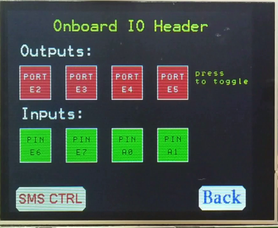
and since I wanted to be able to interface various devices (inputs and outputs) directly with the system, I routed 8x IO lines from the microcontroller to the 10pin connector at the top of the board. ..
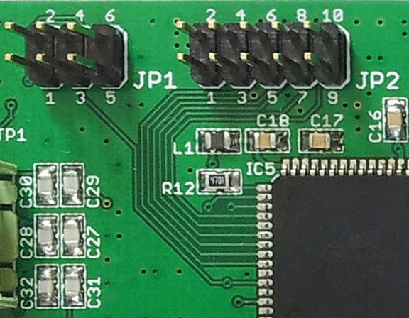
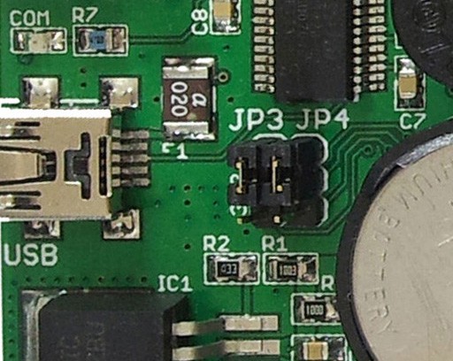
There's also another 6pin header which holds the ISP lines so you can use it to connect your programmer and flash the AVR's firmware. Since the PDI and PDO are also RXD0 and TXD0 on the ATMEGA128 I have the possibility to decide if I currently want to reflash the avr or communicate over USB, by setting two jumpers (JP3 and JP4).
I get very good signal quality using the foldable SMA Antenna which connects with the system also on the top side of the board.
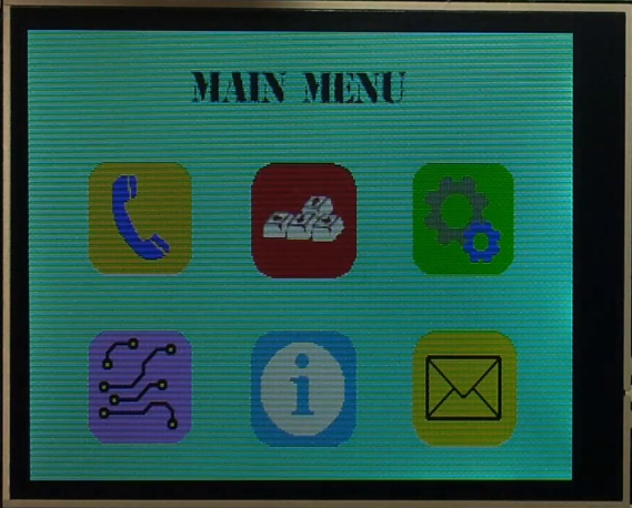
Although the AVR's firmware is implementing a lot of things it's still made as a demonstration tool. I made separate applications and I've put everything together. These applications are accessible from the Main Menu.
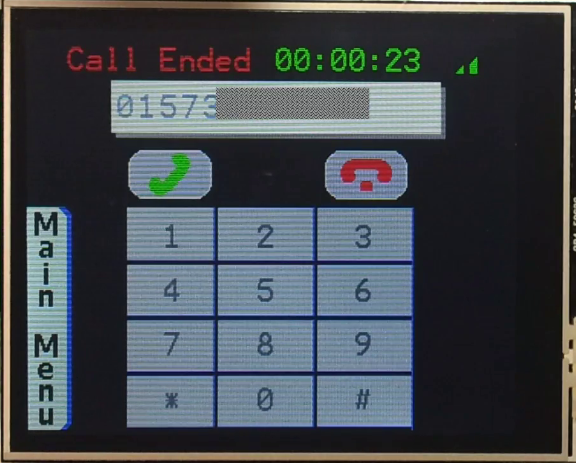
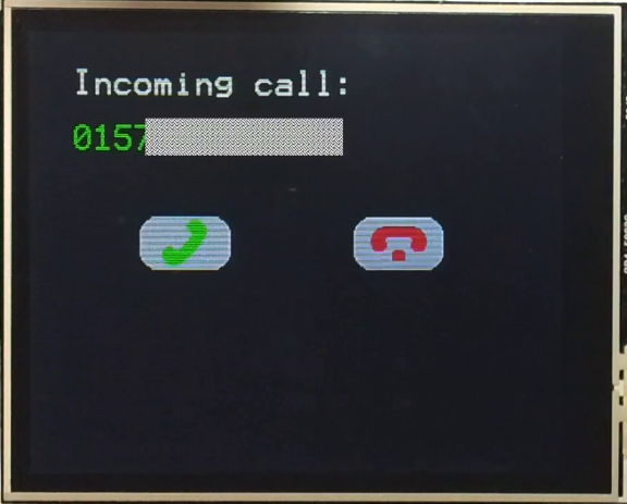
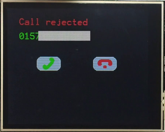
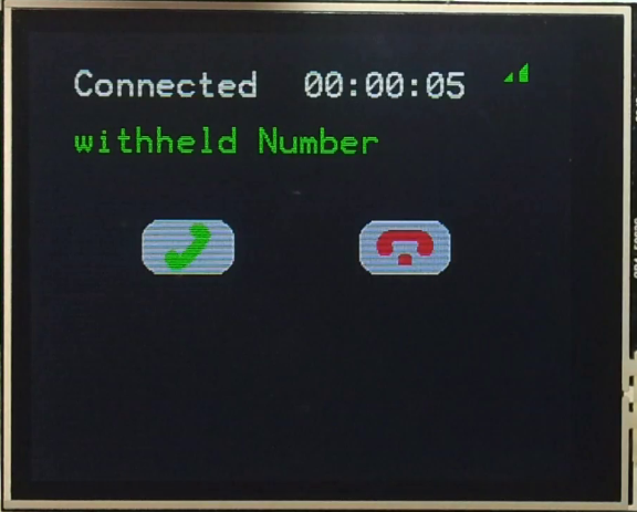
The "Phone function" is basically converting the system into a GSM mobile phone. You can initiate and receive calls the same way you do with a normal cellphone.
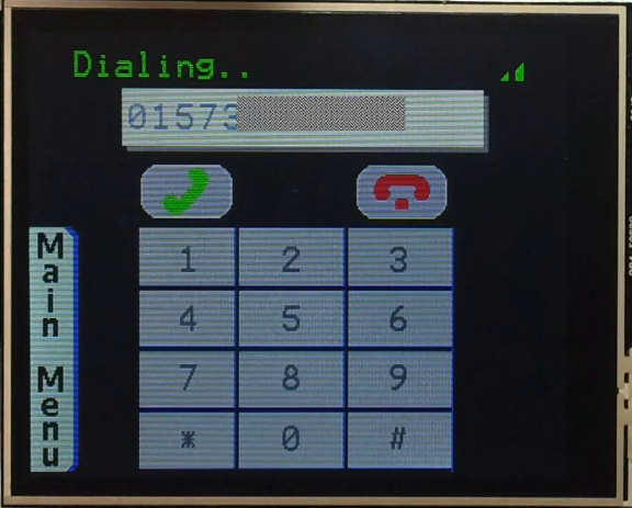
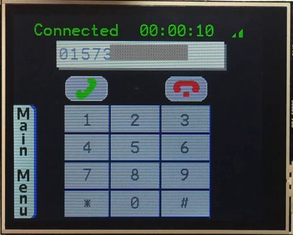
The system detects the caller's ID, monitors call's parameters like duration of the call and signal's strength, and also detects when the call was dropped (busy tone, no network, normally disconnected, no answer...)
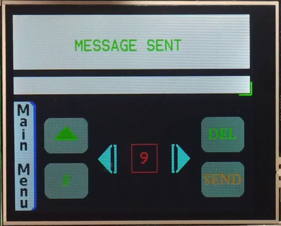
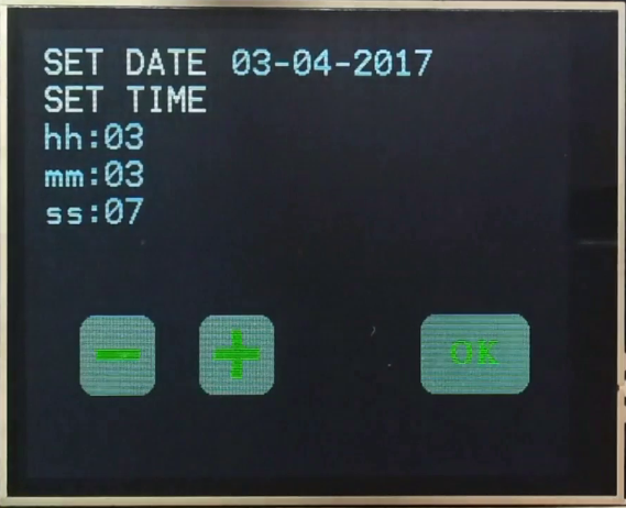
Sending SMS Text Messages: Setting the time and date:
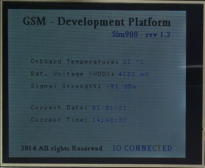
System informations being shown in real time:
I also wanted to be able to enter commands and query the system from my PC. So I designed this handy Terminal. 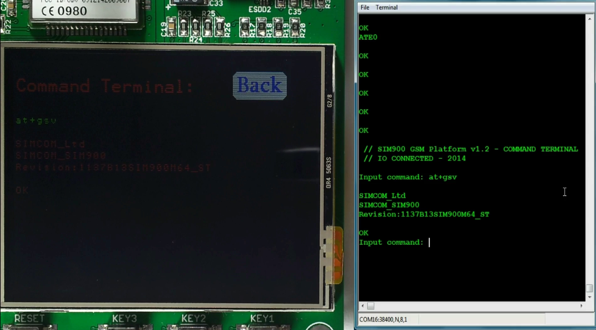
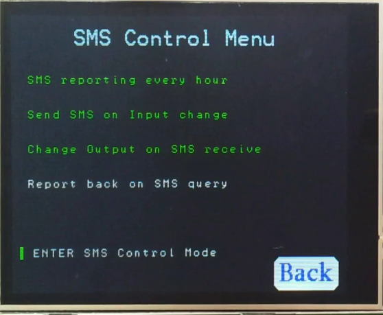
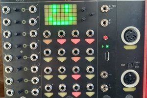
At last the most important thing.. I wanted to control things and read their status from great distances. That was the whole point in building all this.
Different behavior modes: The 8 IO lines: 4 Inputs and 4 Outputs
receiving the Acknowledge on my cellphone, after a command has executed...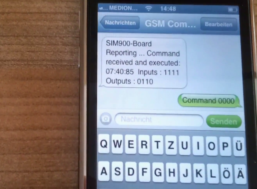
You can watch how everything works in this Youtube video. I also explained a second mode to interface with inputs and outputs on various other boards, everything connected on the same UART.


 Andrew Retallack
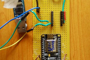
 David
David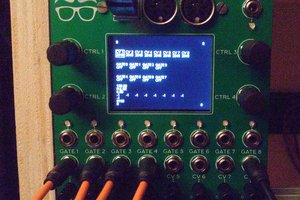
 Michele Perla
How much are you selling this for? Where do I go to buy?