 Bruce Land
Opamp circuits:
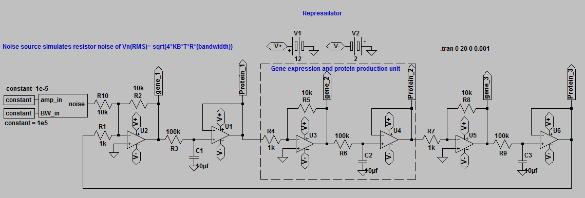
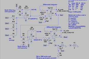
Repressilator: The repressilator
is a genetic oscillator (3). Here we build an electronic approximation
of the repressilator. Gene expression is represented by the output of
opamps U2, U3 and U5 below. Protein concentration is represented by the
output of U1, U4 and U6. If all of the gene representing opamps have
absolute gain greater than 2 (e.g. -R2/R1) then the system oscillates.
The RC circuits (e.g. R3C1) represent the time constant of
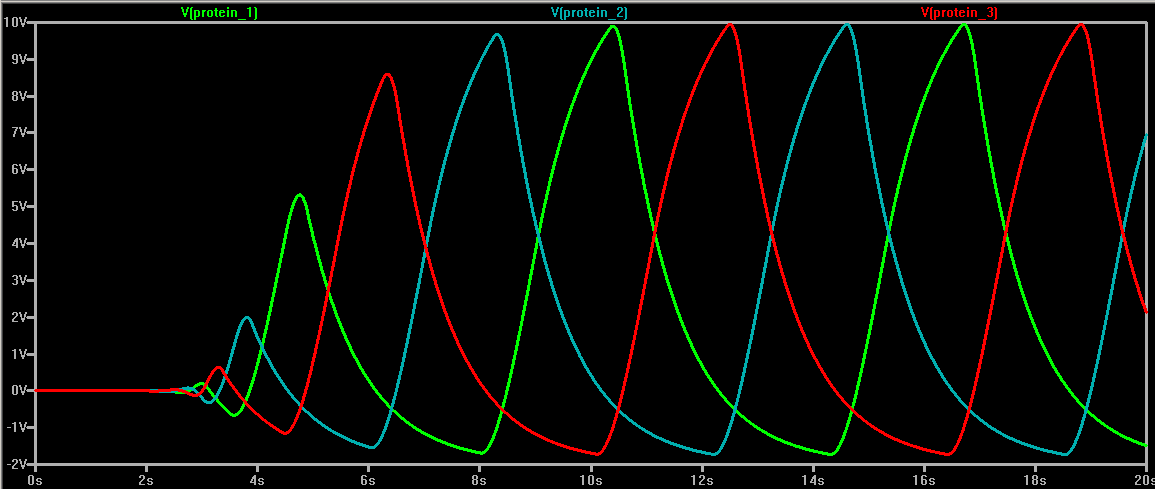
production/degradation of protein. LTspice model, which requires the constant module and the noise module
explained below. In a real circuit the noise module is not necessary
because real resistors are noisy, and so the oscillator starts up
quickly. In the simulation, the oscillator can enter a metastable state
for a long time until numerical error starts the oscillation.
Filters:
Neural models:
See also a hardware neurons page I generated in 2005.
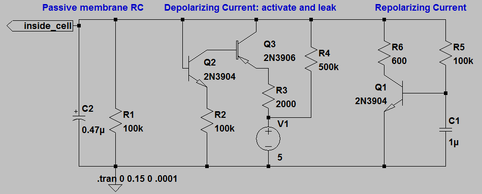
FHN: Maeda and Makino (1) show how to model a neuron
using 3 transistors for a FitzHugh-Nagumo (FHN) type neuron
(simplified from Hodgkin-Huxley formulation). The FitzHugh-Nagumo
scheme replaces the fast Na current of the HH model with a simplified
fast, depolarizing, activation process, and replaces the slow Na
inactivation and slow, repolarizing, K current by a single slow
inactivation process. The circuit is show below for the FHN neuron. The
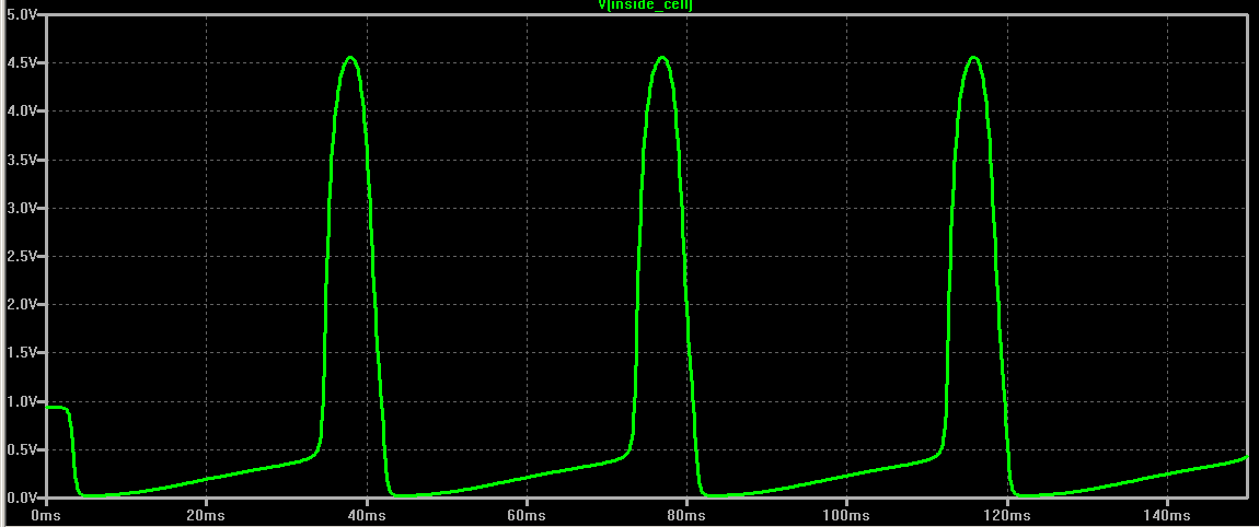
circuit produces a constant train of simulated action potentials (AP)
when a leak current is applied via R4. Note that the amplitude of
the simulated action potential is much larger than that of a
physiological neuron. Simulated AP amplitude is around 5 volts, while
in real life the AP amplitude is around 100 mV. LTspice model.
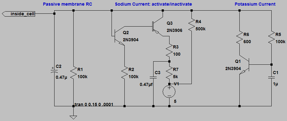
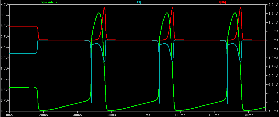
Adding inactivation: A modification of Maeda and
Makino (1) circuit simulates sodium inactvation. Below, the cyan trace
is sodium current and the red trace potassium current. LTspice model.
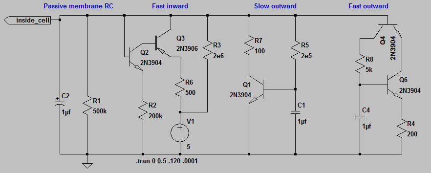
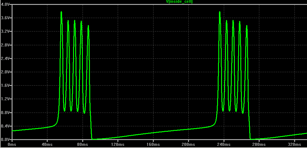
Bursting: By adding one more repolarizing
process, modeled by two more transistors, Maeda and Makino (1) can
produce a neuron with bursting behavior. LTspice model.
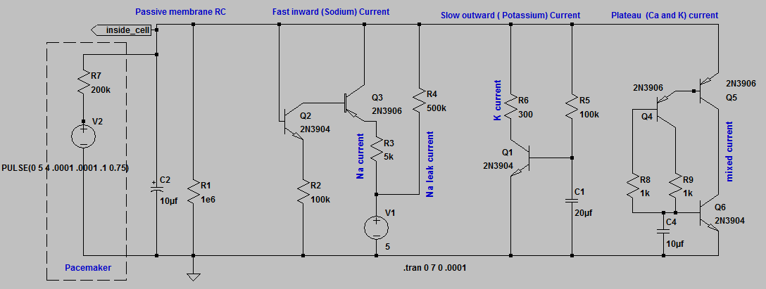
Heart cell: Maeda, Yagi, and Makino (2) extend the
model to include heart cells. They slightly modified one of the
repolarizing processes to make a plateau potential, similar to that
found in a ventricle cell.
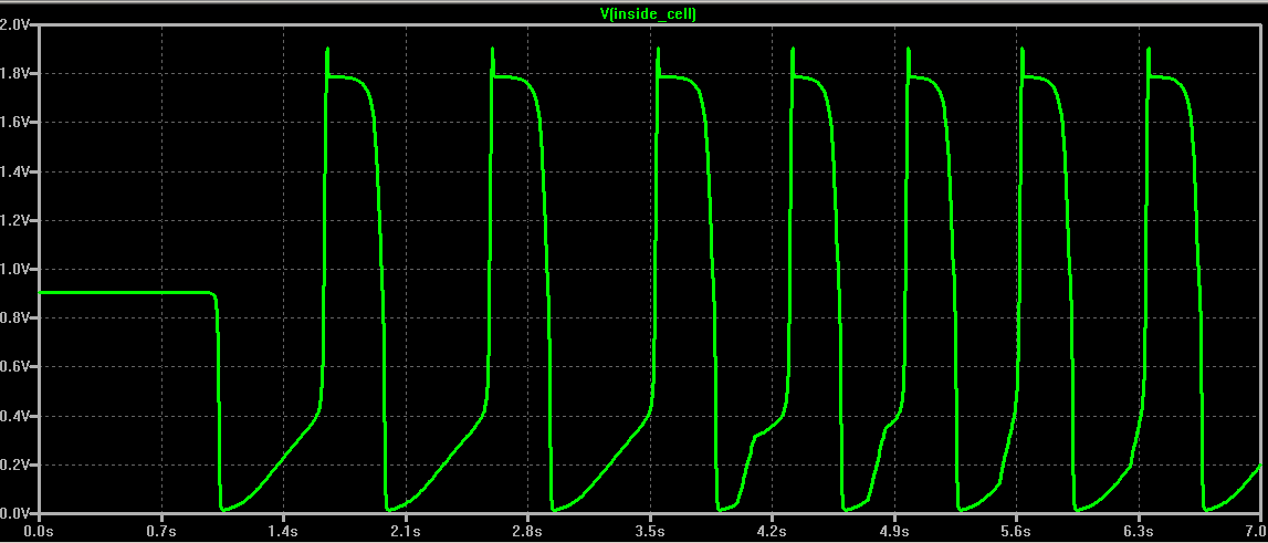
The implementation below includes a pulse generator which turns on at
4.0 seconds to pace the cell at a rate higher than its endogenous rate.
It takes about 3 beats to completely phase-lock. LTspice model.
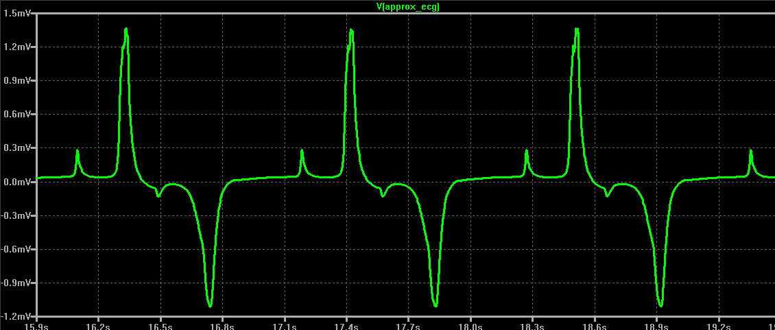
Simulated ECG: Combining several heart cells into a
2D network (ventricle) and driving them from a simulated atrial
pacemaker via a purkinje fiber system, then adding all of the cell
potentials and passing them through a lumped model of the body results
in a simulated ECG. LTspice model zip file.

Modules:
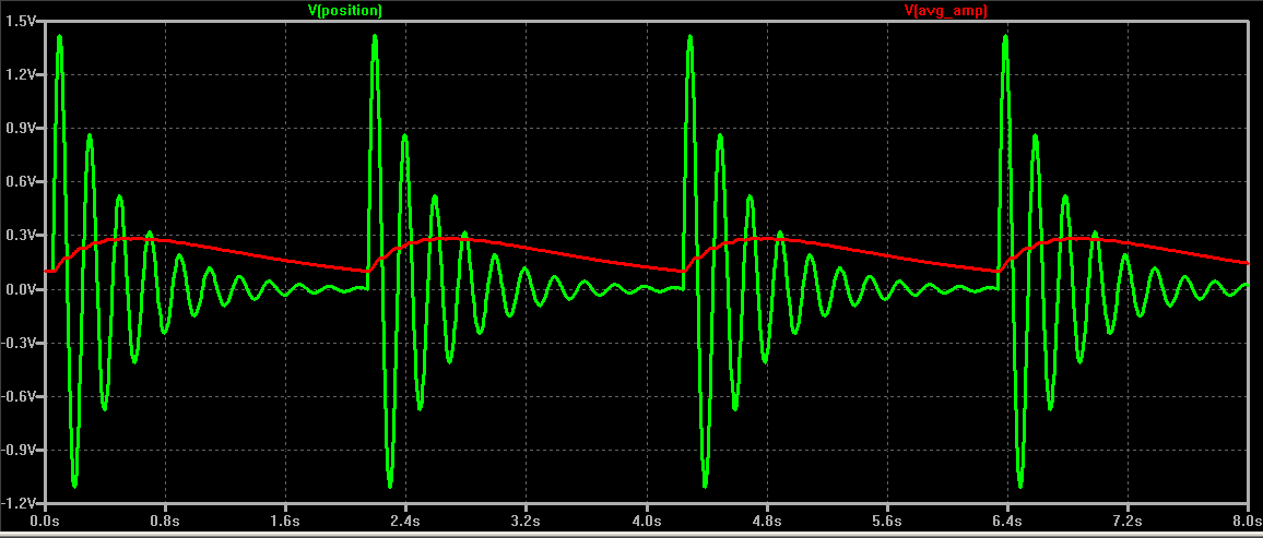
Computational: The modules in this ZIP file
make up a minimal set to converrt LTspice into an analog computer.
Unzip them into one directory. The modules define an adder, multiplier,
constant, absolute value, and integrator. The damped_osc_test.asc
file (in the zip file) can be used to test the modules. Plot the
position output versus time, as below. The reset input on the
integrators restarts the integrals at the initial conditions, therefore
restarting the simulation. The damped spring-mass oscillator equation oscillates if the damping is low enough. To set the value of the constant module to 10 (for example), right-click and enter constant=10. The average amplitude calculation uses a lowpass filter to detect when to restart the integrators.
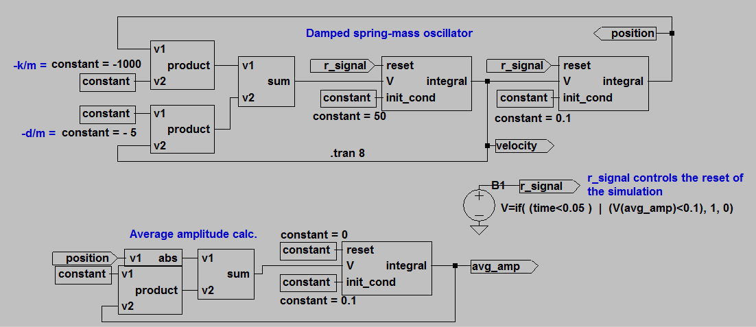
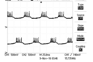
Noise: The noise module I wrote produces
band-limited, white noise with settable band width and amplitude, and
average value of zero. Below is the module circuit and an example of its
use. To use this download and put in the same directory the following
files: noise_module.asc, noise_module.asy, and noise_use.asc. Open noise_use.asc and run it, click on the noise signal to view it. In the Simulate>Edit Sim Command
dialog...
Fascinating. Actually understanding signals (biological and physical) better was one of the major reasons I got into electronics. The idea was to get used to all the complex math (or better yet helpful tools) so I could do something with the observations, but also learn how to sample signals that are weak or sampled under difficult conditions.
This is exactly what I was looking for. Thanks!