 Voja Antonic
As the video signal and the corresponding sync signals are generated by software, the console contains a minimum of hardware. There is also an audio signal output with five binary tone channels, mixed by a passive resistor network. Two of those channels are used for sound effects, similar to ones used in video games of that time (early eighties) and three for background music. This output is capable of driving line output for PC speakers or headphones.
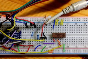
It should be noted that there is no video processing unit, PGA or any special purpose chips, and that PIC microcontrollers are not designed for video signal generation. Everything is achieved by a series of different design tricks and some compromises. As te game does not run on PC but on stand-alone unit, screenshots are taken by camera from VGA monitor or directly from Photoshop, which was used in bitmaps creation process.
Video and audio generators, which are the vital parts of the firmware, are the parts of the operating system, which will soon be documented, and can be used for any other game or application. As the timings are critical, those parts are written in assembly language, but all the other parts of the program (scenario for some other games or any other application) may also be written in some other programming language, preferably Microchip's C. In this case all parts are written in Assembler, but only as a result of author's preference.
At the moment, only the game Jumping Jack is written for the platform, well known to those who played with the Spectrum personal computer back in the day. However, once a new game is created, it is easy to download it from the computer, via the serial port (which is not visible at the photo). The console has USB connector, but it is used only for 5V power supply. Unfortunately, microcontrollers which are packed in DIP packages (with thru-hole soldering, convenient for DIY projects and workshops) do not have USB interface but only serial ports, so you have to use RS 232 if you want to download some new game.
HARDWARE
This project is based on PIC24EP512GP202 microcontroller, which is 16-bit Microchip's MCU with 512K of internal flash program memory, 48K of internal data memory, packed in standard 28-pin Shrink-DIP case. This is the schematcs diagram:
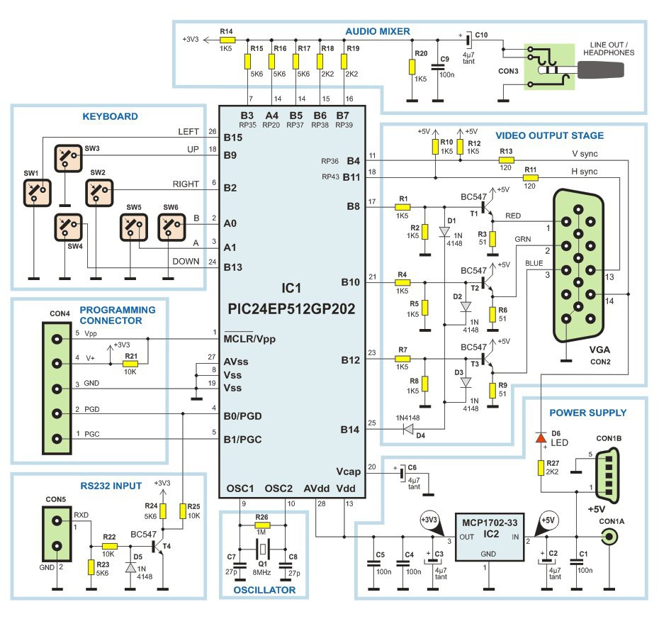
The whole unit uses +5V power supply (2.1 mm coaxial CON1A or mini USB CON1B connector, but take care not to use both!). Measured current consumption is 77 mA. LDO regulator MCP1702-33 is used for +3.3V supply for MCU.
Instead of quarz, you can use ceramic resonator for the oscillator, but some of resonators will produce significant frequency jitter, which is visible as horizontal pixel instability on the screen. It is also possible to use internal FRC oscillator with PLL, but, of course, the jitter will be even worse.
R, G and B video hardware drivers are realized by simple passive attenuators (R1R2, R4R5 and R7R8) and NPN transistors (as emitter followers) T1-T3. There are no special requirements for those transistors, but the low current types (=< 100 mA) are reccomended, as the high current ones typically have lower bandwidth. Intensity control (for "dark" colours and gray) uses standard silicon diodes D1-D4. Do not use Schottky diodes, as their forward voltage drop is too low for proper dark colour representation in analog video signal.
5-channel audio mixer uses simple passive resistor network. Capacitor C9 is used for passive, first order low-pass RC filter. Pull-up resistor R14 is used in two-step volume level control circuit. As all outputs are pure binary (on-off), low volume level is managed by software, when the output port pins are held in open-drain state (selectable in ODCA and ODCB registers), as in that case resistors R14-R20 create additional voltage attenuator, for each output individually.
VGA SIGNAL
Video processors are not typically embedded in microcontrollers, so using the external video display unit is considered in gaming consoles. As this is the minimalistic project, VGA...
Read more »


 Alexander Izmailov
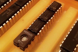
 SHAOS
SHAOS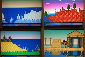
 Nicola Wrachien
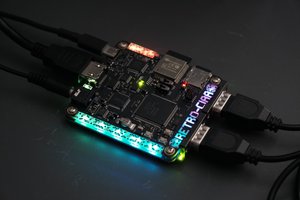
 Santiago Germino
Wonderful !!!