 Thomas Bladykas
Rationale:
A little bit of background: I am a high school student currently in my 3rd year of engineering classes. Ever since my freshman year, there has been this old Makerbot Replicator (5th Gen) sitting on top of one of the counters in the back room. Apparently, it caused so much trouble that when the school purchased an Ultimaker 2+ to replace it, they never so much as glanced at it again.
So, what's wrong with it? Let's go over why these printers are characteristically... crap.
- They do not have heated beds. At all. For a machine still sold today. Painter's tape anyone?
- The hotend is literally loose to use as a bed leveling probe.
- Smart Extruder. Enough said.
- The electronics are completely closed source. And rather than using stepper drivers, it uses H-Bridge motor drivers. Aka, what's a step?
- You're stuck using the Makerbot slicer.
- Makerbot support will shaft you. And the warranty will expire in 3 months, leaving you with a boat anchor.
- There is planned obsolescence written allllll over this.
Goals:
Effectively, retrofit RepRap electronics and parts into the printer for under the price of a new PSU and Smart Extruder (around $300). But more specifically:
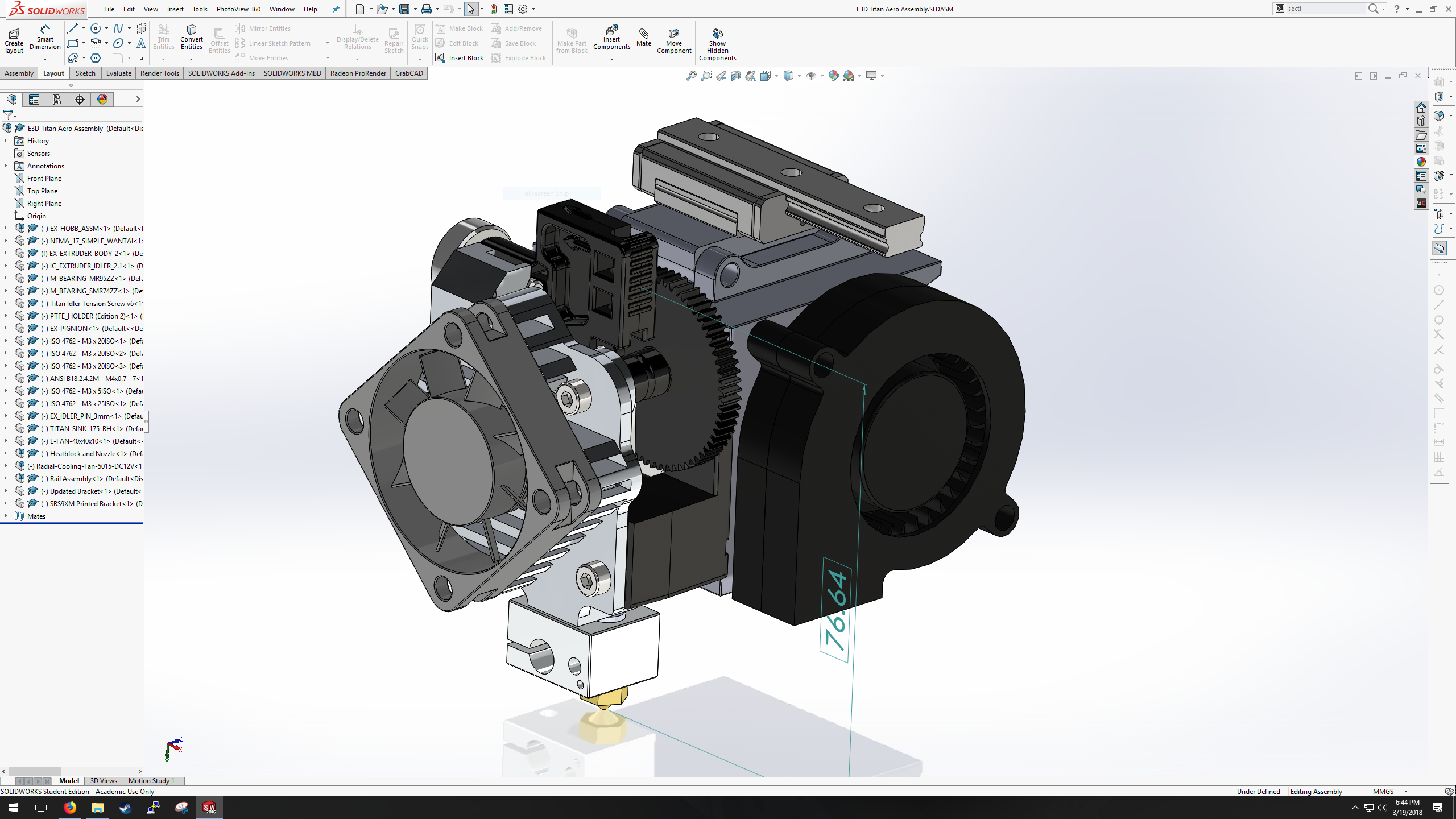
- Upgrade to an E3D Titan Aero hotend/extruder assembly.
- Add a heated bed.
- Increase build volume & upgrade z-axis assembly.
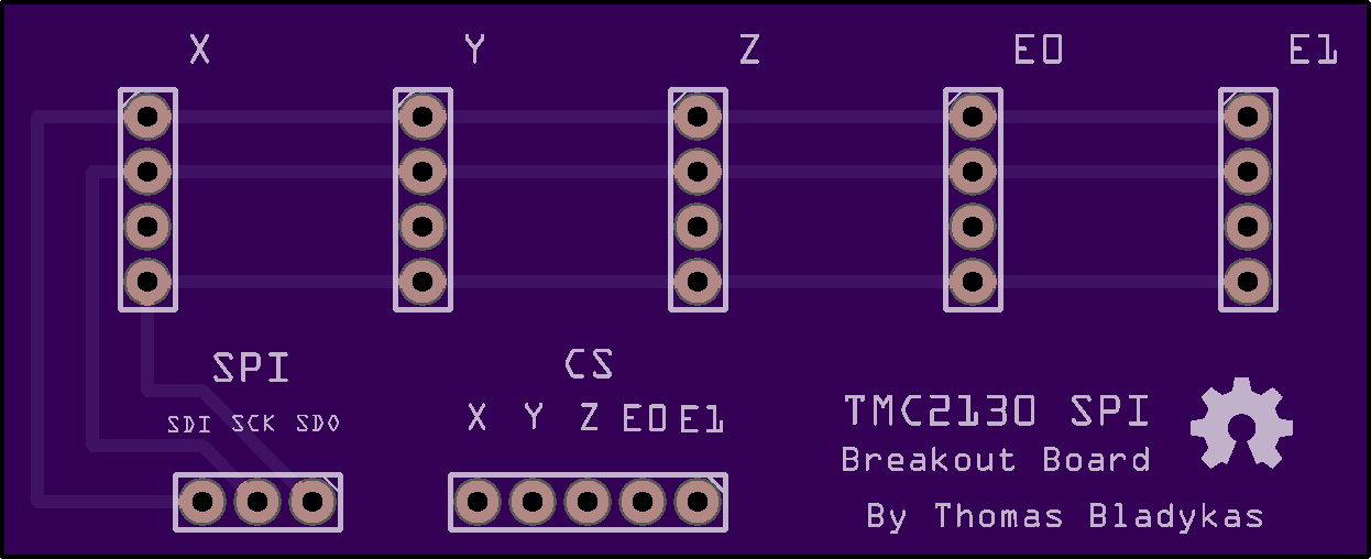
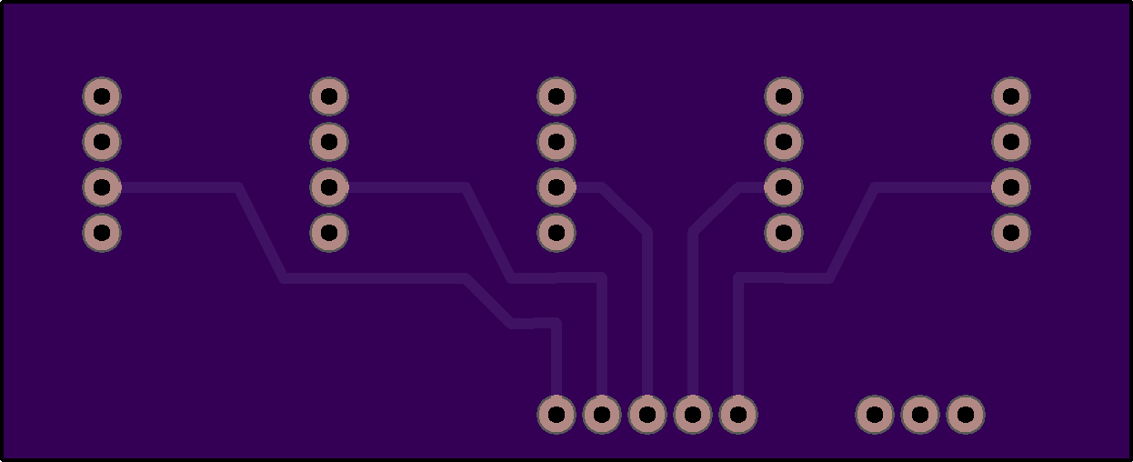
- Swap out ALL electronics for open source, or at least retrofit existing parts.
- Reverse engineer the MakerBot electronics.


 cprossu
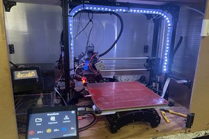
 Sam Griffen
 Myles Eftos
How is it going? I'm unable to see several of the pictures. Are the links expired?