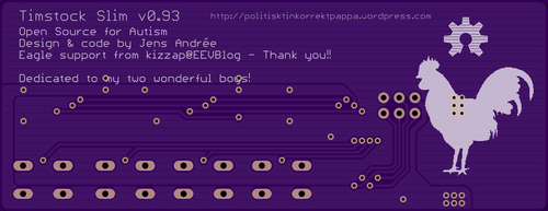
 jens.andree
Having two sons who are autistic I've seen, and used, most available tools developed specifically for kids with their disabilities. Some are great, some are not, but they all have something in common: they are all horribly expensive!
I don't mind people making money - not at all - but overcharging just because you can is not something I can stand behind so several years ago I started to make my own tools and aids for the boys, and at the same time I was able to customise them to suit their specific needs.
My first version of my cheap Timstock was a free Android app that recycled a used/discarded phone into a free tool - instead of paying $200+ for a small box with four buttons and a handful of LEDs. This was well received and all the great feedback made all the hundreds of hours spent on precise design, usability and most importantly testing.
Now I'm making the next generation Timstock that will be as cheap as possible.
One issue with the original Timstock is that it's both bulky - and certainly look like a handicap aid... This is not always a good thing since autism is very much a hidden handicap and when the kids grow a bit older most of them try to hide their disabilities. This was why my Android app was so popular because nobody knew what they were using their phones for.
A bit more than a year ago I was asked if I knew about any old phones that was flat enough to be glued into a binder in order to simplify the usage for a young child who needed a Timstock in school for all activities - and the child kept misplacing the ordinary Timstock all the time. At this time I wondered if I could make a slimmer version, or perhaps a 2.0, and see how much I could push the costs?
After some tinkering at home I made a crude prototype and I decided to roll with it! My goal has always been to make it available for max $15 for the end user, thus making it available to everyone regardless of financial situation - quite the opposite to the many available tools on the market that normally runs from a few hundred dollars to way above $1000...
After writing about this on my blog I was contacted by one of the three original inventors in Sweden. He liked what I was doing and after asking him if there were any copyright issues he told me there were none, and that he really liked the idea of making it available to everyone - at low cost. It was also always my intention to make it Open Source - both hardware and software - because then people can customise it if needed or just make own pcb's. The only thing I don't allow is selling it for a profit - and I will chase anyone who tries to make money off it!
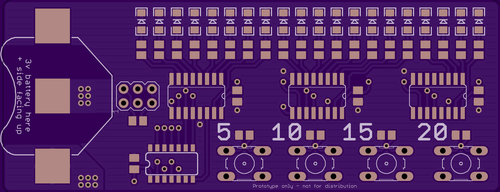
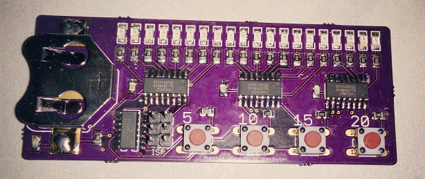
After a hiatus due to me being in an accident and I needed surgery I recently redesigned the whole board and changed many components and this is where I am today - just about to populate the 3:rd generation prototype.
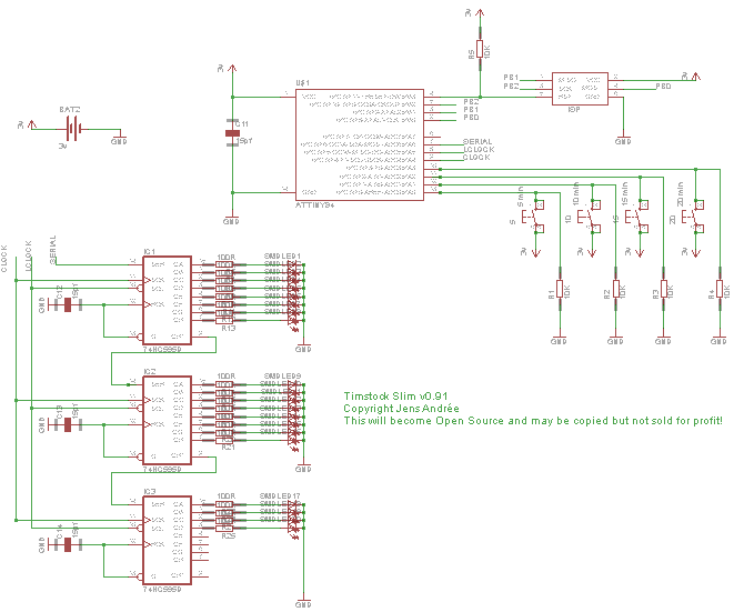
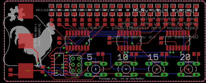
The first prototype used WS2812b LEDs because you could use it to give excellent visual feedback with all the colours, but after testing I just could not motivate the current consumption so I reverted to single-colour LEDs instead and added shift registers to control them. It is based on an attiny84 and has an exposed ICSP header on the pcb for upgrades or customisation.
I hope the 3:rd generation prototype will perform well enough to make a final design of the layout, but this we'll soon find out!
My boys no longer need a Timstock to cope with the tasks in school e.g. but there are so many that do need one out there and they simply can't afford one so I have to finish what I've started.
To be continued...
For those of you who don't know what a Timstock is and how to use it? Here is a quick description.
The Timstock tool is a device for visually, and auditory, show the user progression of time, in 4 different increments/fixed times.
The most common configuration is 5, 10, 15, and 20 minutes, and each button has its own colour. When you press one of the buttons the time starts to count down until 0, when a visual and optional auditory alarm is displayed....
Read more »


 RRichmond
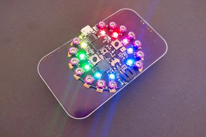
 deʃhipu
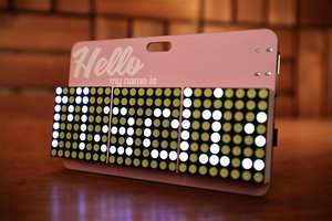
 Madison
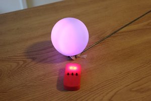
 Bob Baddeley
Hey, how is this going? Really interested to see end product.