 RasmusB
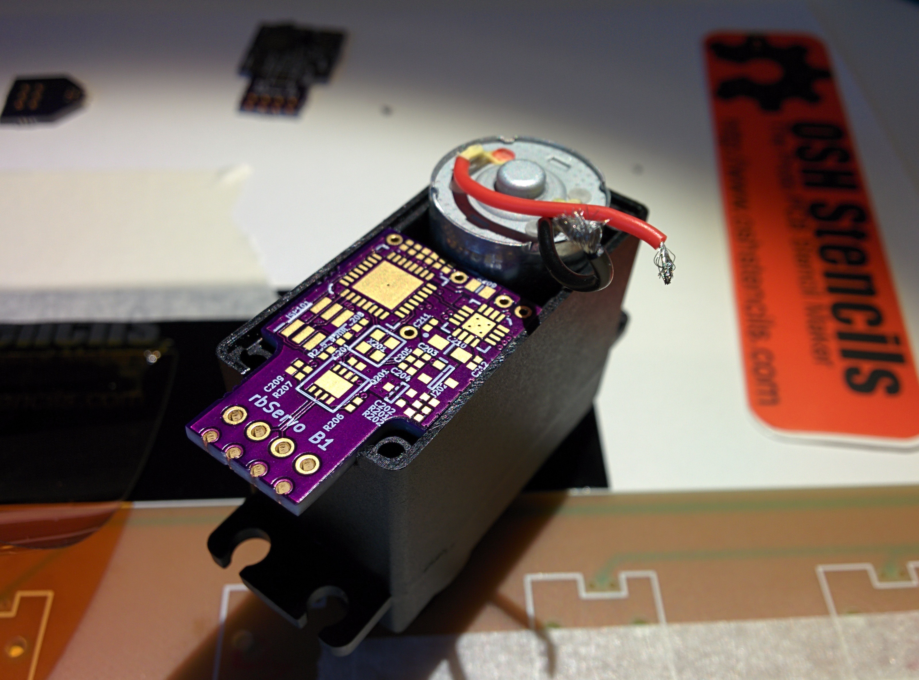
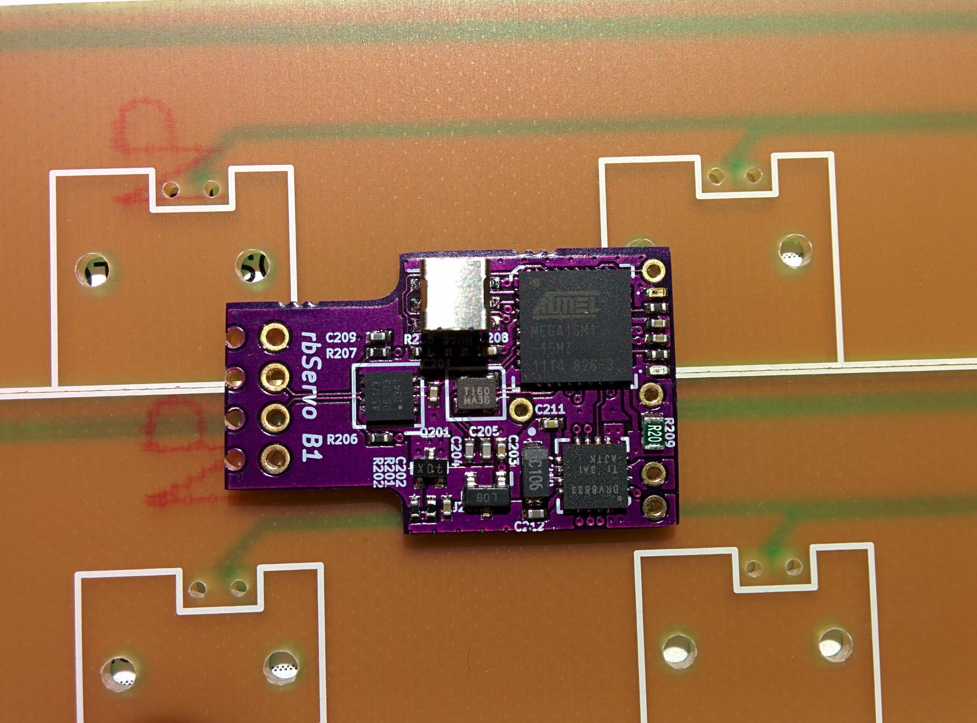
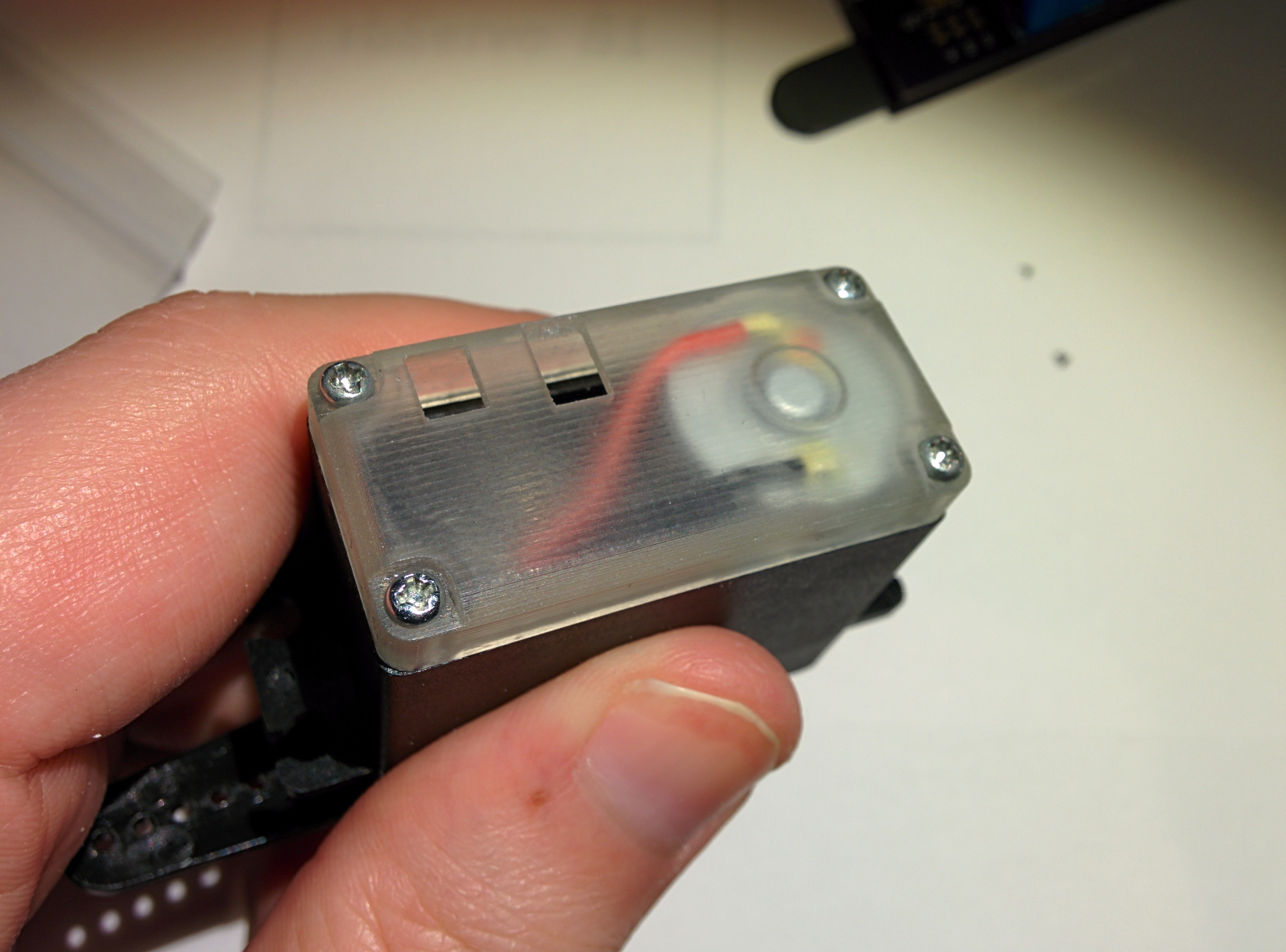
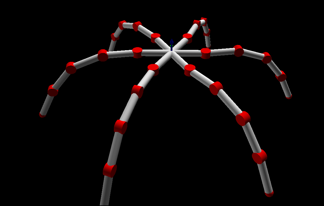
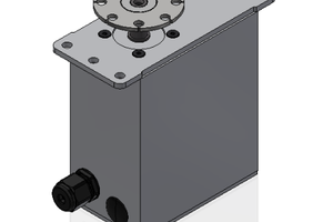
This is a modification of a standard RC servo. My development is done on the cheap, metal geared TowerPro MG995. The controller board is replaced with a more advanced controller with support for CAN. This enables position feedback, motion profiles, current and voltage monitoring, custom PID parameters and so on.
0%
0%
Become a Hackaday.io member
Already have an account? Log in.
Just one more thing
To make the experience fit your profile, pick a username and tell us what interests you.
Pick an awesome username
hackaday.io/
Your profile's URL: hackaday.io/username. Max 25 alphanumeric characters.
Pick a few interests
Projects that share your interests
People that share your interests
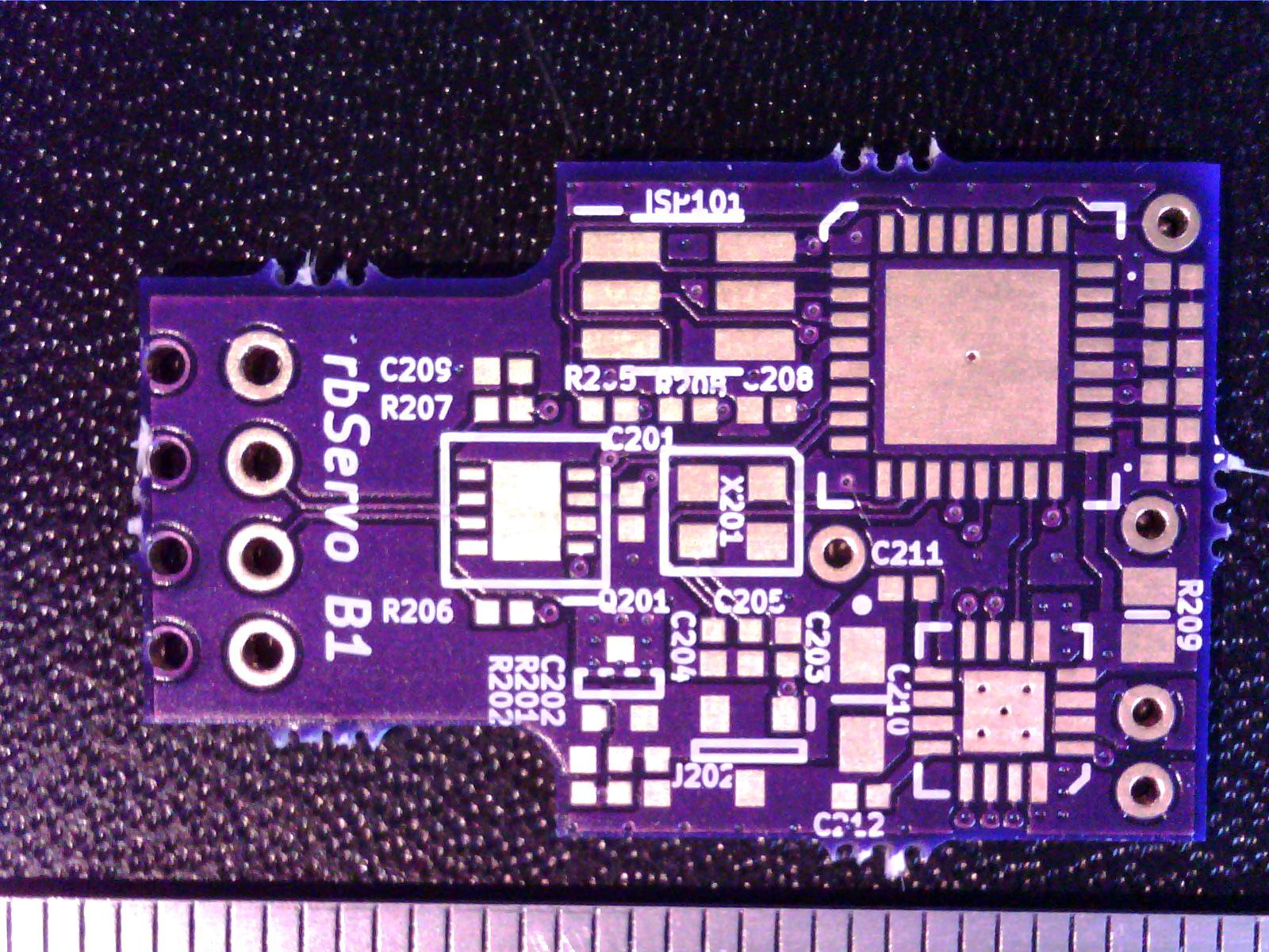
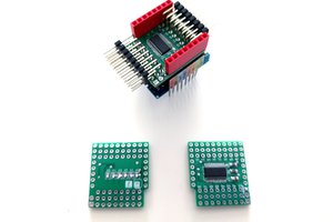
 Other than the outline alignment issue, the board is stunningly beautiful! The purple solder mask on this board is less glossy compared to the 2-layer boards I have bought previously, and it looks a bit more refined. The soldermask alignment is perfect, and the silkscreen is easily on par with boards that cost ten times as much! The drill alignment is also very good.
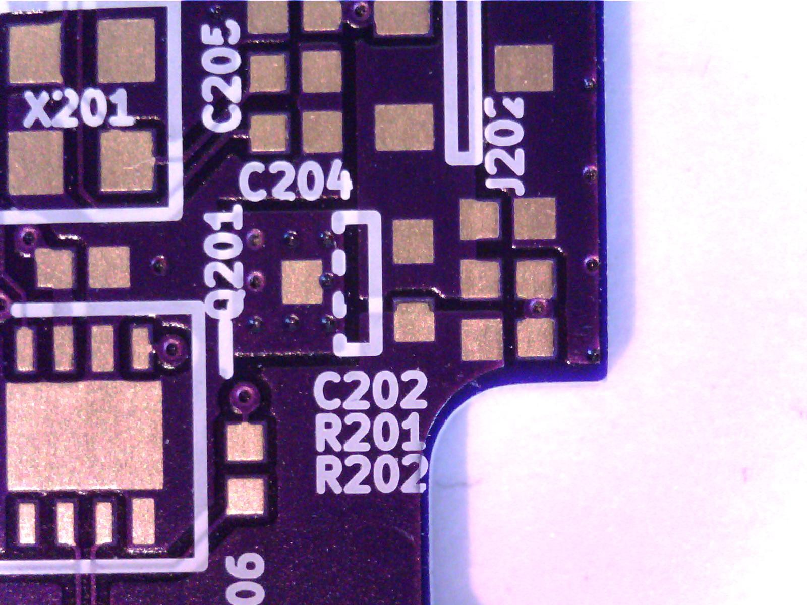
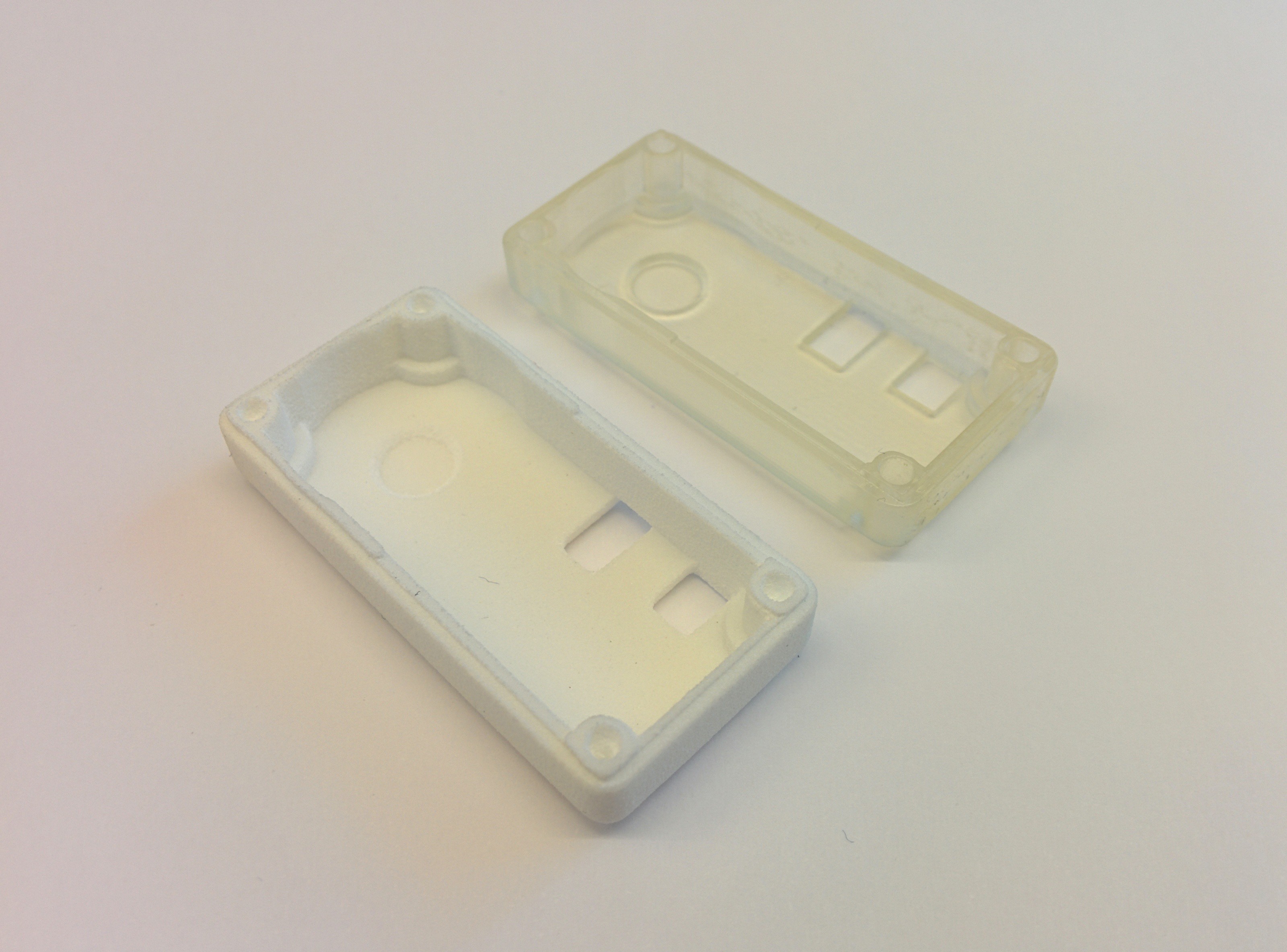
 I got all the components I need last week, so now I'm just waiting for my PCB:s and my solder paste stencil. The cutout in the lid is for the debugger adapter, let's hope everything lines up.
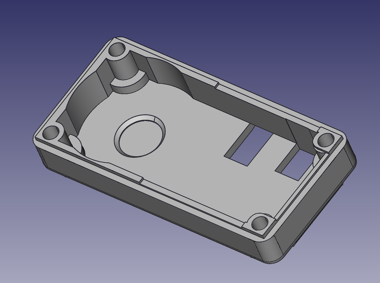
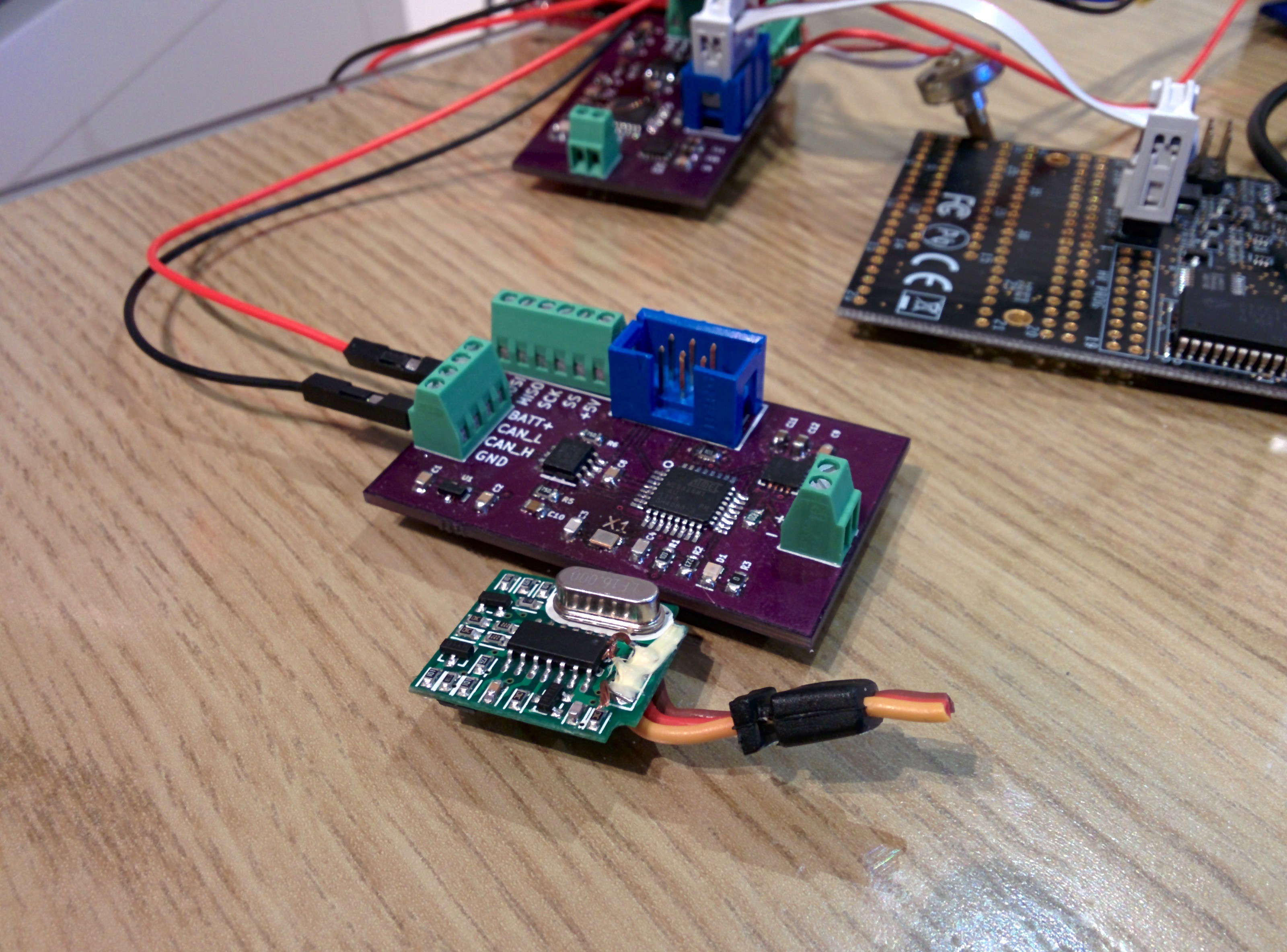 This prototype was build to to a basic concept test - especially of the CAN communication. After being completely fed up with trying to build some kind of USB - Arduino - MCP2515 - CAN adapter, I built

 deʃhipu
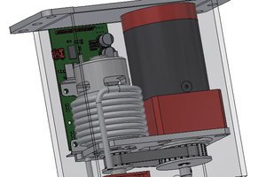
 patchartrand
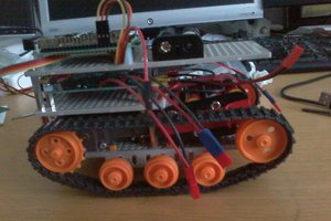
Will try the export-and-carefully-go-ahead method :)