 Jean-François Duval
In this Project Log I’ll show you how I’m using DMA on a PSoC. My example will be based on the ADC, but it’s basically the same thing for all the peripherals. What’s DMA? From Wikipedia: “Direct memory access (DMA) is a feature of computer systems that allows certain hardware subsystems to access main system (RAM) memory independently of the central processing unit (CPU).”
The same page explains why this is useful: “Without DMA, when the CPU is using programmed input/output, it is typically fully occupied for the entire duration of the read or write operation, and is thus unavailable to perform other work. With DMA, the CPU first initiates the transfer, then it does other operations while the transfer is in progress, and it finally receives an interrupt from the DMA controller when the operation is done. This feature is useful at any time that the CPU cannot keep up with the rate of data transfer, or when the CPU needs to perform useful work while waiting for a relatively slow I/O data transfer.”
In Current controller: hardware I explained that I want my current sensor readings (done with the ADC) to be synchronized with the PWM. I wrote “Every 5th ADC sample a DMA interrupt is triggered”. Without DMA I would have had an interrupt every cycle (100kHz => 10µs). Let’s say that I need 25 instructions to enter the interrupt service routine (ISR), get the ADC reading, store it in an array, and return to the main program. One instruction on the 80MHz CPU takes 12.5ns; reading one value will take 312.5ns. 312.5ns every 10µs is 3.25% of my computing budget, and all I did was grab one reading!
To minimize the influence of noise I want to average multiple samples. In this case, a moving average of 5 samples will give me a refresh rate of 20kHz, perfect for this application. With the DMA controller taking care of getting the samples and placing them in an array I only need one ISR, thus requiring only 0.65% of my computing budget for this task.
To get started I followed one video and one application note: PSoC Creator Tutorial: Working with DMA & AN52705 Getting Started with DMA.
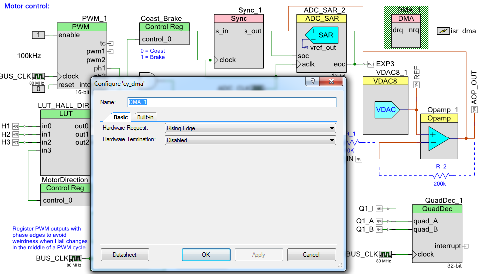
I dragged a DMA component (DMA_1) and I linked it to the End of Conversion (eoc) output of my ADC. I selected Hardware Request = Rising Edge. The isr_dma component is used to call an interrupt when a DMA transfer is complete (in that case, after 5 samples have been acquired).
Use Tool => DMA Wizard to generate code. You can adjust your settings via the GUI, or you can keep the defaults and edit the code manually. Copy and paste the code in your project (I placed it in analog.c, the file that holds all the ADC conversion software). Here’s what I have:
//DMA for ADC SAR 2 transfers
//Triggers an ISR after 5 transfers
void adc_dma_config(void)
{
	/* Variable declarations for DMA_1 */
	/* Move these variable declarations to the top of the function */
	uint8 DMA_1_Chan;
	uint8 DMA_1_TD[1];

	/* DMA Configuration for DMA_1 */
	#define DMA_1_BYTES_PER_BURST 2
	#define DMA_1_REQUEST_PER_BURST 1
	#define DMA_1_SRC_BASE (CYDEV_PERIPH_BASE)
	#define DMA_1_DST_BASE (CYDEV_SRAM_BASE)
	DMA_1_Chan = DMA_1_DmaInitialize(DMA_1_BYTES_PER_BURST, DMA_1_REQUEST_PER_BURST,
	    HI16(DMA_1_SRC_BASE), HI16(DMA_1_DST_BASE));
	DMA_1_TD[0] = CyDmaTdAllocate();
	CyDmaTdSetConfiguration(DMA_1_TD[0], 10, DMA_1_TD[0], DMA_1__TD_TERMOUT_EN | TD_INC_DST_ADR);
	CyDmaTdSetAddress(DMA_1_TD[0], LO16((uint32)ADC_SAR_2_SAR_WRK0_PTR), LO16((uint32)adc_dma_array));
	CyDmaChSetInitialTd(DMA_1_Chan, DMA_1_TD[0]);
	CyDmaChEnable(DMA_1_Chan, 1);
}
adc_dma_config is called once, when I initialize all the peripherals. I’m using 2 bytes per burst because the 12bits ADC result is stored in 2 bytes. DMA_1_REQUEST_PER_BURST is 1: I want one transfer every time the drq line sees a rising edge. adc_dma_array is a buffer defined in the same file (int16 adc_dma_array[ADC1_BUF_LEN];); this is where your ADC values will be stored. Everything else is left at the default settings.
Adding the isr_dma component generated a file named isr_dma.c. The function called when a DMA transfer is complete is CY_ISR(isr_dma_Interrupt):
CY_ISR(isr_dma_Interrupt)
{
    /*  Place your Interrupt code here. */
    /* `#START isr_dma_Interrupt` */

	volatile int32 adc_sum = 0;
	volatile int32 adc_avg = 0;

	//Read last ADC value
	adc_sum = (int32)(adc_dma_array[0] + adc_dma_array[1] + adc_dma_array[2] + \
				adc_dma_array[3] + adc_dma_array[4]);
	adc_avg = (adc_sum / 5);

	ctrl.current.actual_val = (int32)(adc_avg - CURRENT_ZERO);
	//Used by the current controller, 0 centered.

	if((ctrl.active_ctrl == CTRL_CURRENT) || (ctrl.active_ctrl == CTRL_IMPEDANCE))
	{
		//Current controller
		motor_current_pid_2(ctrl.current.setpoint_val, ctrl.current.actual_val);
	}

    /* `#END` */
}
The comments should make it clear that all it does is average 5 values and call the motor current PID loop. (Calling a function in an interrupt is never recommended, but in that case I optimized motor_current_pid_2() to be as short as possible and I confirmed on the oscilloscope and signal analyser that everything was fine.)
Finally, here’s a scope capture. 1 is the 100kHz PWM (~30% duty cycle), 2 and 9 show the sampling of the ADC (it’s sampling when 9 is high), starting in the middle of the PWM and 8 is the DMA ISR. As you can see, the code is called once every 5 cycles.

Discussions
Become a Hackaday.io Member
Create an account to leave a comment. Already have an account? Log In.
Interesting that you chose to make the control loop update synchronous to the DMA interrupt. You clearly are an expert here, though. Does this mean that the control setpoint will updated for the whole motor driver as each individual phase is updated? So effectively thrice per sensing of the overall motor current state?
Might it be better to sense all three phases, then update? Although then you have variable lags on the 0-th order hold on the sampled current value of the other two phases.
I mean, clearly what you have works, from your videos.
Are you sure? yes | no
Hi Andrew! Let's say that my motor has 4 poles (4*3 phases = 12 phase commutations per rotation) and is spinning at 1000rpm. That's 16.7 rotations per second (rps), or 60ms per rotation. Each Hall code will be activated for 60ms/12 = 5ms. My PWM is 100kHz (10µs), so I'll have 500 PWM cycles per Hall code. I'm dividing the frequency by 5, that's still 100 current controller updates per Hall code, a much faster refresh rate than what I'd get from synchronizing the current loop with the 3 phases.
Does that explication make sense to you? Do not hesitate to ask more details!
Are you sure? yes | no