Specs:
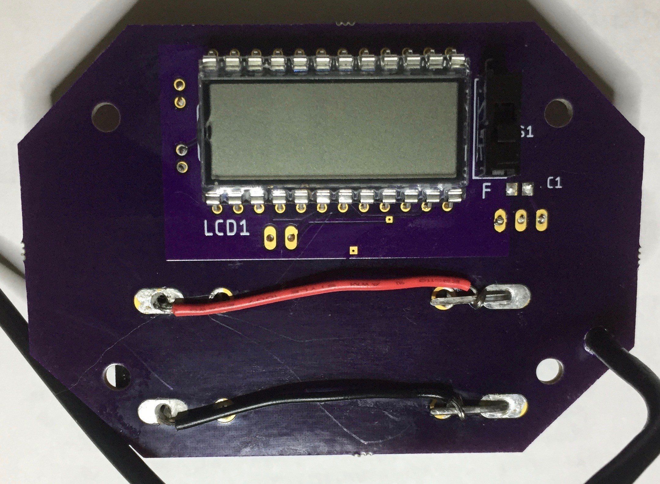
- Display: 2 1/2 digit LCD
- Units: user selectable Celsius or Fahrenheit
- Range: -40C (-40F) - +50C (122F)
- Accuracy: +/- 2C
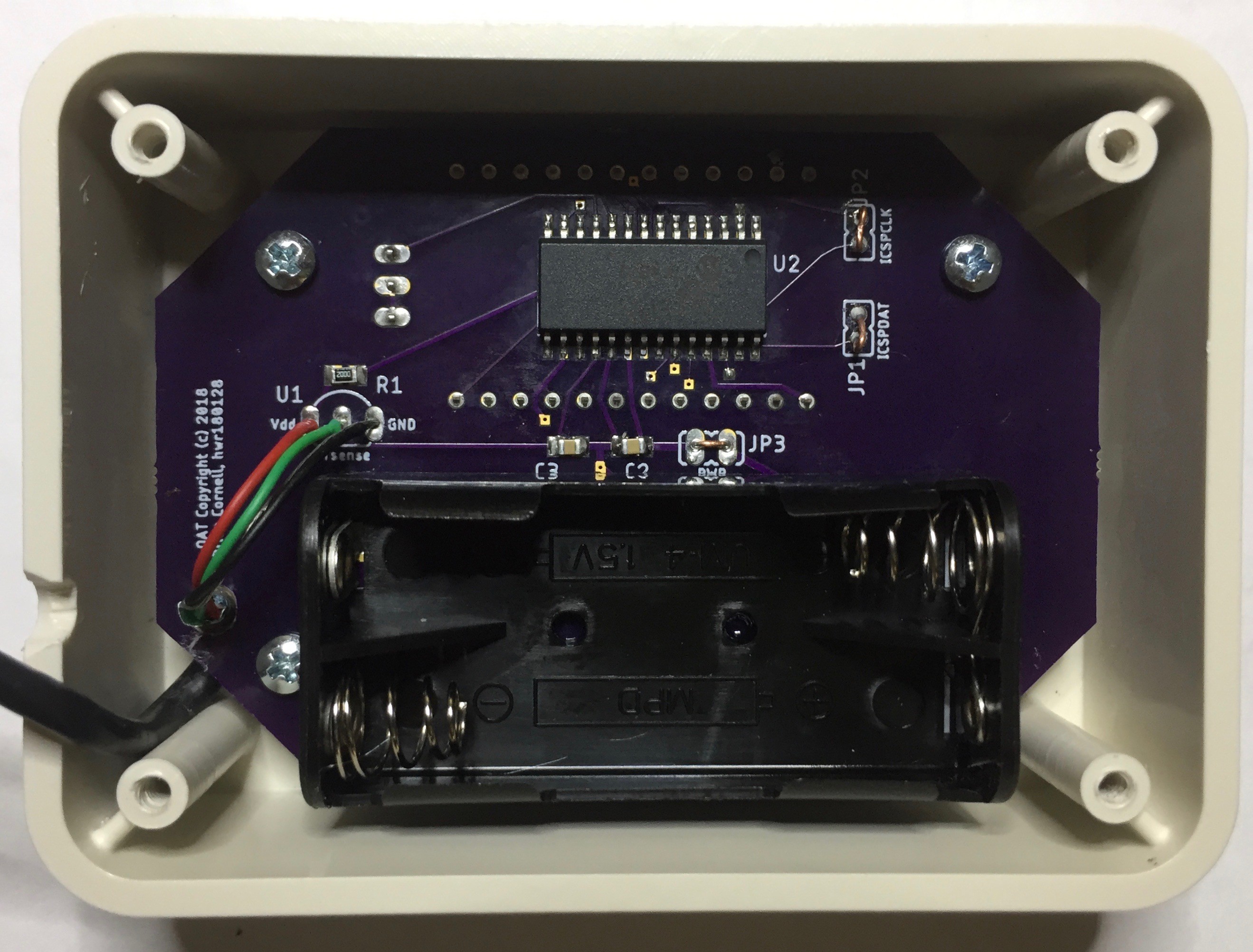
- Batteries: 2 x AAA
- Expected battery life +1.5 years
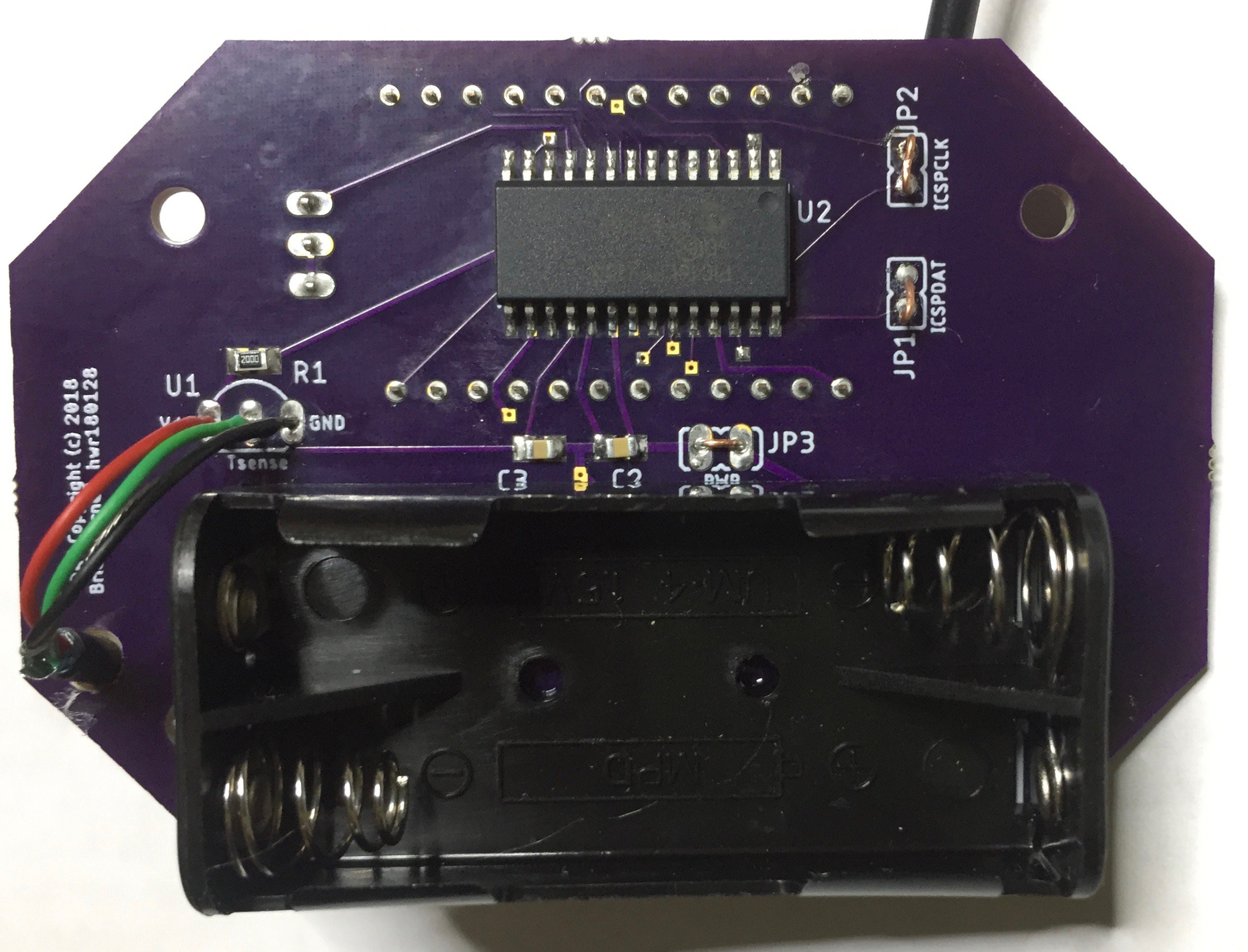
The design is very straightforward. The PIC16LF19155 was chosen for reasonable pin count, ease of soldering, and the integrated LCD controller. I would have like to have used a larger LCD but this was the largest available on Digikey. Now that I have it in use I've found it okay.
The temperature sensor is the trusty Microchip MCP9700A in the TO-92 package. It's a great little sensor that draws only a few microamps and uncallibrated is accurate to about +/- 2C across it's measurement range. In fact, I decided to not compensate it since in the 0 - 40C range it is actually more accurate without (and only marginally less so down to -25C)! See Microchip's application note AN1001 if you want to understand the details behind this. Regardless, this makes the math code very simple.
The PIC16LF19155 is a new release from Microchip and features a new 12-bit ADC. For those of you familiar with Microchip's 8-bit line they have featured rudimentary 10-bit SAR ADCs for some time that perform reasonably well for low-accuracy work. The 12-bit is a nod to the importance of high accuracy / speed data acquisition these days. It looks & smells more like a low-end Sigma-Delta (it has a rudimentary DSP but they don't call it that).
But those features aren't used in this design since the data acquisition rates are very low and it's essentially dealing with DC signals and a low noise footprint.
When powered up the PIC configures the LCD & ADC modules along with pins and supporting peripherals. It then enters the run loop: wake-up, power-up the temp sensor, check the switch setting for C/F, do several acquisitions of temp signal, power down temp sense, average, calculate degrees Celsius, convert to Fahrenheit if selected, update display, and go back to sleep. That's it!
The watchdog timer wakes the PIC about every eight seconds; so this is the maximum rate at which the display will update. The LCD drive remains on full-time.
 Raphael
 Ivan
Ivan
 Paulius J.
 Max.K
Max.K