 6502Nerd
Ok, so this part is not so much a blog, but a place to throw up the storyboard of my project through photos I have been taking from the beginning to present.
So I started very basic. I don't have pics of the 6502 in a free run set up, but the following images give a flavour of just how bare-bones it all started..
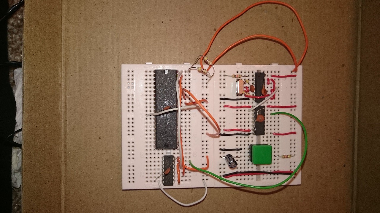
Clock and reset circuit, amongst the first thing I built and can be seen in the current set up. What's that tiny vero board on the right with a screw sticking out of it? Well it is my original power supply - stepping down from 9V to 5V. That screw is a heat sink!
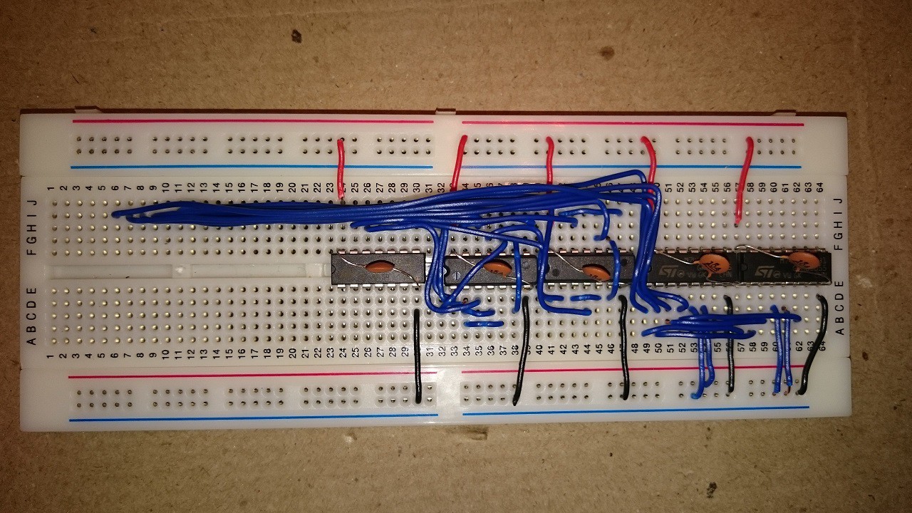
 Initial decoding logic - don't even ask me what I was thinking! This has definitely not made it through to the current set up, in fact I never got to using it as realised it had impractical (or at the least worrying) levels of delay due to the number of cascading chips I was using.
 When I got hold of a TMS9918, I tried to work out if it was alive with a little free-run circuit. All it proves is that the TMS is getting power and a valid 10.738Mhz clock signal, so not really that useful with hindsight..
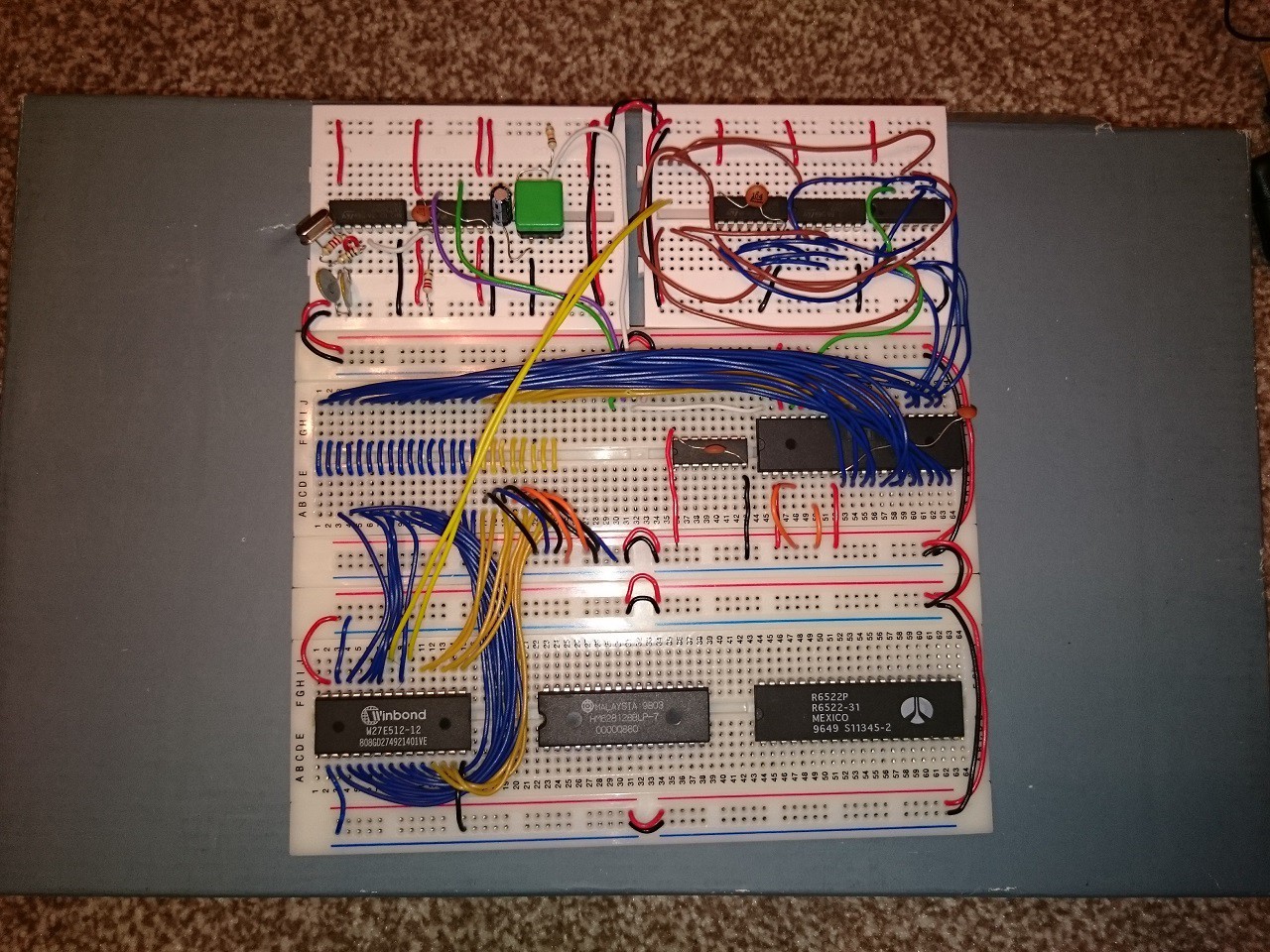
This next pic looks like quite a jump, and in a sense it was - the main layout is taking shape. I decided to try and organise a central address and databus section around which I could wire up the necessary ICs. This board only has some ROM wired up but with an oscilloscope snooping the CPU address bus, I could verify that a programe was running and therefore, it lives! As can be seen, I am using a Winbond 27E512 (later on I stuck with a 27C512, but same wiring).
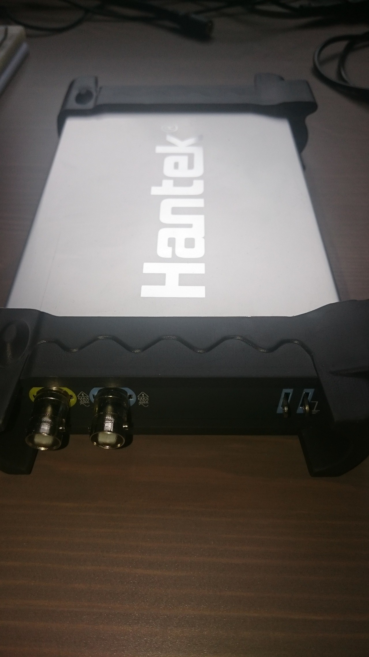
 Talking about oscilloscopes, I thought I shoud put up the core tools I used (and still do). First the oscilloscope. I had a 2Mhz bandwidth handheld puppy, but it was inadequate so invested in a USB connected one with dual channels. Without this I definitely would not have got the board running with all the components I have today.
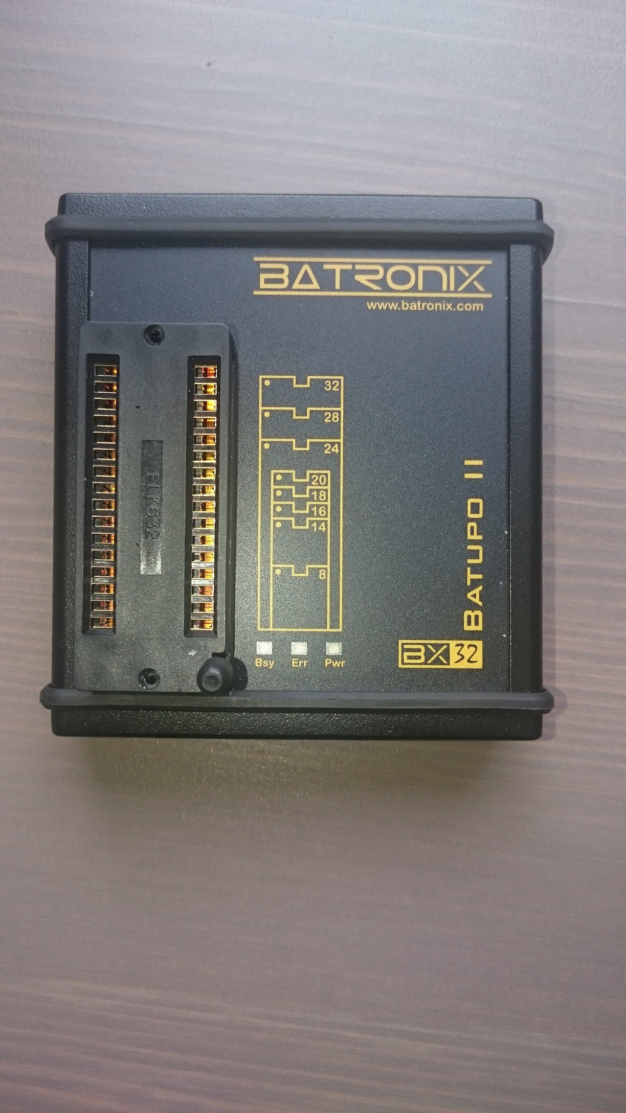
 Next, I have a EEPROM programmer. I did try to go down the authentic route and got myself some EPROMS, programmer and UV eraser! The edit/program/test/erase cycle was depressing so quickly moved on to the BATUPO - I tried some cheap far-East programmers (Top-Win anyone?) but this was and is way more reliable. This is now the most used tool of course as it's all about the software..
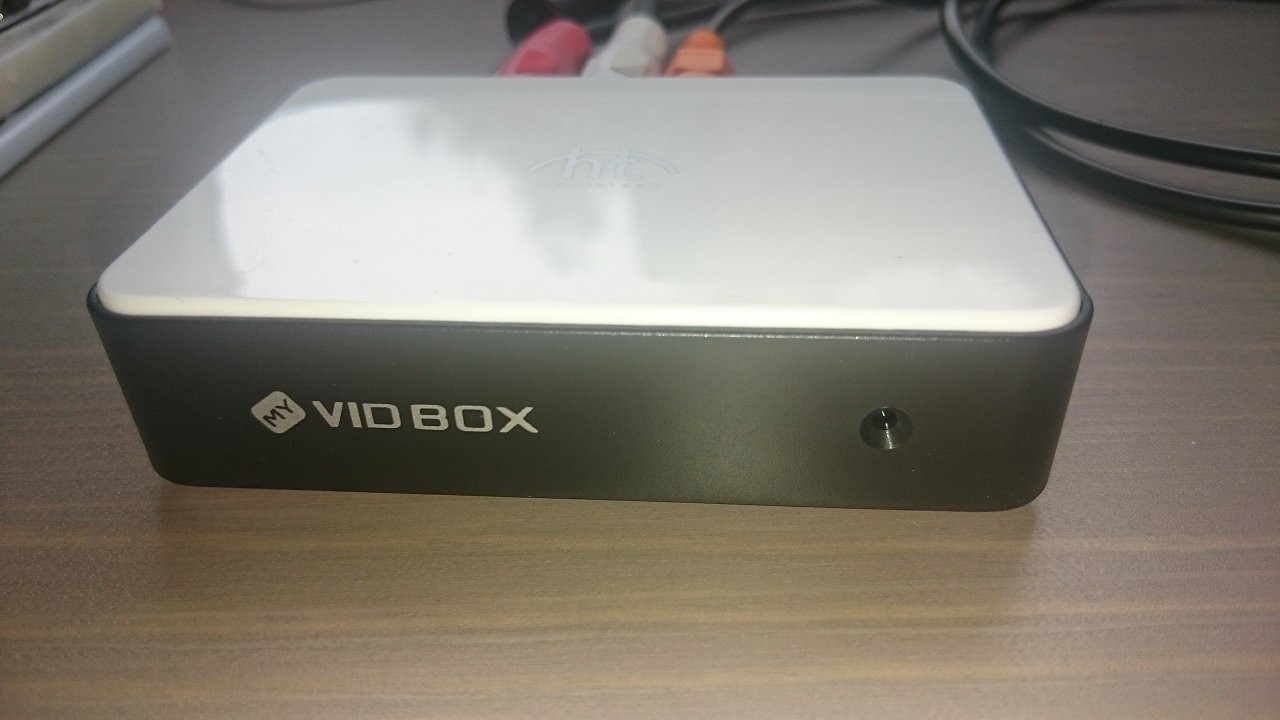
 The other thing I needed was a TV capture device. For a while this worked fine, but the delay on this is horrible, so now am using a regular LCD TV (as I have space in the office because we moved to a larger place in Summer 2015). Still, the TV Out was useful initially when office and desk space was at a premium.
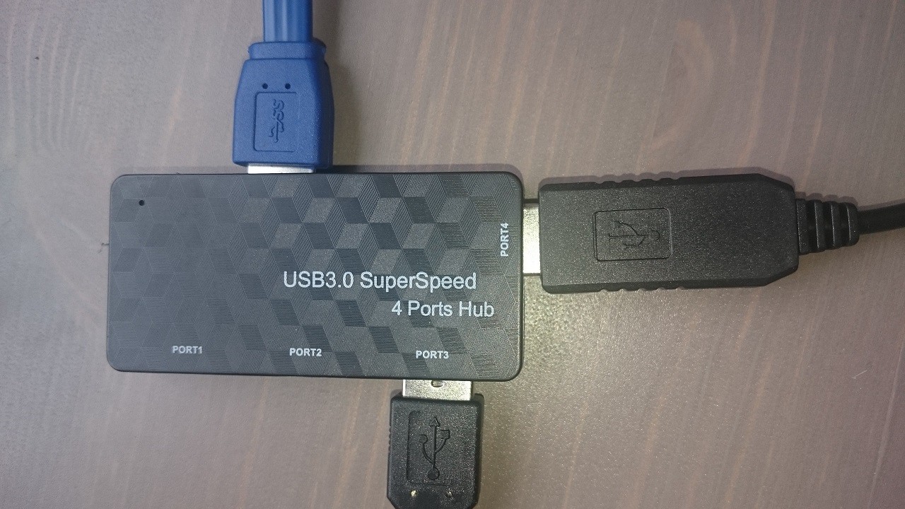
 I ran out of USB ports - Programme, Scope, TV Capture. And that didn't leave room for a serial port! So I needed a USB hub.
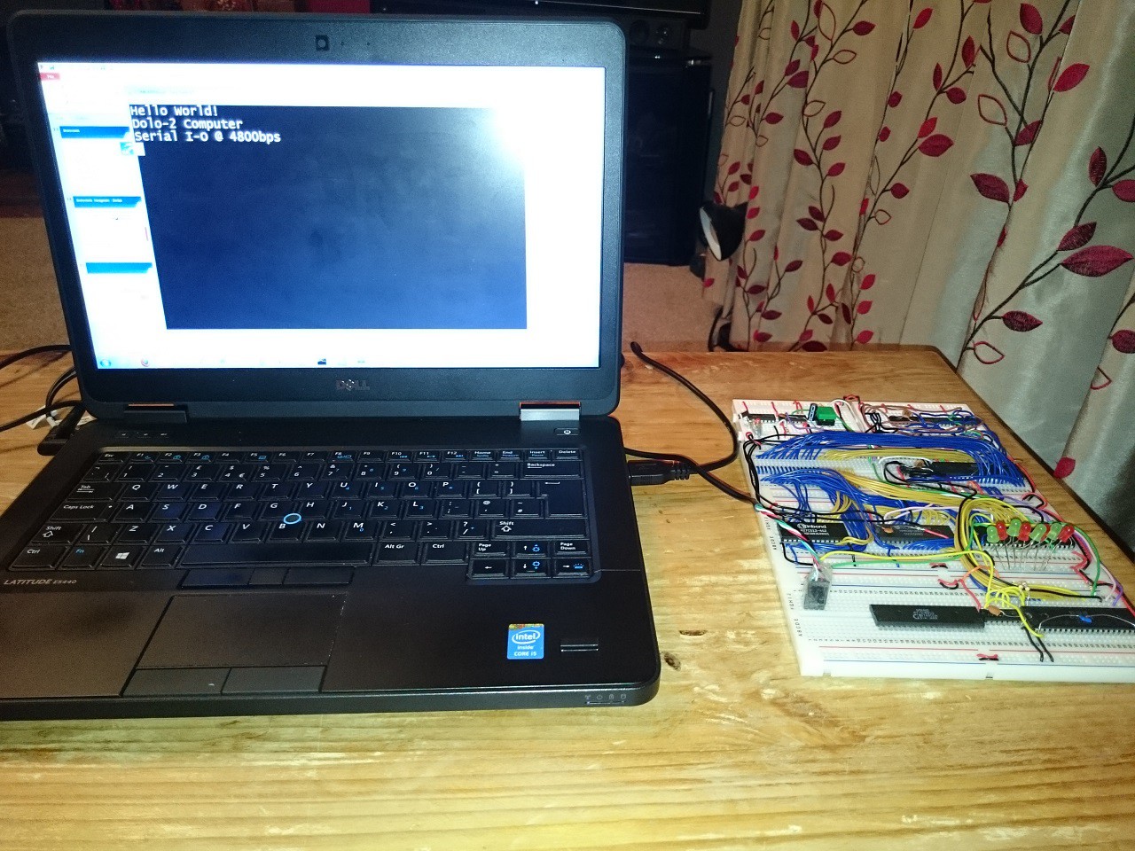
 My initial board was serial only using the 6526 (from a non-function CBM64) to bit-bang the serial line. I managed to get 9600bps reliably, before deciding to do things more properly and implement a 6551 ACIA. The board in this pic has ROM, RAM, 6502, 6526 all working well, with serial I/O the only means of communication. Even so, there is quite a lot of breadboard building up here, and it is starting to get awkward / delicate in moving it.
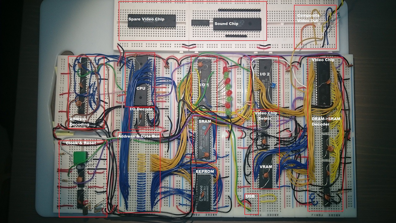
 I sent the following picture to my friend (sadly he passed away too young) when I was explaining the basics of what I had got going. The breadboards are now stuck to a plastic chopping board to keep them together! This is very much the current set up, but with sound added and the IO chips are actually 6522 VIAs rather than 6526 PIAs. The original clock and reset circuit is bottom left.
 More recent pics to follow..
Discussions
Become a Hackaday.io Member
Create an account to leave a comment. Already have an account? Log In.
Fun !
Are you sure? yes | no
Wow!
Are you sure? yes | no