 Nick Johnson
Greenpaks are lightweight, low cost programmable logic devices from Dialog Semiconductor. They're perfect for glue logic and for designing that logic IC you wish existed but doesn't, but they have one major caveat: they're only available in a tiny 0.5mm pitch QFN package.
Fabric8 aims to take the awesome-but-inaccessible greenpak device and make it easily available to hobbyists by providing cheap breakout boards and a development and programming board for them. It's your very own breadboard-based IC fab!


 Clyde D. Corpuz
 Ted Yapo
 agp.cooper
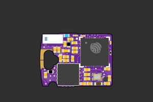
 femtoduino
Inputs for what sort of configuration? How would you interface with them?
I'm not quite sure I see how moving the jumpers to the main part of the board would provide for that possibility; at the very least you'd need a 2-way jumper to disconnect the IO pad as well as connecting GND, and I don't think there's room for that.