 Bruce Land
The Circuit
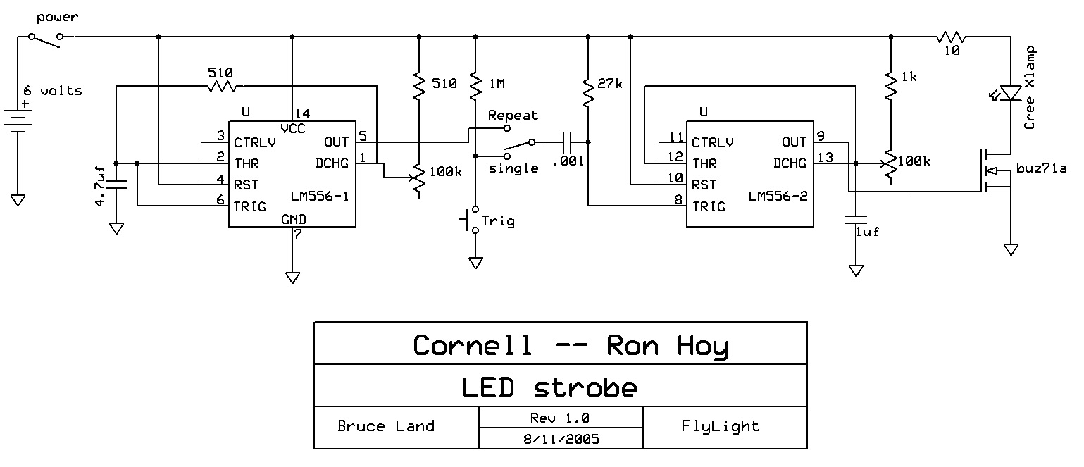
The circuit is a standard pulse generator using two 555 timers (in a single package). Approximate rate adjustment is 1-100 Hz, pulse width is 1 ms-0.5 sec. In single pulse mode, one pulse of the set width is generated when the trigger button is pushed. The button is not debounced, so sometimes you get two pulses. The variable resistor on the left controls rate, the one on the right controls pulse width. The circuit will supply 0.6 amp to the LED, which is above its rating . This means that long duration, high duty-cycle bursts can burn it out. On the other hand, it is very bright.

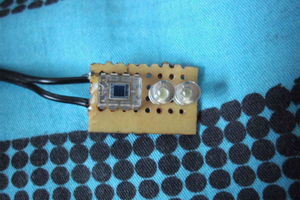
A circuit board was designed using ExpressPCB software. The image of the board is below. The design file requires a free download from ExpressPCB (for windows only). Traces on the top of the board are red, and on the bottom are green. Component values are given on yellow, but are not printed on the board, if you use the cheapest board production service. There are actually two copies of the circuit on one production board (see design file), so you need to cut them apart with a band saw.
Parts list:
- LED is a one watt Cree XLamp™ 7090WBL ordered from All Electronics, part number LED-112 (blue light) or LED-110 (white).
- BUZ71A is an N-channel power MOSFET ordered from All Electronics, part number BUZ71A
- The IC is a NE556 dual timer, digikey part number 296-6504-5-ND, or digikey part number LM556CN-ND
- All surface mount parts are 1206 sized parts from digikey. Capacitors are type X7R from kit part number PCC6-KIT-ND. Resistors are 5% tolerance, thick film, from kit part number CR1A-KIT-ND .
- Variable resistors are Audio Taper Potentiometers jameco part number 255441; manufacturer's part number RV24A-10-15R1-A100K
- Push button and switches can be any small, low power switches. The push button (Trigger) should be normally-open.
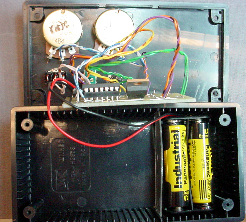
- Battery pack consisted of 4 AA cells (6 volts nominal). The battery holder was similar to digikey part number BH24AAW-ND.
- Box is a 5"x2.5"x2" ABS Speedy box, jameco part number 18913
Construction
Solder the surface mount components first, then a socket for the 556 ic. Put the 4.7 microfarad through-hole capacitor and MOSFET on the board last. Controls were mounted on the front panel, then wired to the board. A small plastic insert held the battery pack at one end of the box. The box is small enough that the printed circuit board was simply pushed against the bottom of the box by the connecting wires. To fit the small box I used, the MOSFET had to be bent flat toward the right side of the board, as you can see in the photo below.
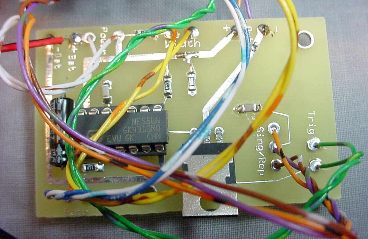
Wires going to the controls were twisted to minimize noise. HOWEVER, it may be necessary to fiddle with the placement of the wires in the bos in order to keep the LED from latching on. When you first turn on the circuit be ready to immediately (< 2 seconds) turn it off if the LED is steadily lit. The LED will burn out quickly if it runs all the time. If the LED is always on, then move the wires around until the LED starts to flash. You must rearrange the wires with the unit turned off. Not shown in these photos is the 10 ohm, 0.25 watt resistor which connects the circuit to the LED. Adding the resistor (on the phone jack) stabilized the circuit.
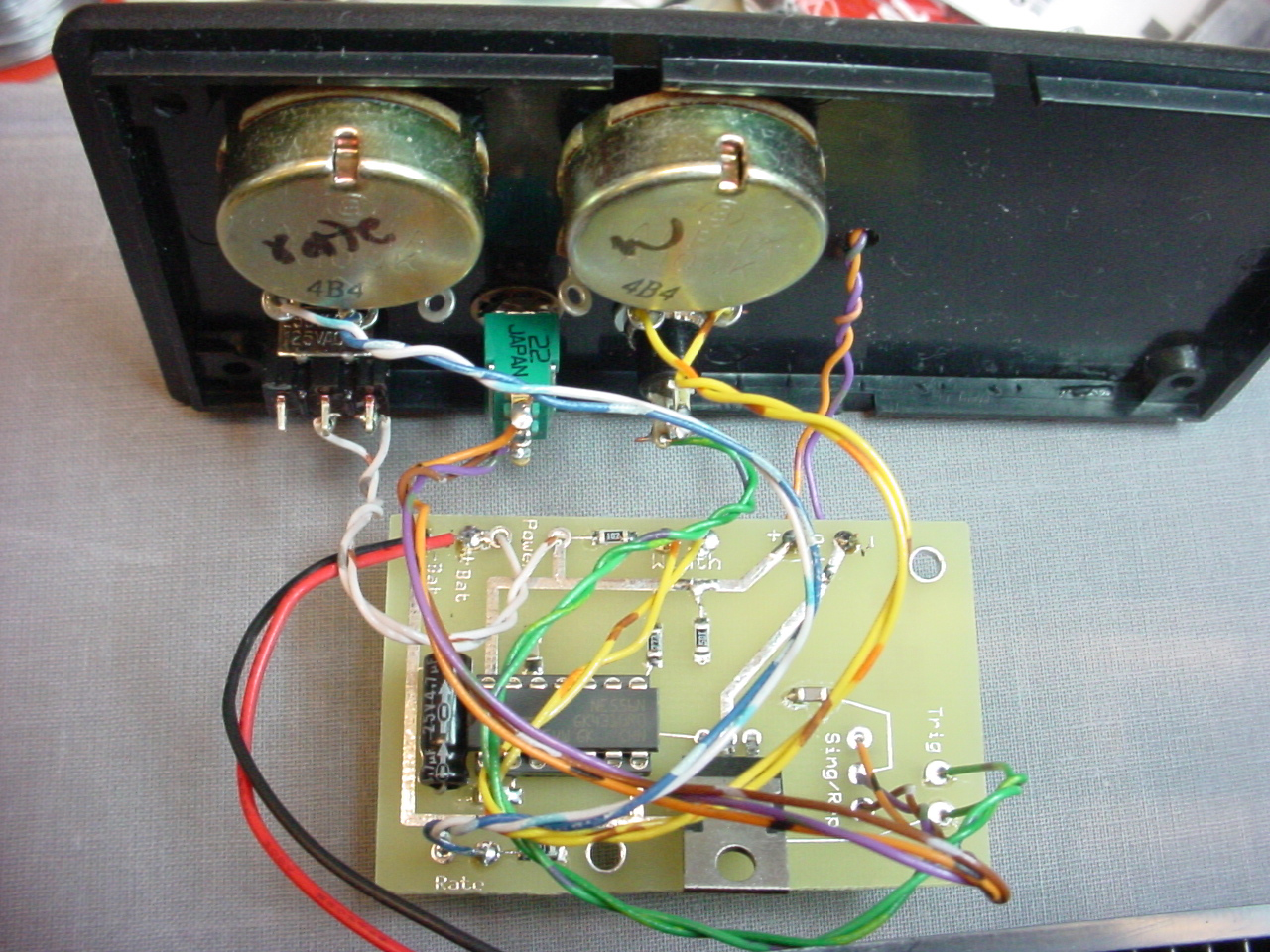
The battery holder was secured by a small plastic strip jammed into the slots on the sides of the box.
 yan
yan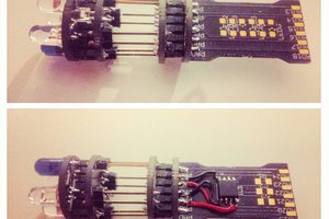
 davedarko
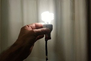
 gregted
 matt thurstan
Hi Bruce, looks like a great project. I'm thinking of using it as an update to my year 9 class strobe project. I'm just a little confused as to whether the 10 ohm resistor is on the PCB or off in series with the lamp? Also a pic of the outside showing the lamp would be helpful. Any information would be greatly appreciated. Thanks.