 Nick Sayer
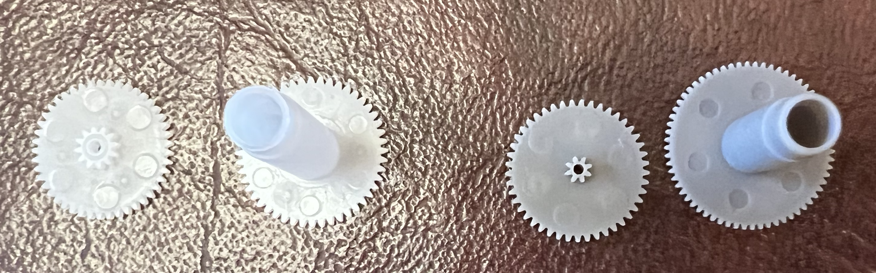
At the end of the gear train of a Lavet stepper motor based clock movement is a gear with a permanent magnet attached to it. The gear sits in a stator with a coil wound around it. The coil is (ordinarily) pulsed at 1 Hz with alternating polarity. That causes the magnet to rotate 180°, which in turn causes the second hand to move 6° (one second's worth).
If you cut the traces on the board that lead to the chip from the battery and to the coil, and then tack on wires to those traces, you can wire in an alternative controller that can make the clock tick any way you want.
If you really want to have the minimum possible impact on how the movement works, it's desirable to reuse the AA battery holder built-in to such movements. Although a single AA battery starts out providing 1.5 volts, as it discharges, the voltage will drop even though it is still capable of putting out enough current to drive the movement acceptably. But a cheap microcontroller, like an ATTiny45, won't operate properly even on 1.5 volts, much less anything lower. Even more critical is the fact that varying the supply voltage may have a detrimental impact on the oscillator frequency. The solution is a boost converter to make a higher, stable voltage out of whatever voltage the battery is producing. The boost converter need only be capable of a burst current of about 5 mA, and most of the time the controller will draw less than 100 nA. This is because we strategically turn most of the internal peripherals off and put the controller to sleep most of the time. The boost converter chip is the XC9140C331MR-G. It's capable of providing at least 40 mA (at 0.8V in), but it remains highly efficient even at the low currents drawn by the crazy clock most of the time. The boost converter circuit is quite small - It's a SOT-23-5 chip, two ceramic caps and an inductor. Because the microcontroller runs at 3.3 volts instead of the original 1.5 volts, we place a 100 ohm series resistor on both outputs. Most of the coils out there have a resistance of around 200 ohms, so the total series resistance of 200 ohms drops the voltage presented to the coil down to close to the original 1.5 volts. The flyback diode array is just outside of series resistors. The flyback diodes prevents the negative coil collapse voltage from being presented to the controller, which would potentially damage it.
We use the AVR's "idle" sleep mode, because we use a timer interrupt to wake the controller at 10 Hz, and idle mode is the deepest sleep available that allows the timer to run. Every time the controller wakes up, it makes a decision whether to tick or not and then goes back to sleep.
The timer is driven by the clock's 32.768 kHz crystal. Because that crystal is also the controller's execution clock, it takes very little power even when it's not sleeping. But obtaining a 10 Hz interrupt source from a 32.768 kHz source requires some tricky arithmetic. The timer is configured with a divide-by-64 prescale setting, resulting in a 512 Hz counting rate. To go from 512 Hz to 10 Hz we must divide by 51 1/5. To do that, we count to 52 once, and then count to 51 four times. Some of the intervals will be about 2 ms longer, but for this application, that's not significant. The only downside to having such a slow system clock is that the ISP programming clock must be no faster than a quarter of the system clock, so programming must be done at no faster than 8 kHz. Most of the firmware is just a little more than 1KB, so it takes upwards of 15 seconds to load.
The accuracy required to keep a clock reasonably close to the correct time is quite demanding. Even a pedestrian standard of 10 parts per million (about 26 seconds in 30 days) requires at least calibrating each manufactured batch of boards. The result of the calibration is a standard average drift factor. Each individual board can be expected to run within 10 parts per million of this standard drift due to the manufacturing tolerances of the crystal, but...
Read more »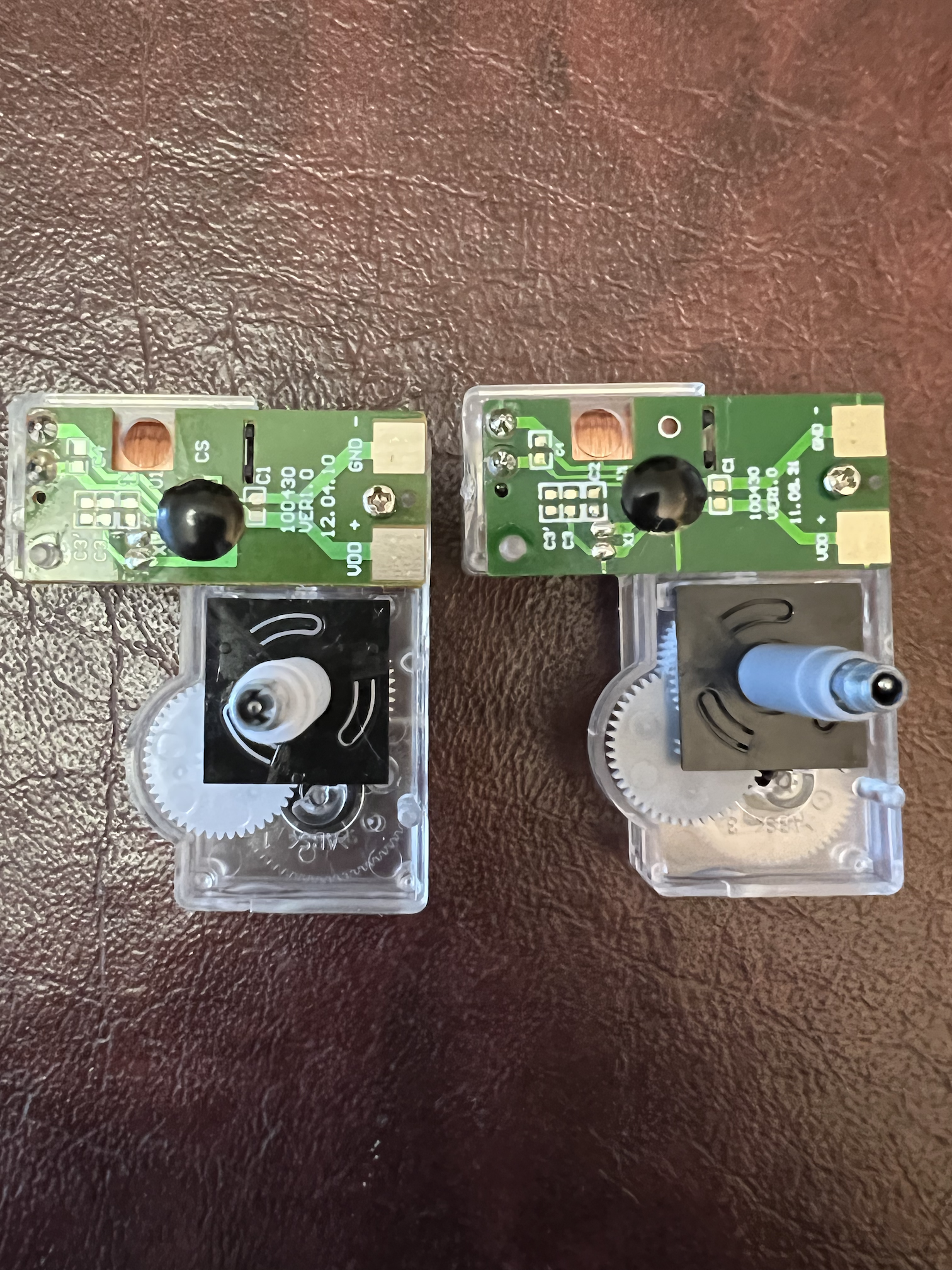


 Gary Marsh
Hmmm. Now I want to put an ESP8285 in my clocks for time synchronization and auto DST adjustment.