 Ossum
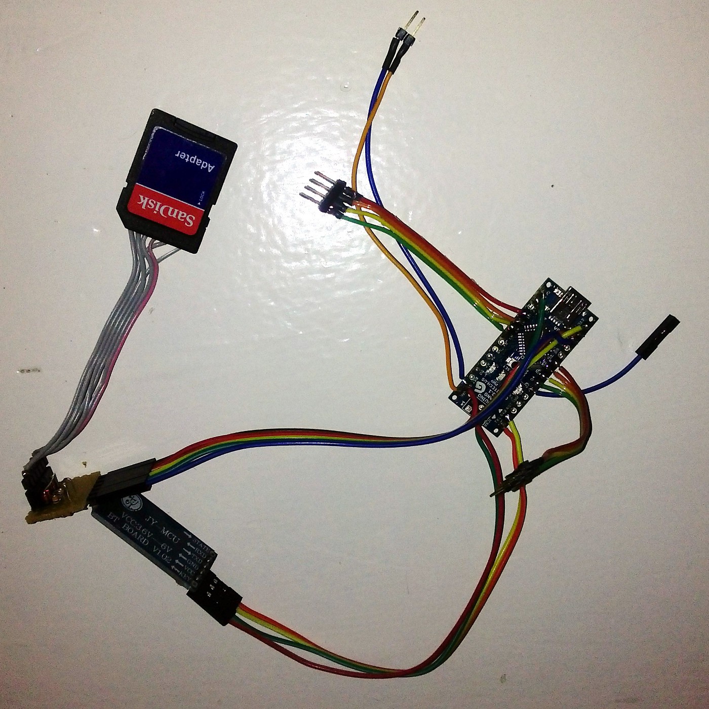
OssumThe original robot toy just had one motor driving the same walking/spinning/waving actions over and over again. We removed the guts of the robot replaced with rechargeable batteries, an Arduino Nano, Bluetooth, a Laser, speaker, SD card, LEDs and far too much rainbow ribbon cable, resulting in a an upgraded robot controllable from an android phone. He also curses a lot more than the original, but we tried to keep the videos suitable for work.


 Testing the power distribution board is working, feeding it from a supply and checking the current draw.
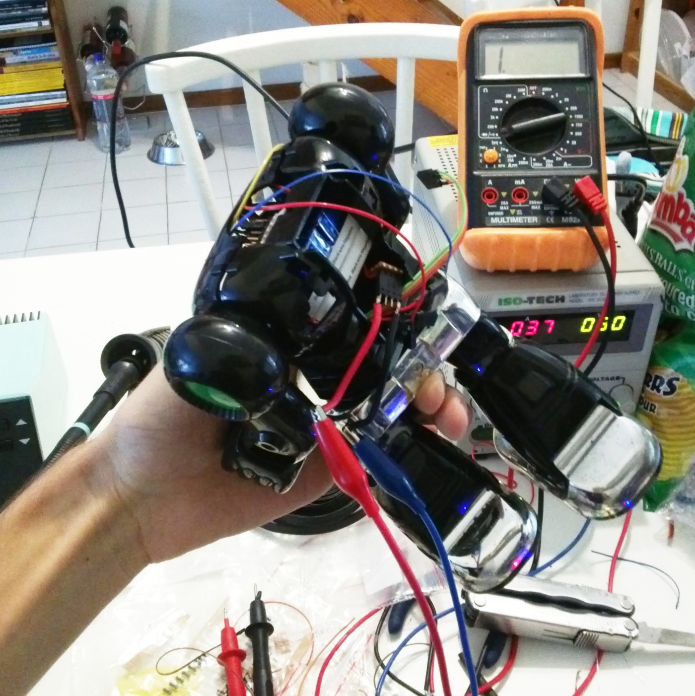
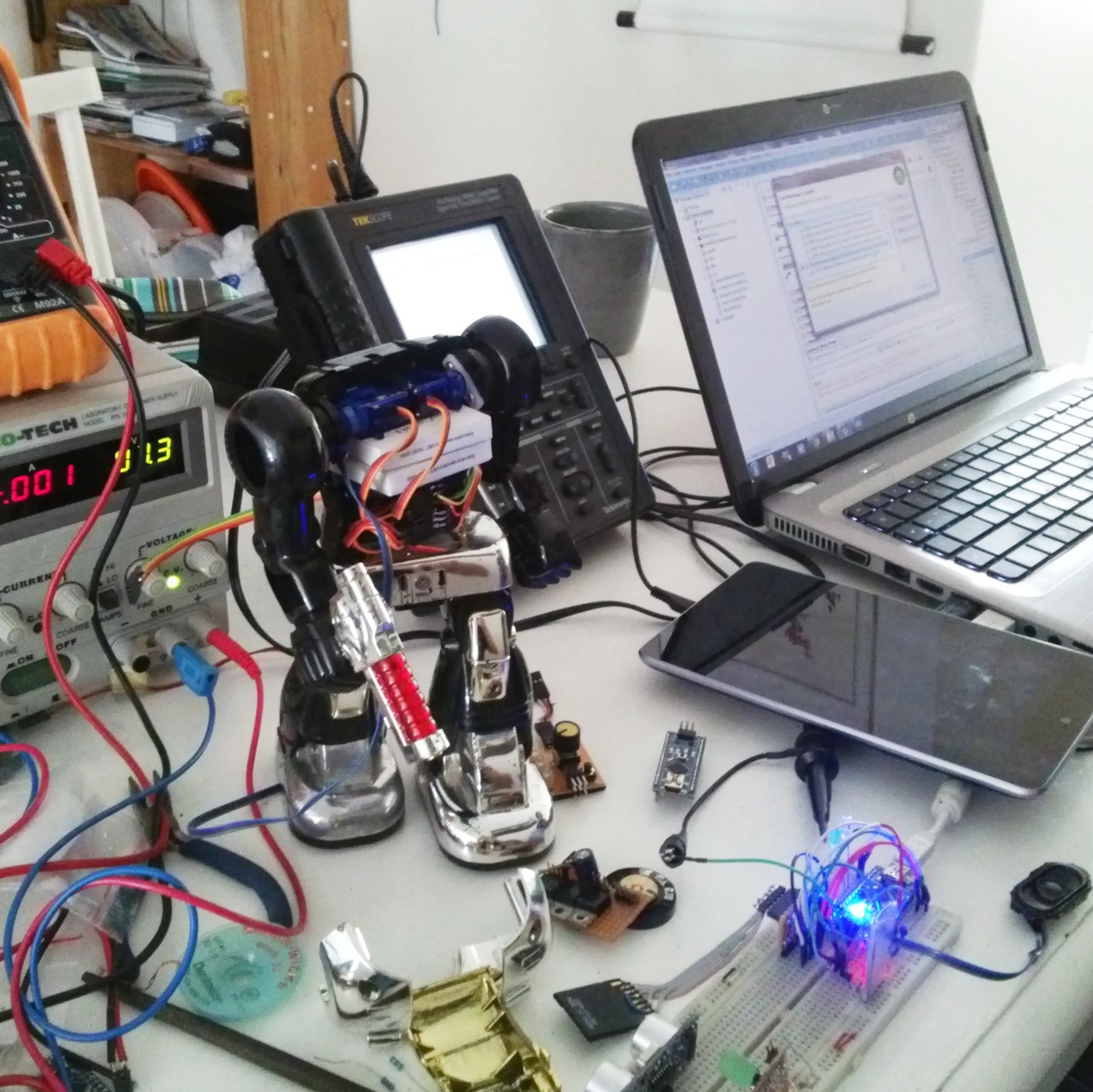
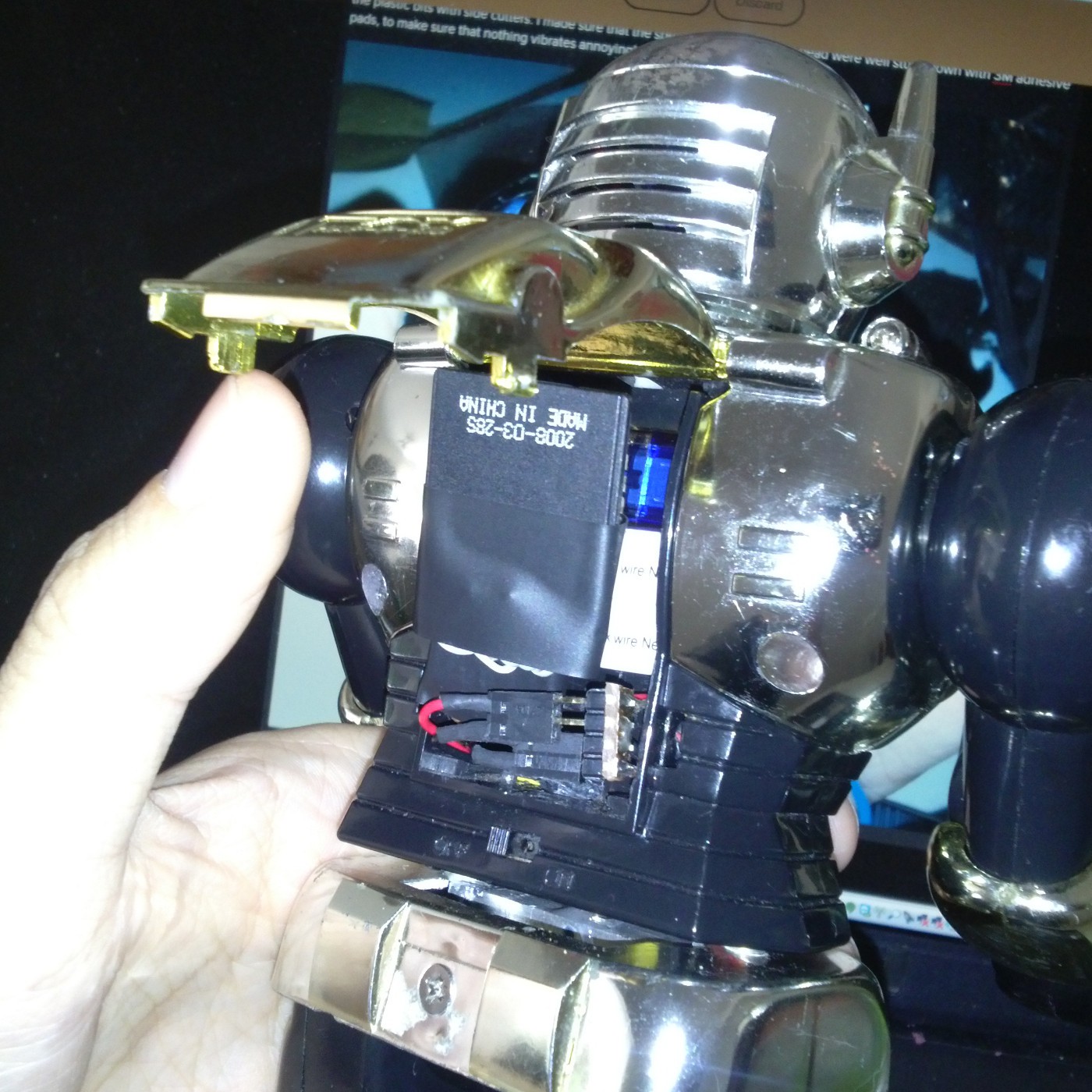
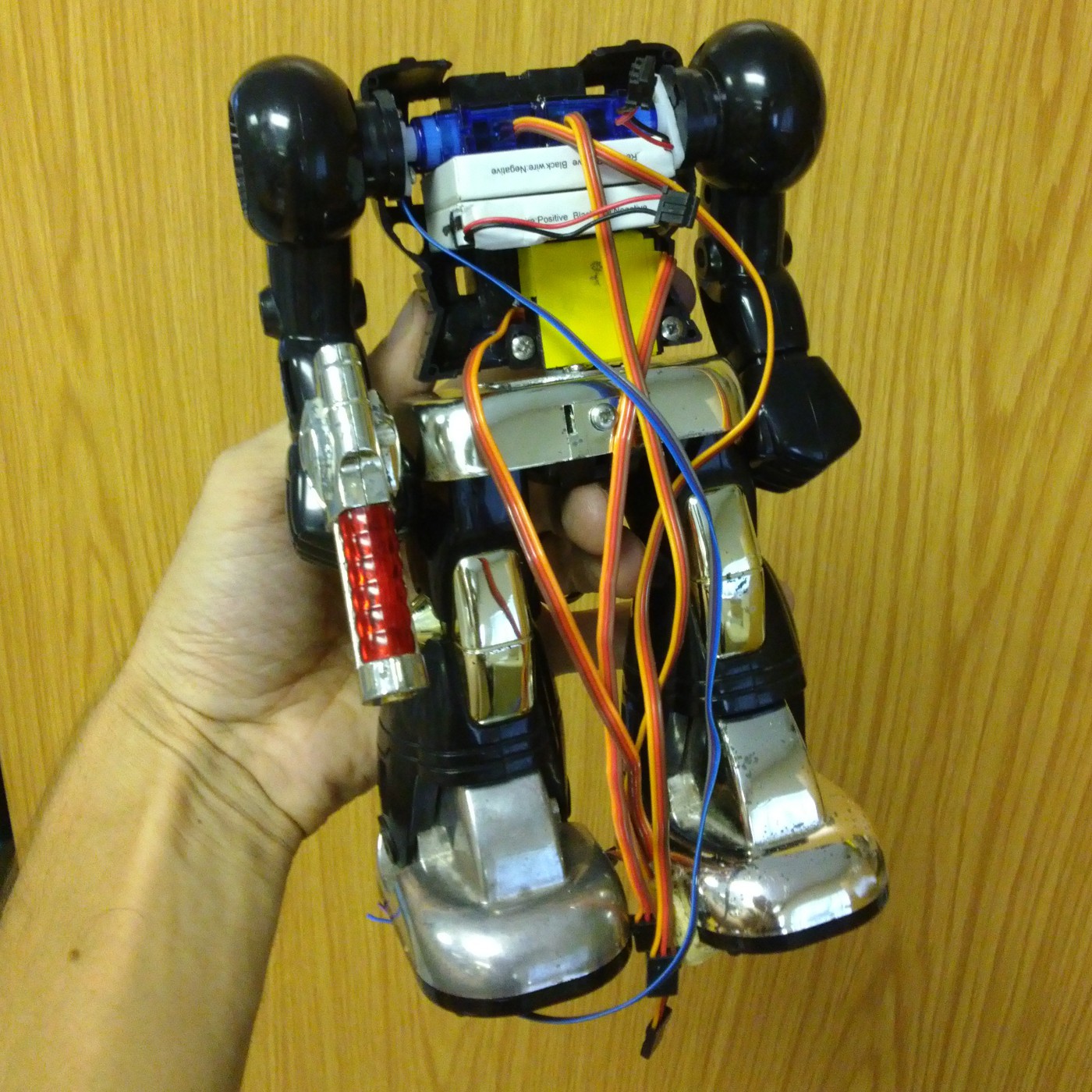
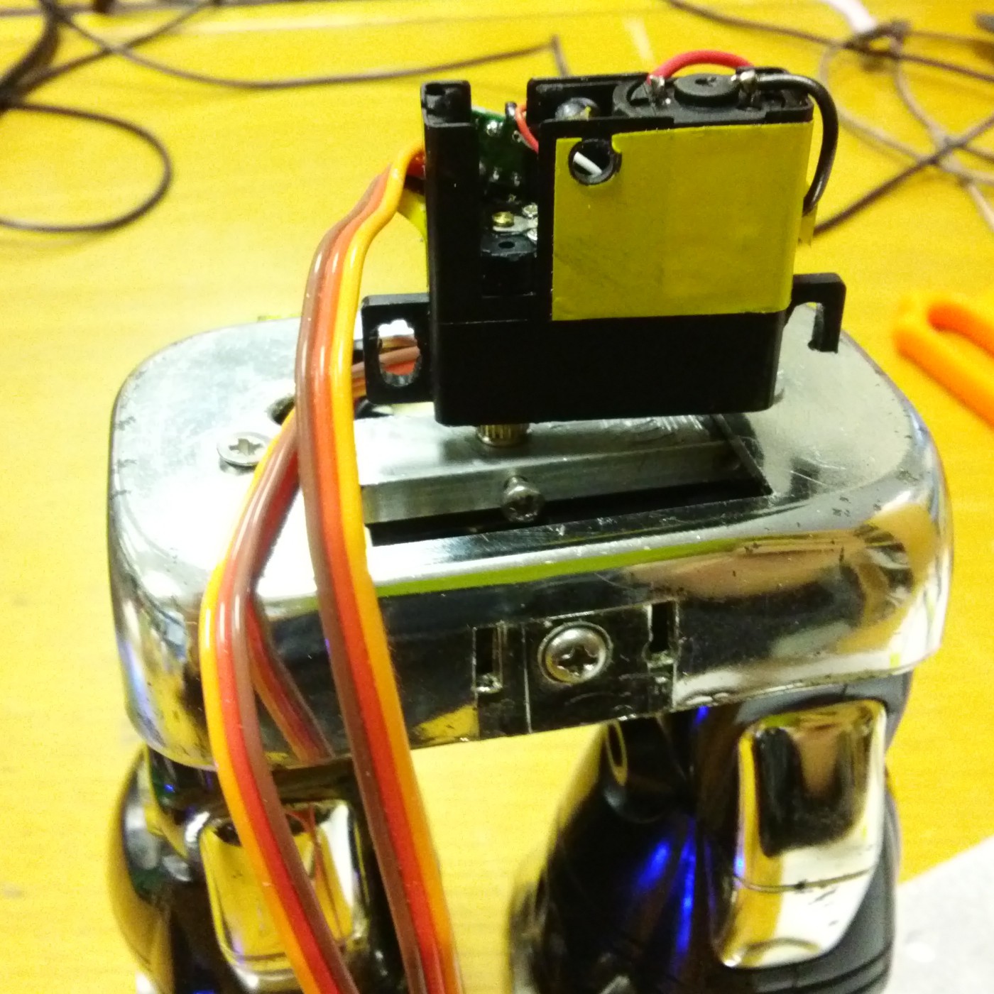
 By 2:30AM this morning things were starting to look a bit neater, most of the cables have been trimmed to their final lengths and the chest plate can bit fitted on (barely!).
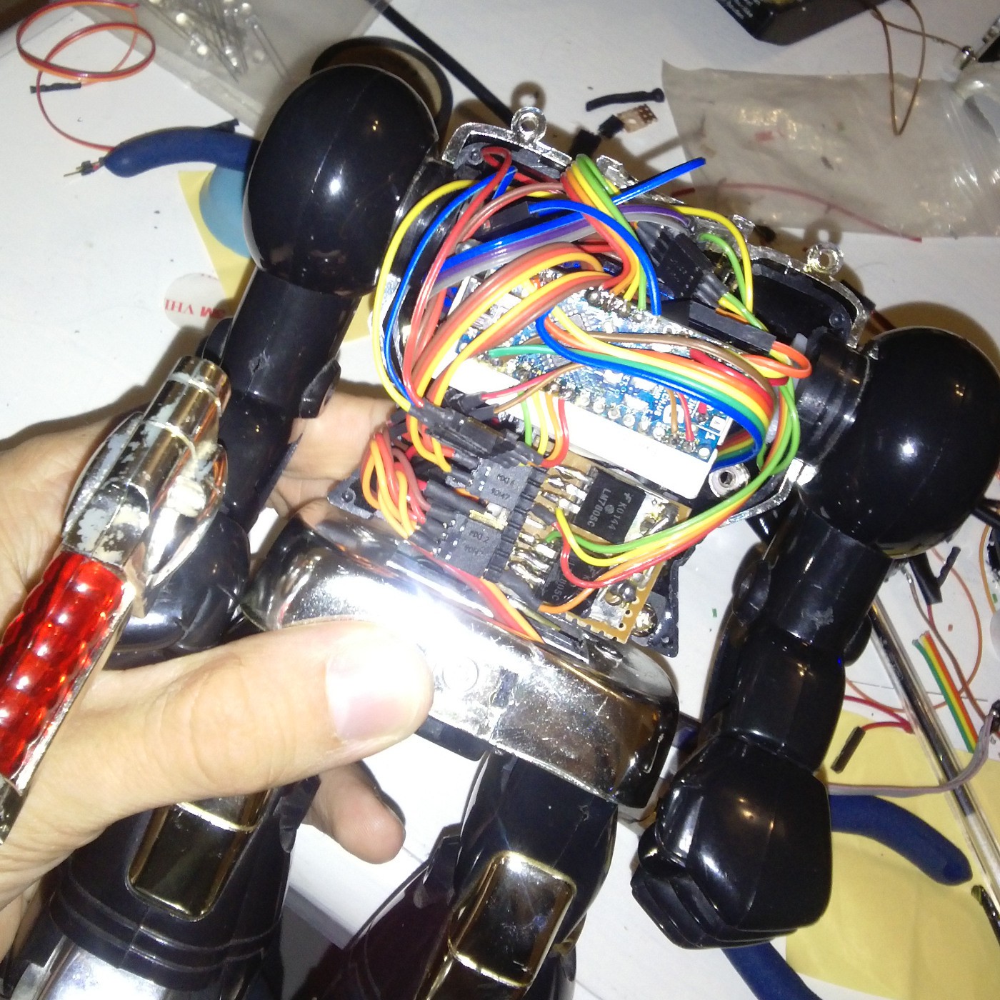
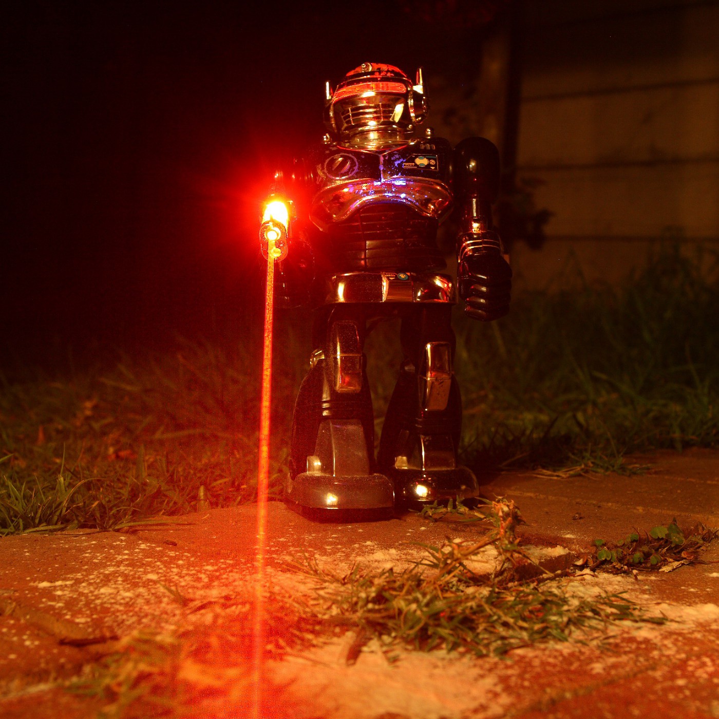
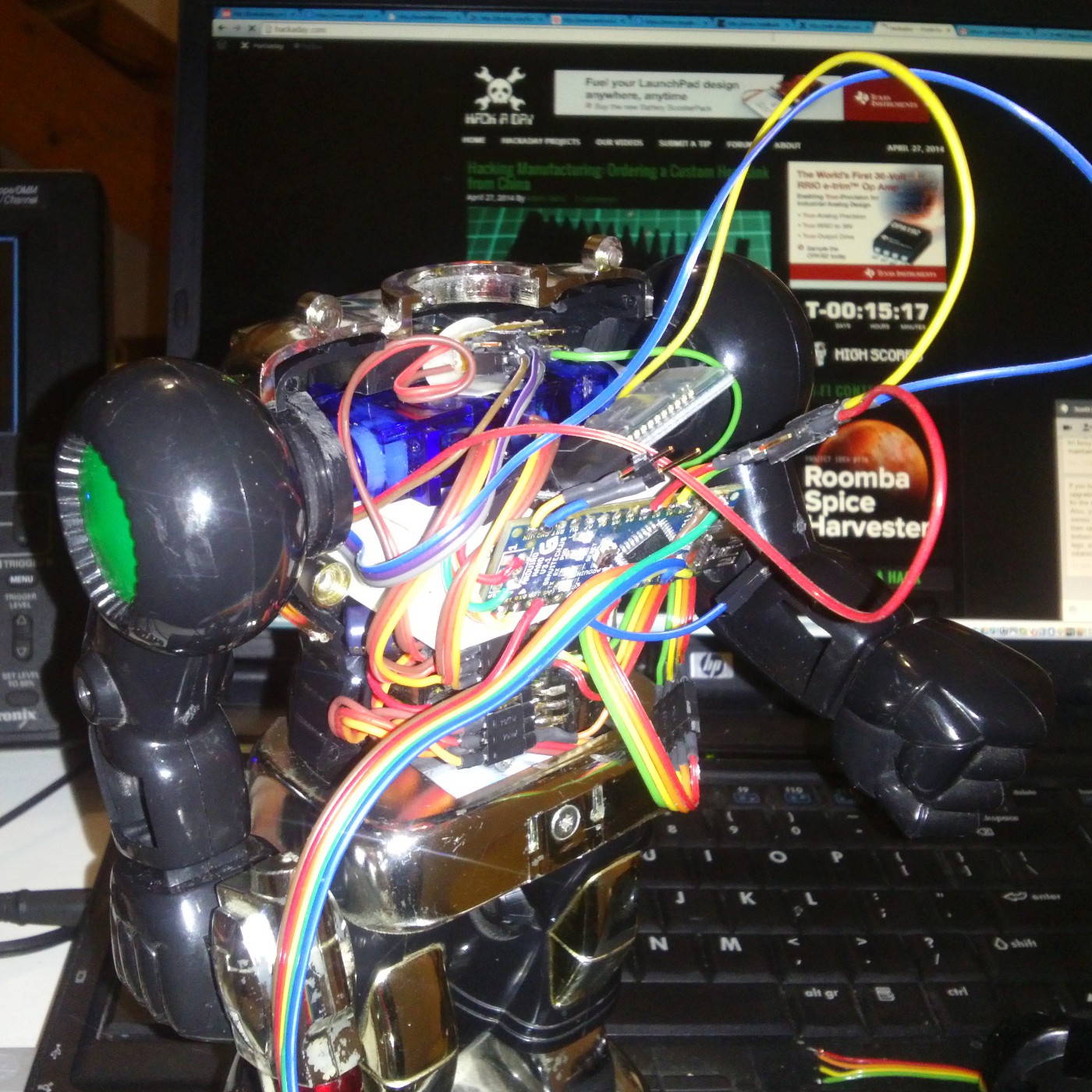
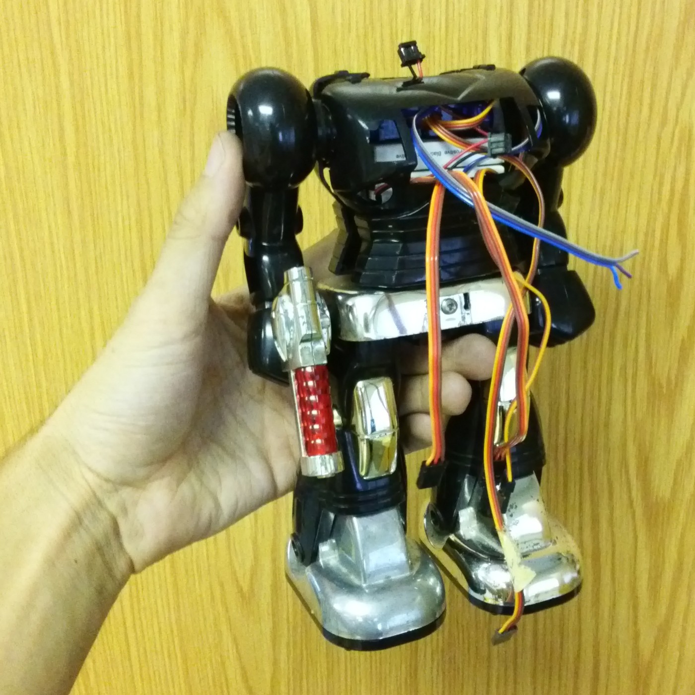
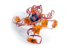
 And here he is, complete, all trim re-installed, looking like his good old shabby self, yet stuffed with modern technology! I will get some video tonight, but I would say we can call this project done. At least for now!
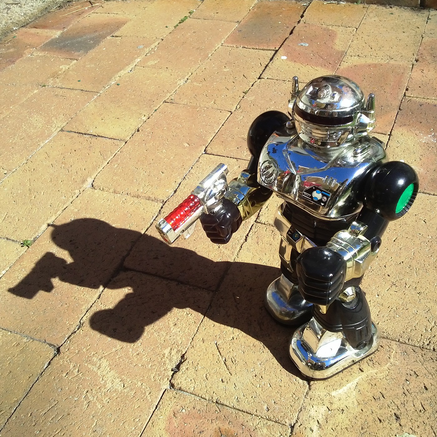
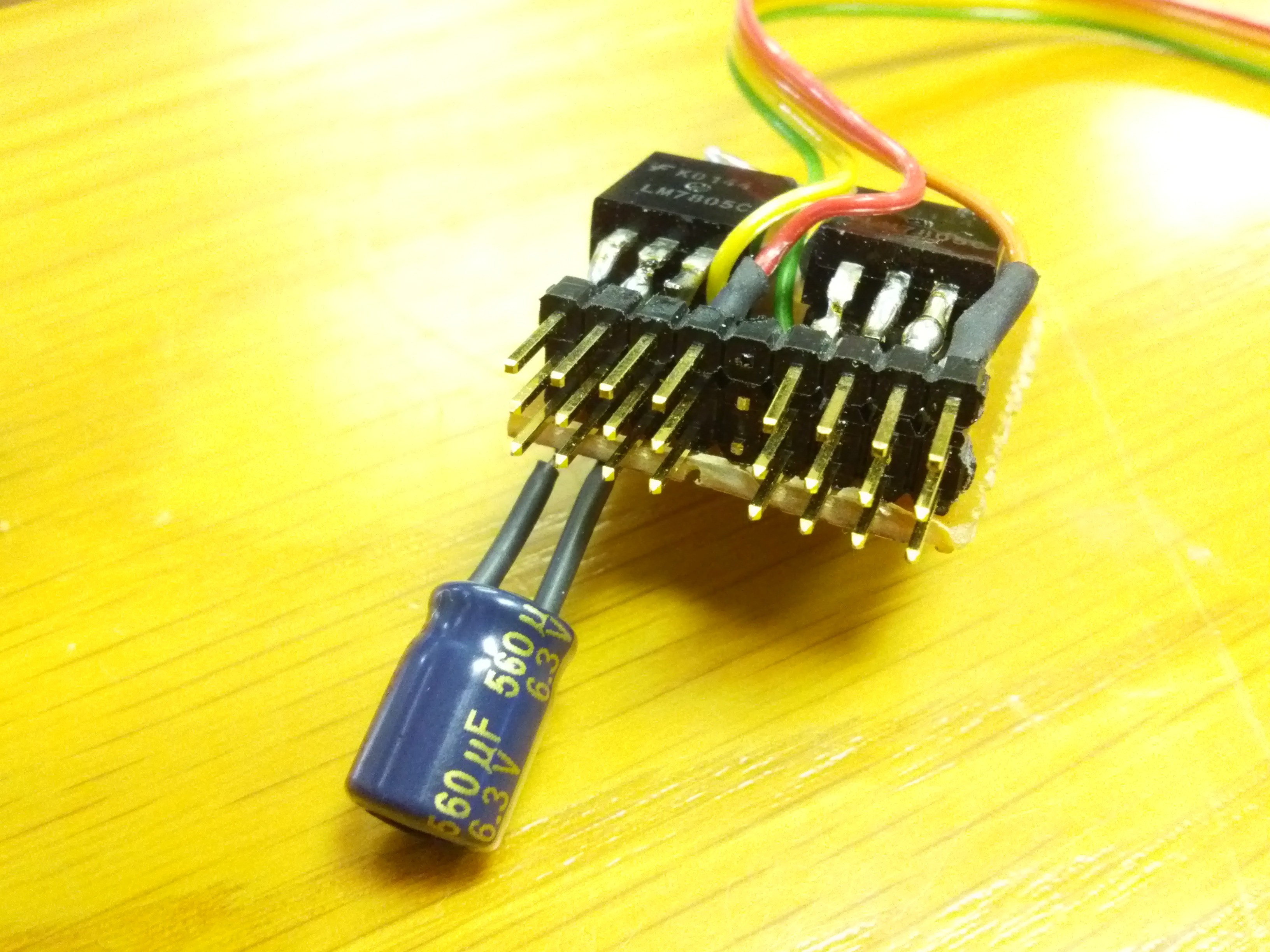
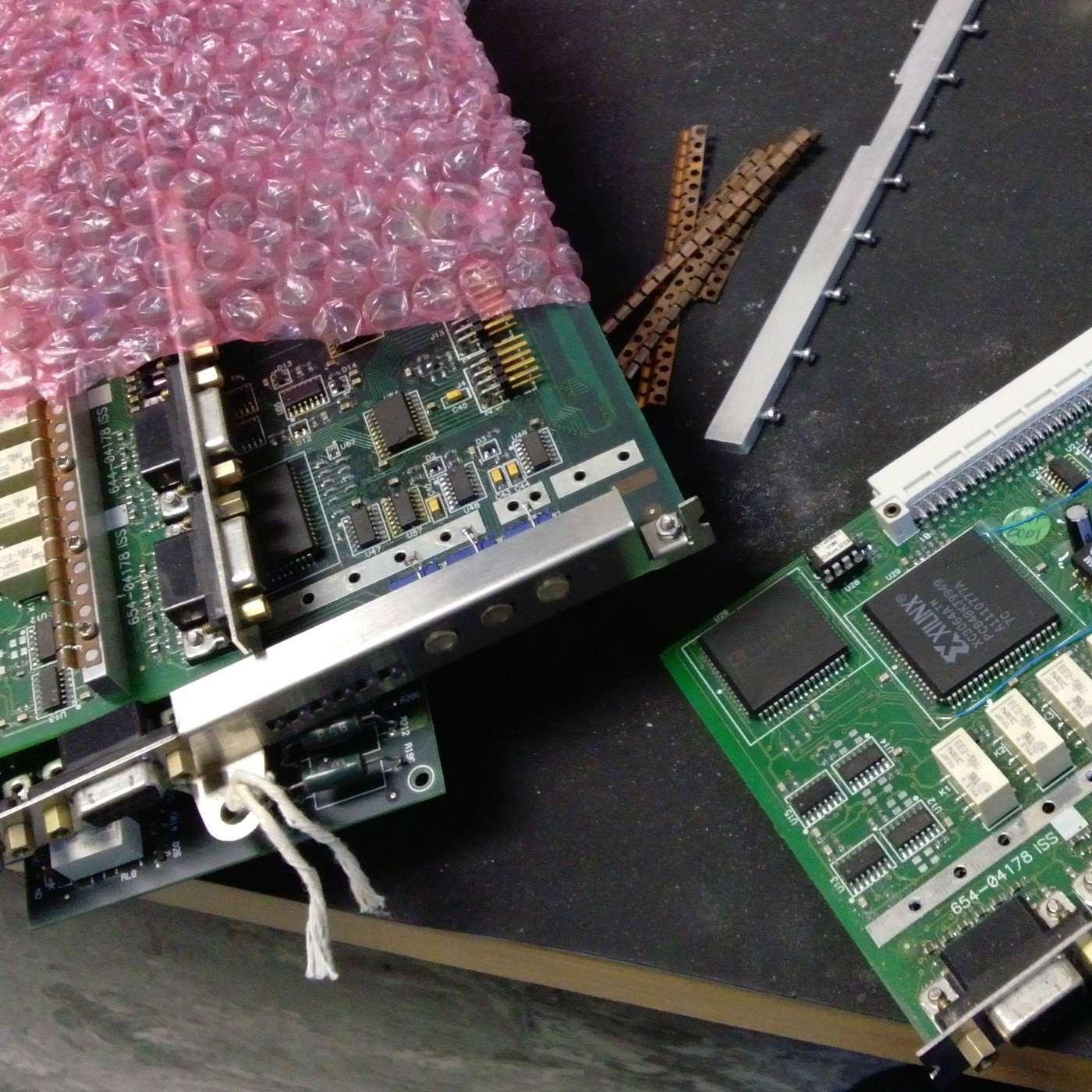
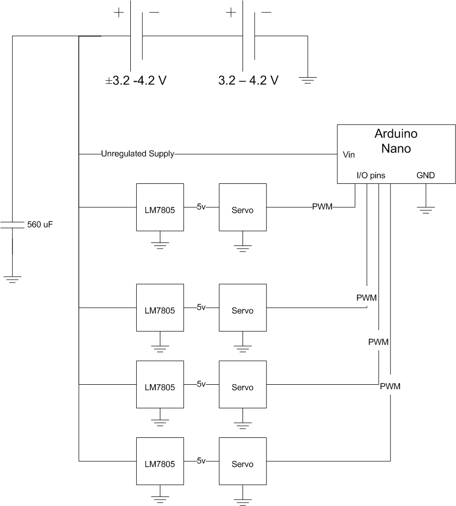 My first attempt was too bulky to fit into the torso, so I remade it into what you see below. The bottom two rows are in series, which gives me extra pins to take off regulated or unregulated supply as needed.
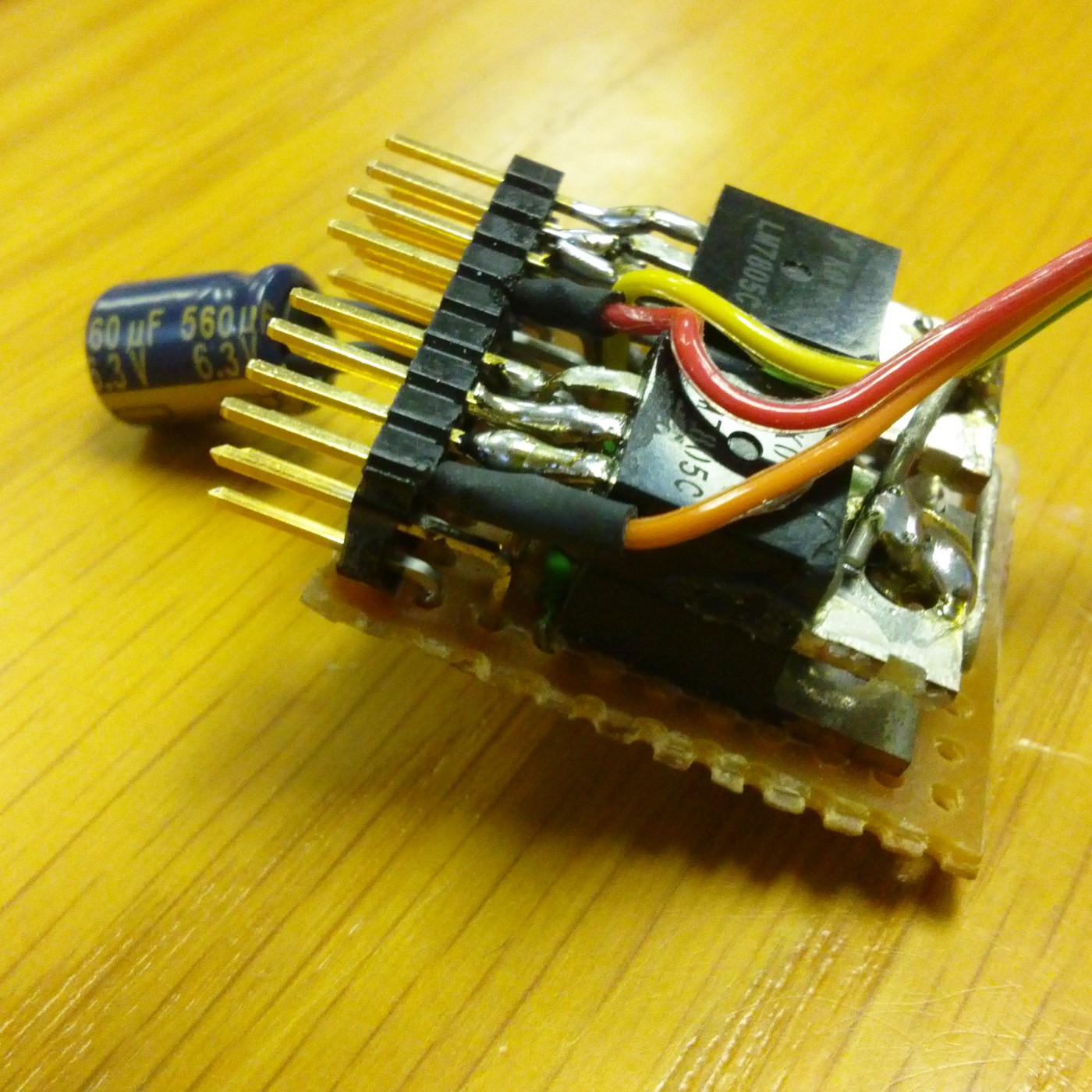
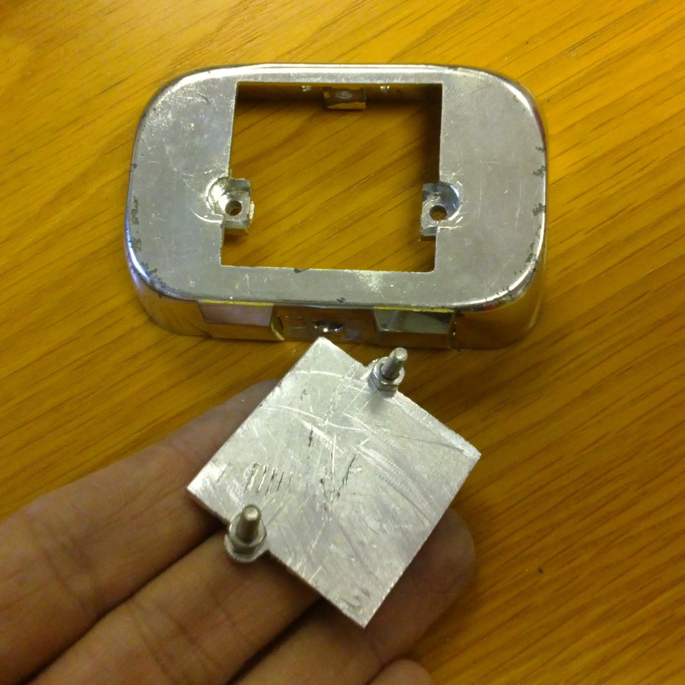
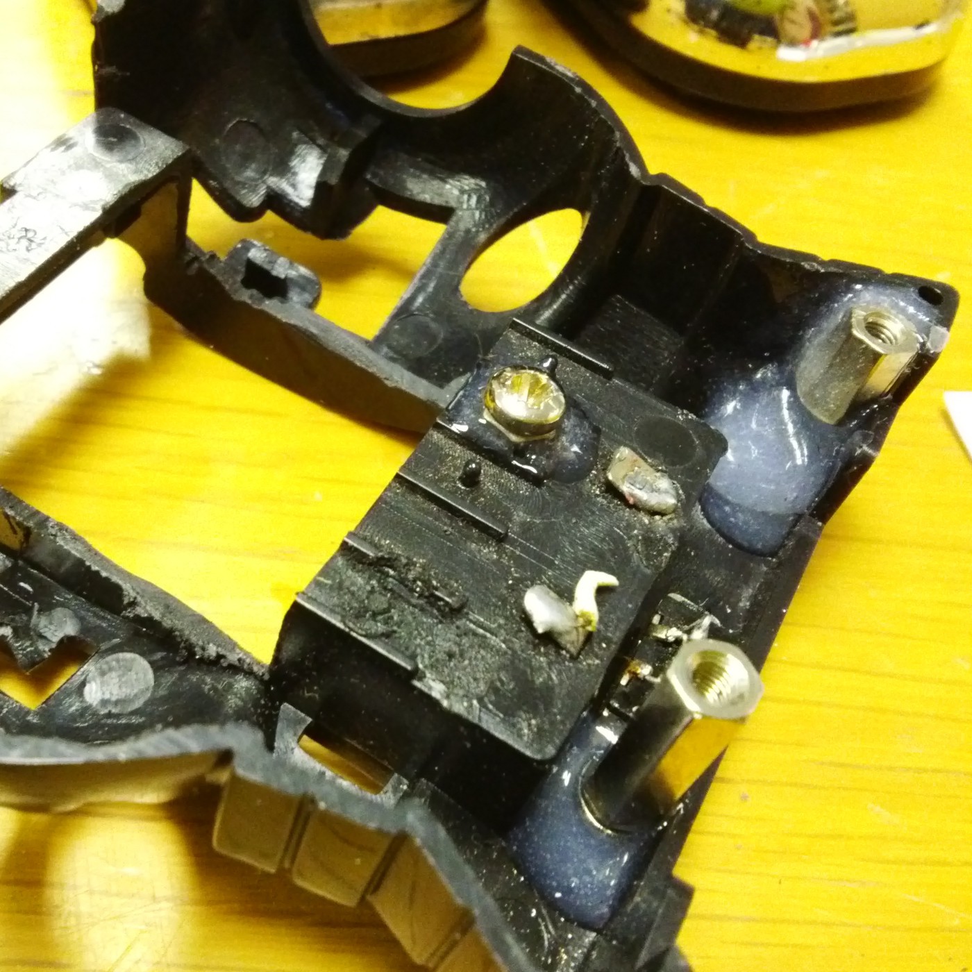
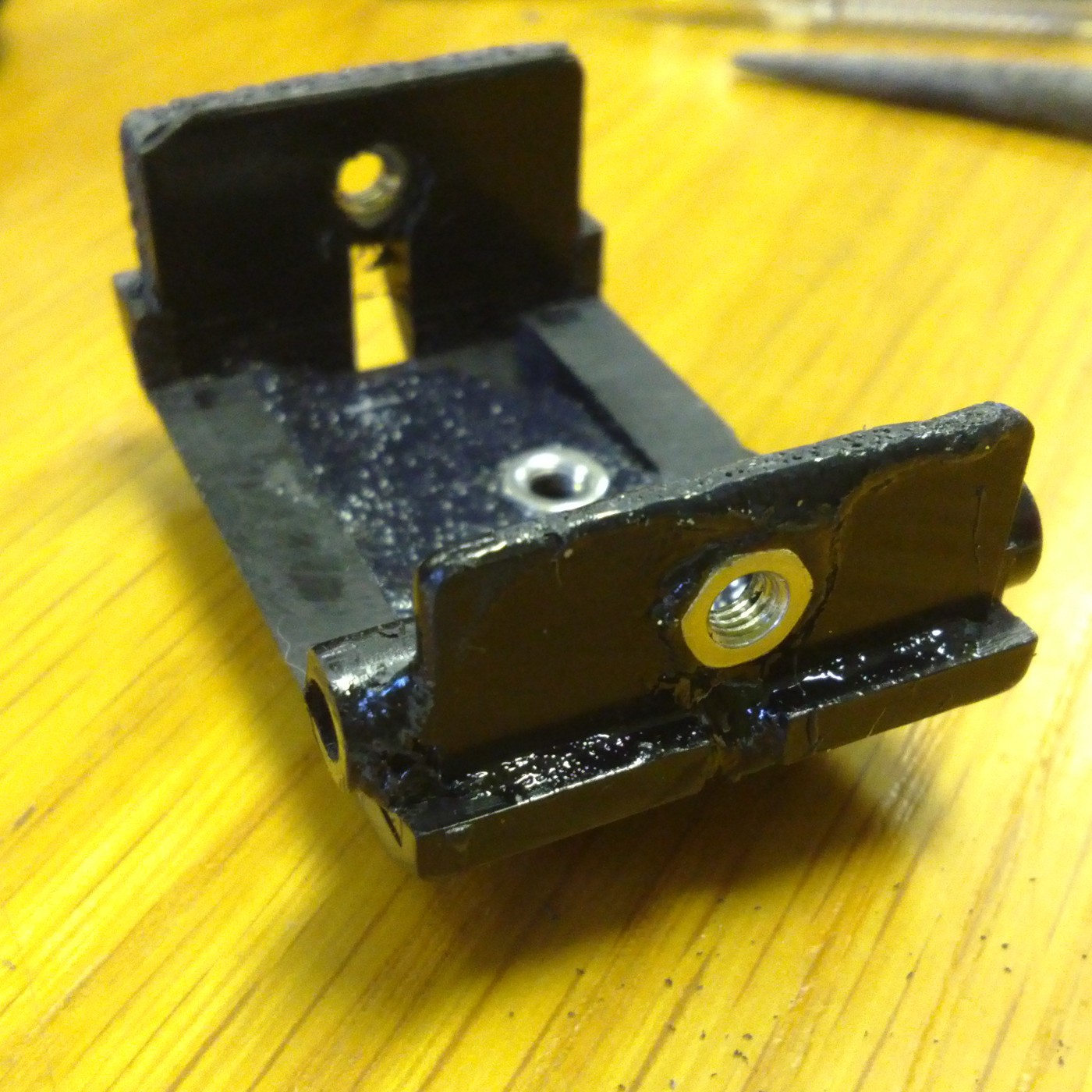
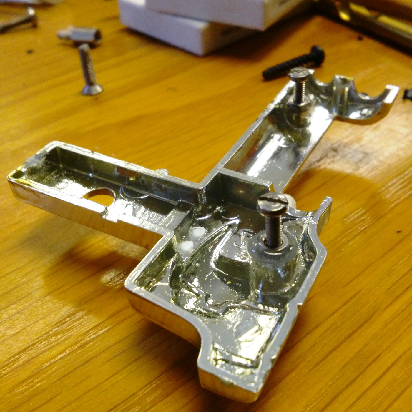
 Here are other things that have been going on in the background too, such as setting a pair of nuts into the pelvis, since the original fasteners were just screwed into
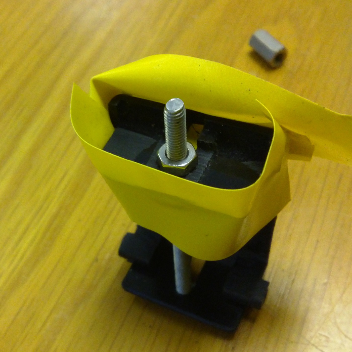
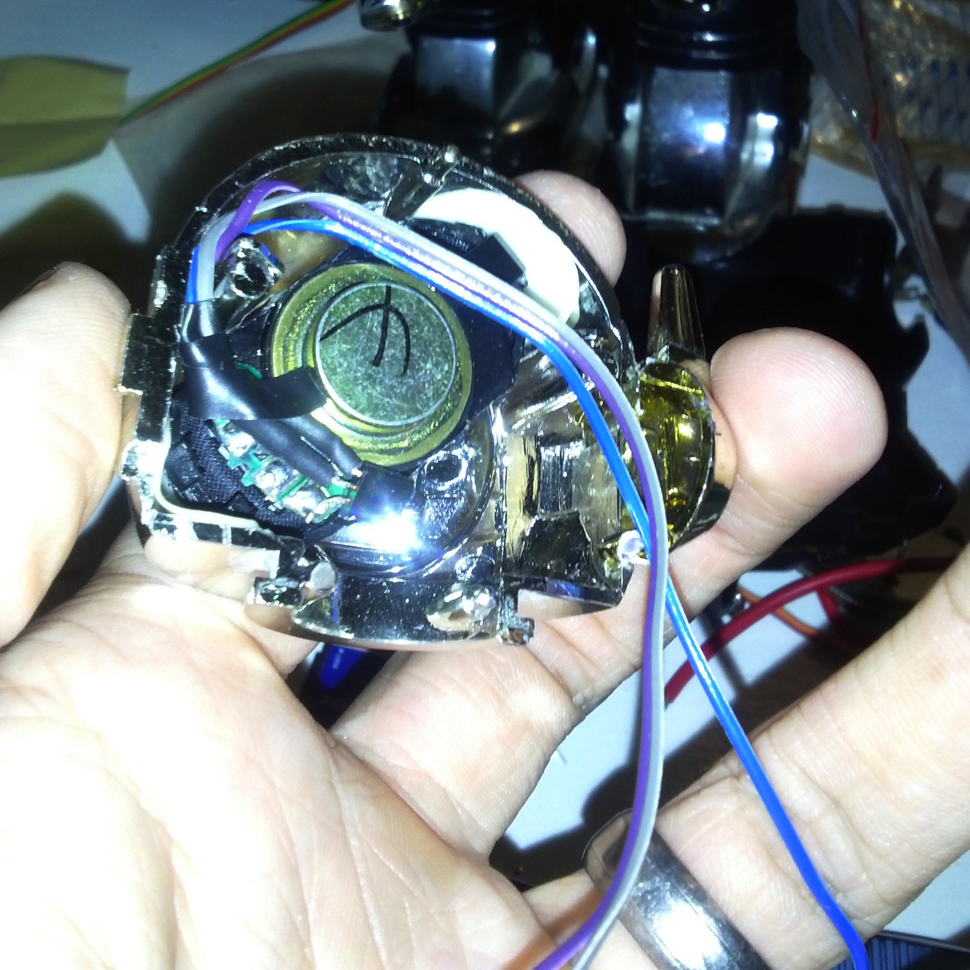
 I popped in a current limiting resistor (although it has a 33 ohm in series already, it is designed for a 3V supply, so a bit more resistance was required) and got this result:
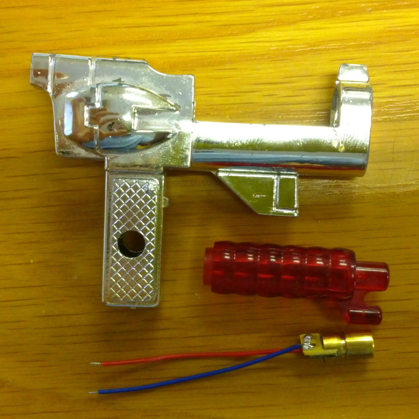
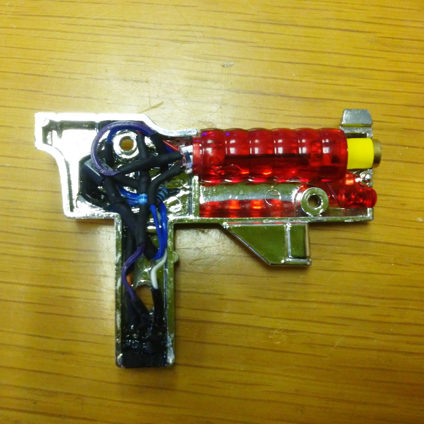
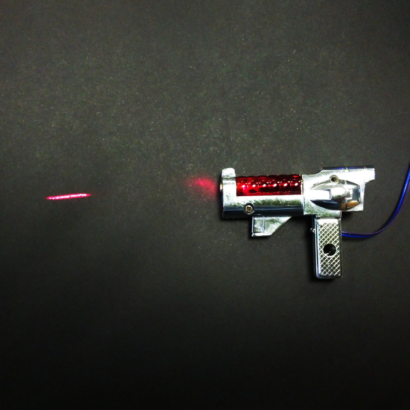 That is pretty cool, but it would be a lot better if the gun itself still lit up, so I opened it up again and put in a bright red LED to light up the barrel.
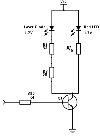
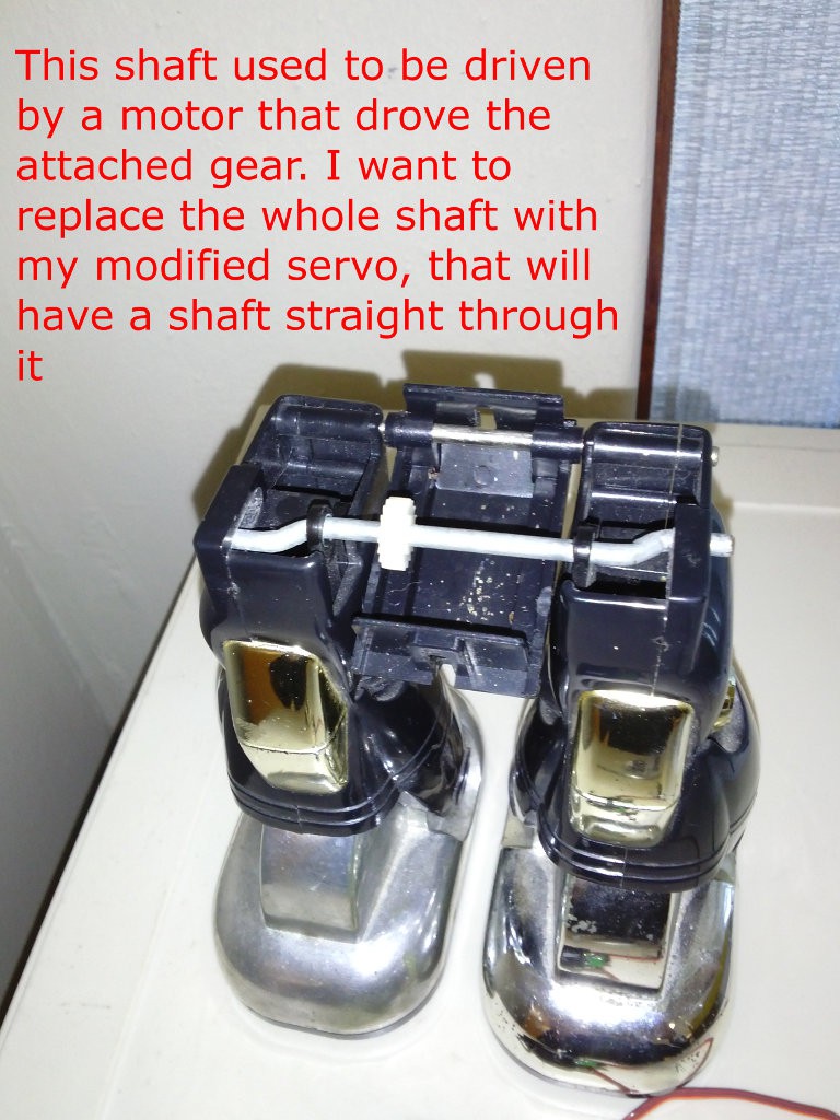
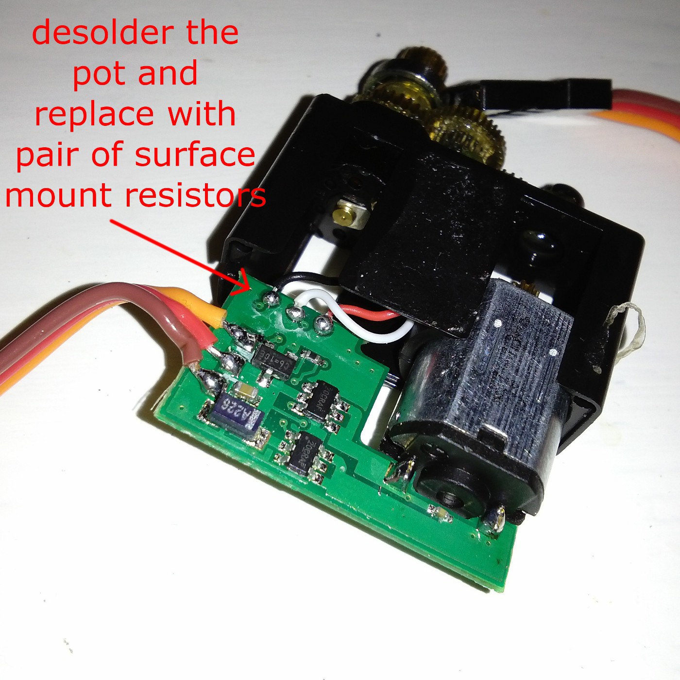
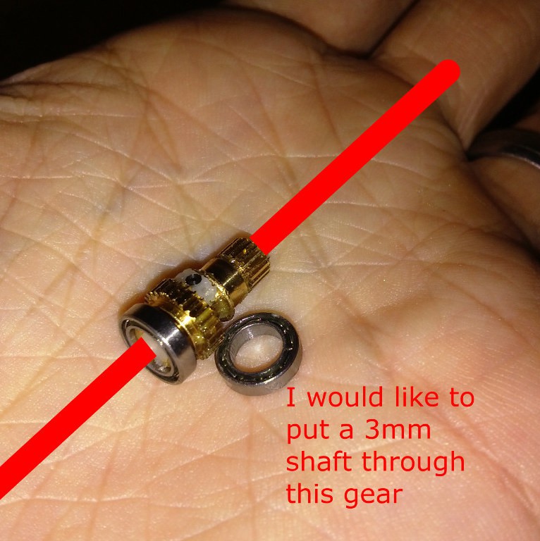
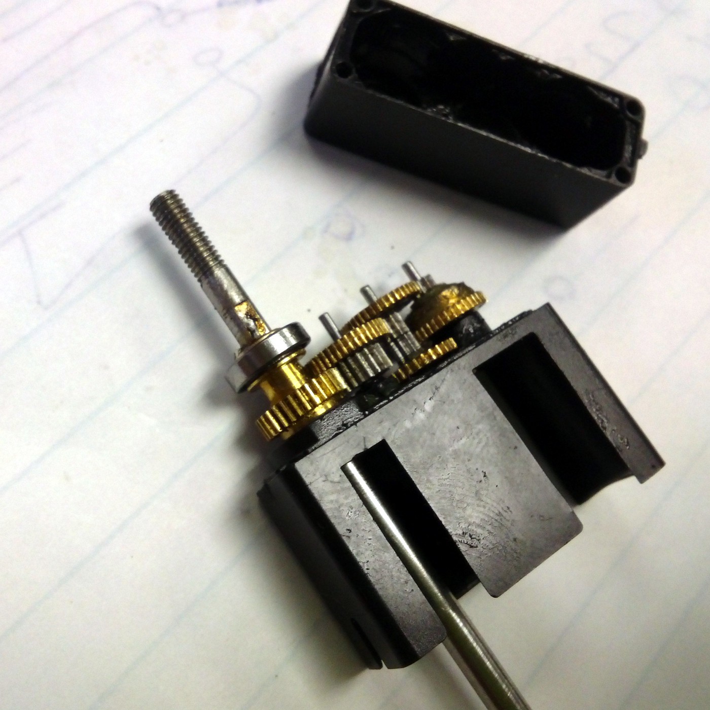
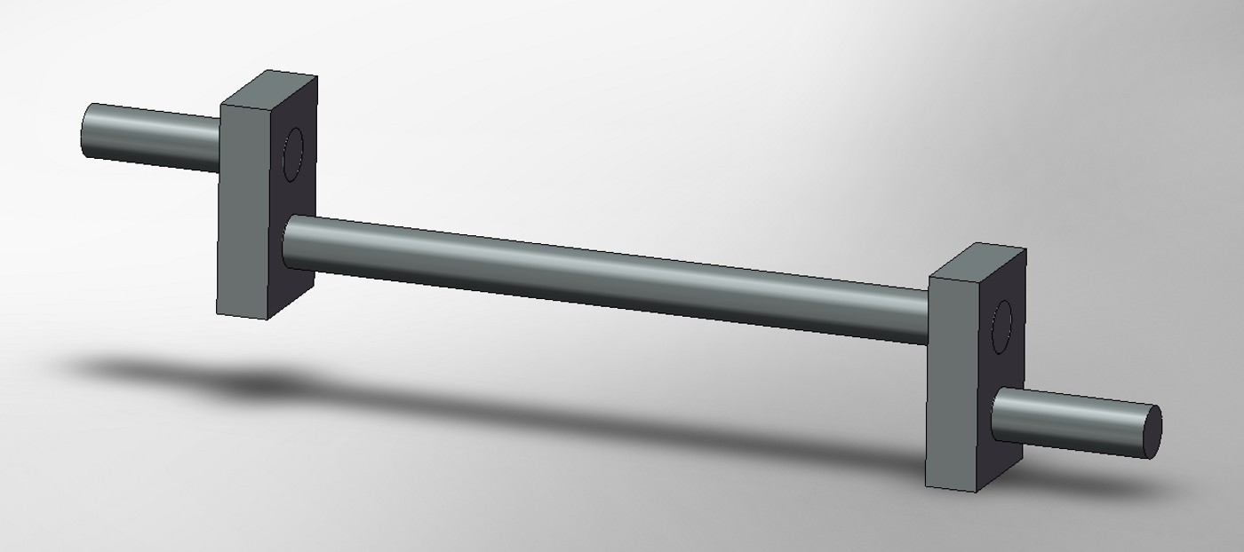
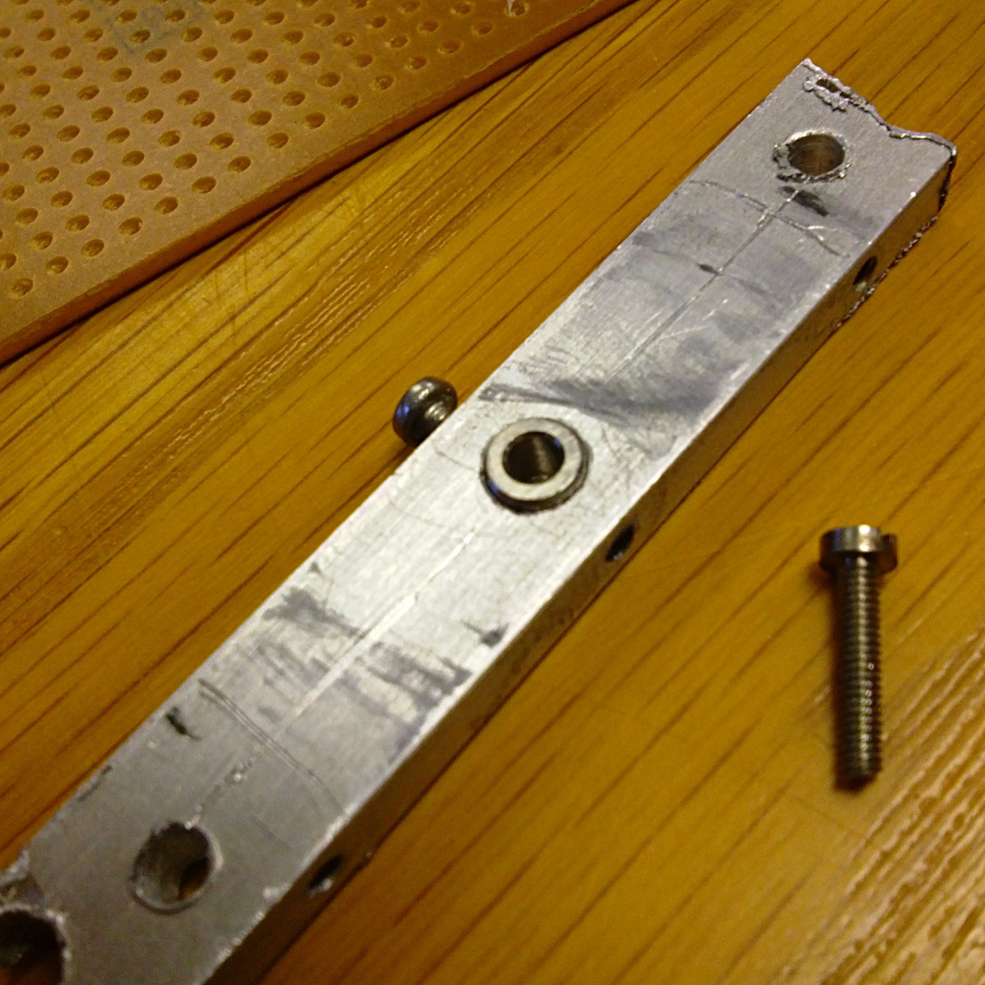
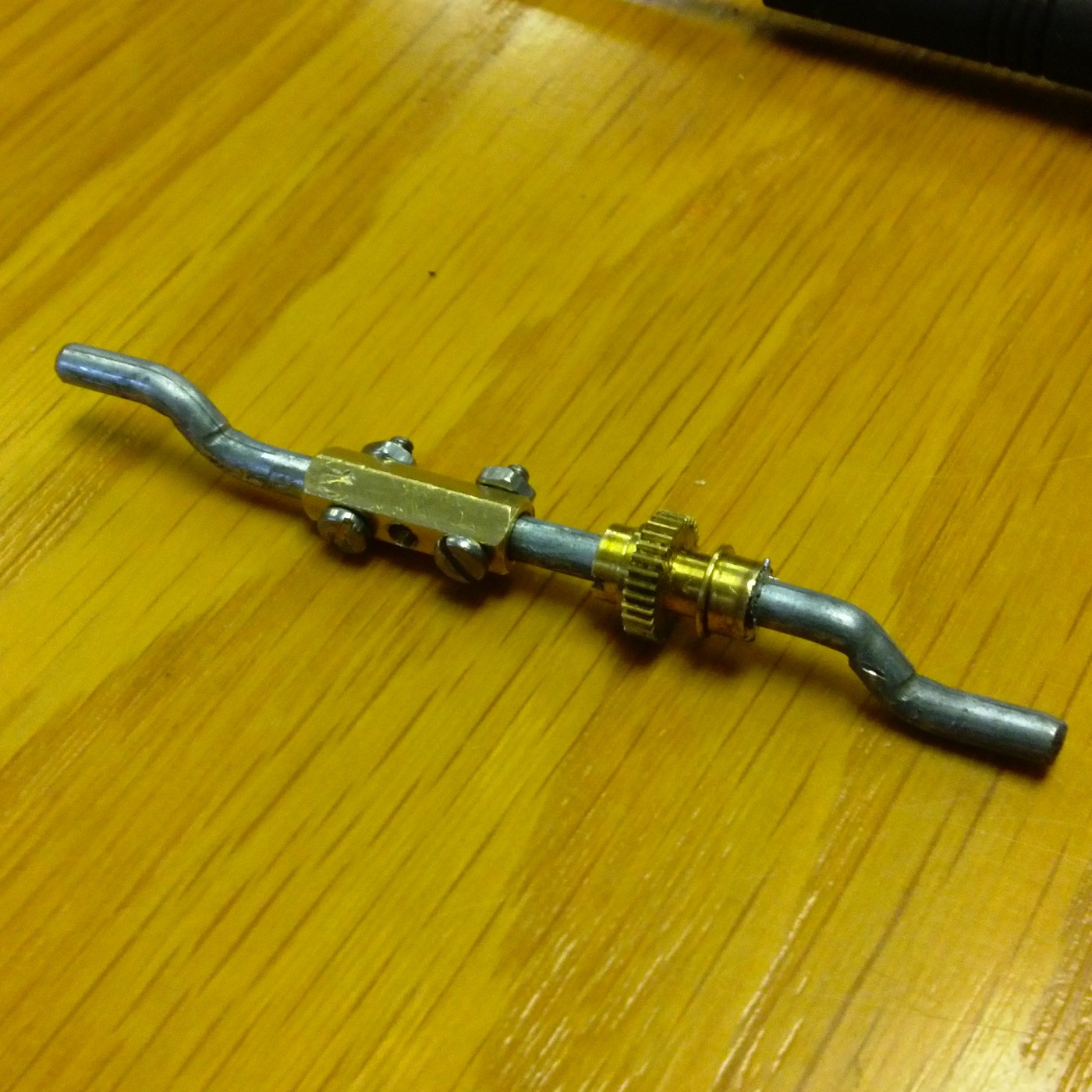
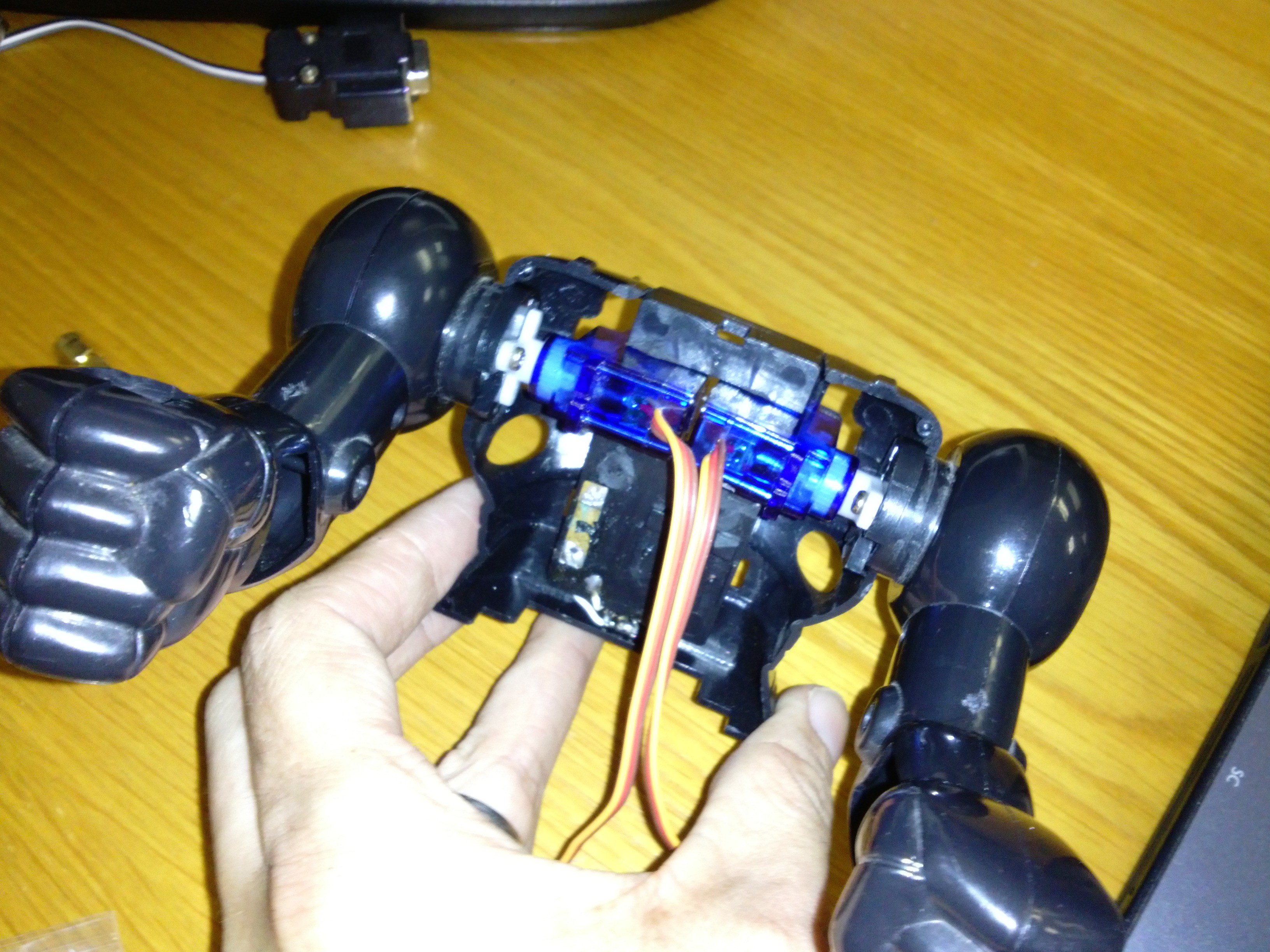
 After staring at it all for a while I went a new direction. If I could cut the original shaft in half, put it through the servo gear and then reassemble it, all would be well. I would drill two holes in the shaft, then put a sleeve with matching holes over it and screw it all together. Unfortunately the drill slipped off the shaft, even though I had filed a flat spot to try and prevent this, and kind of cut it in half.
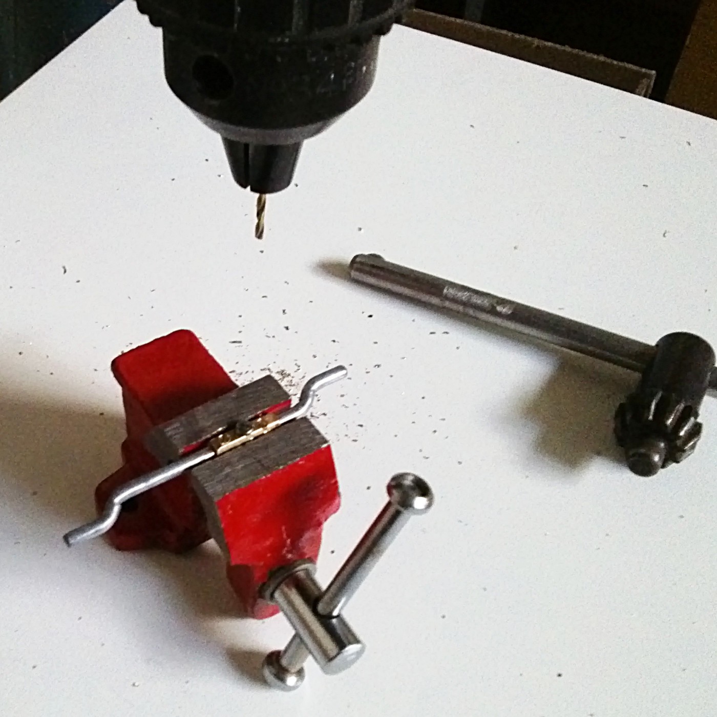
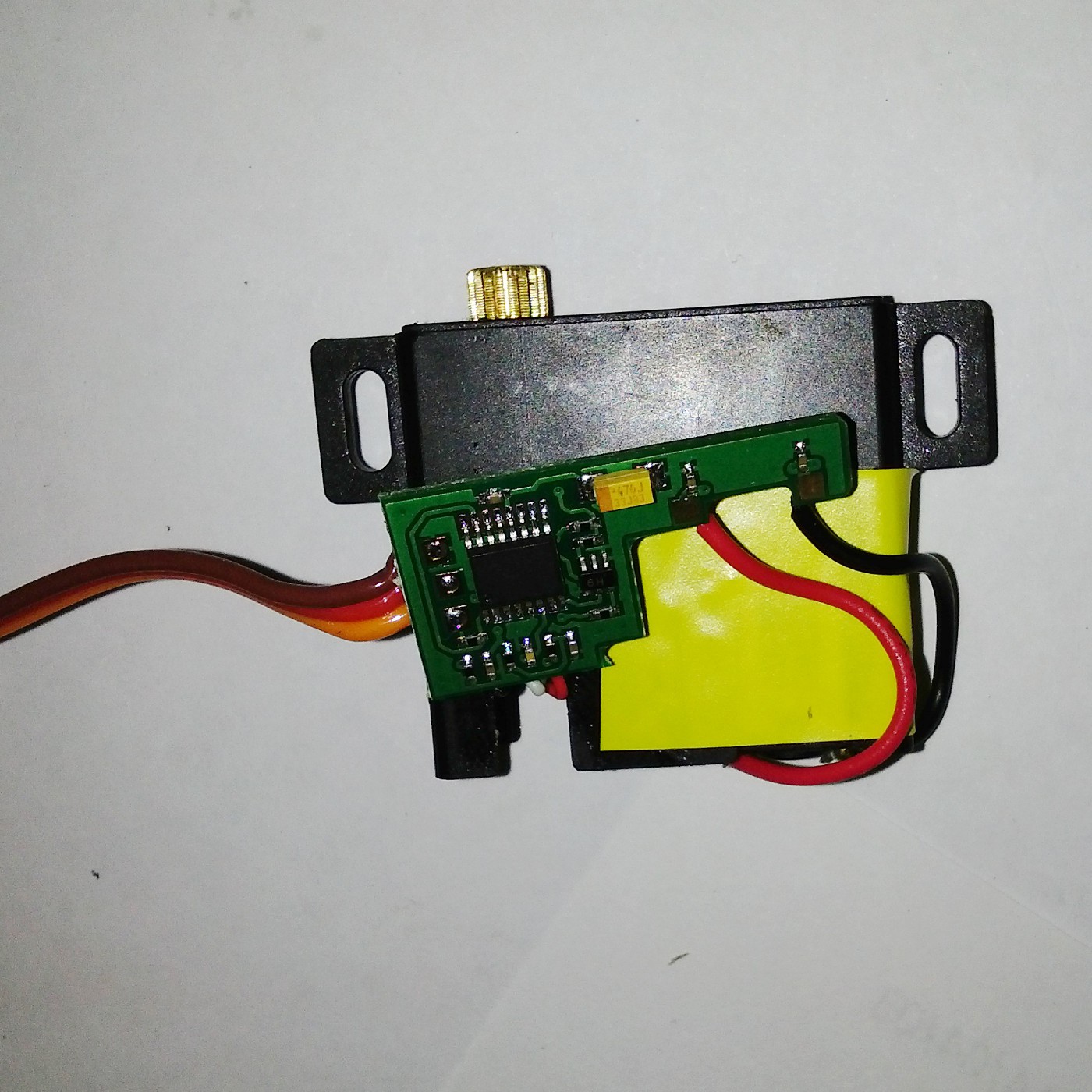
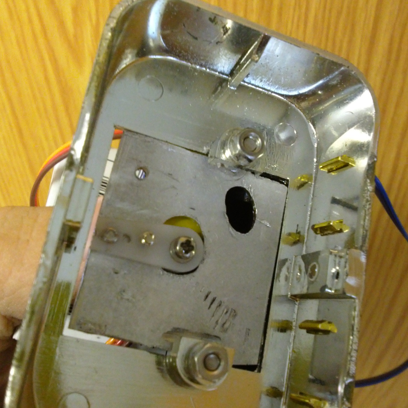
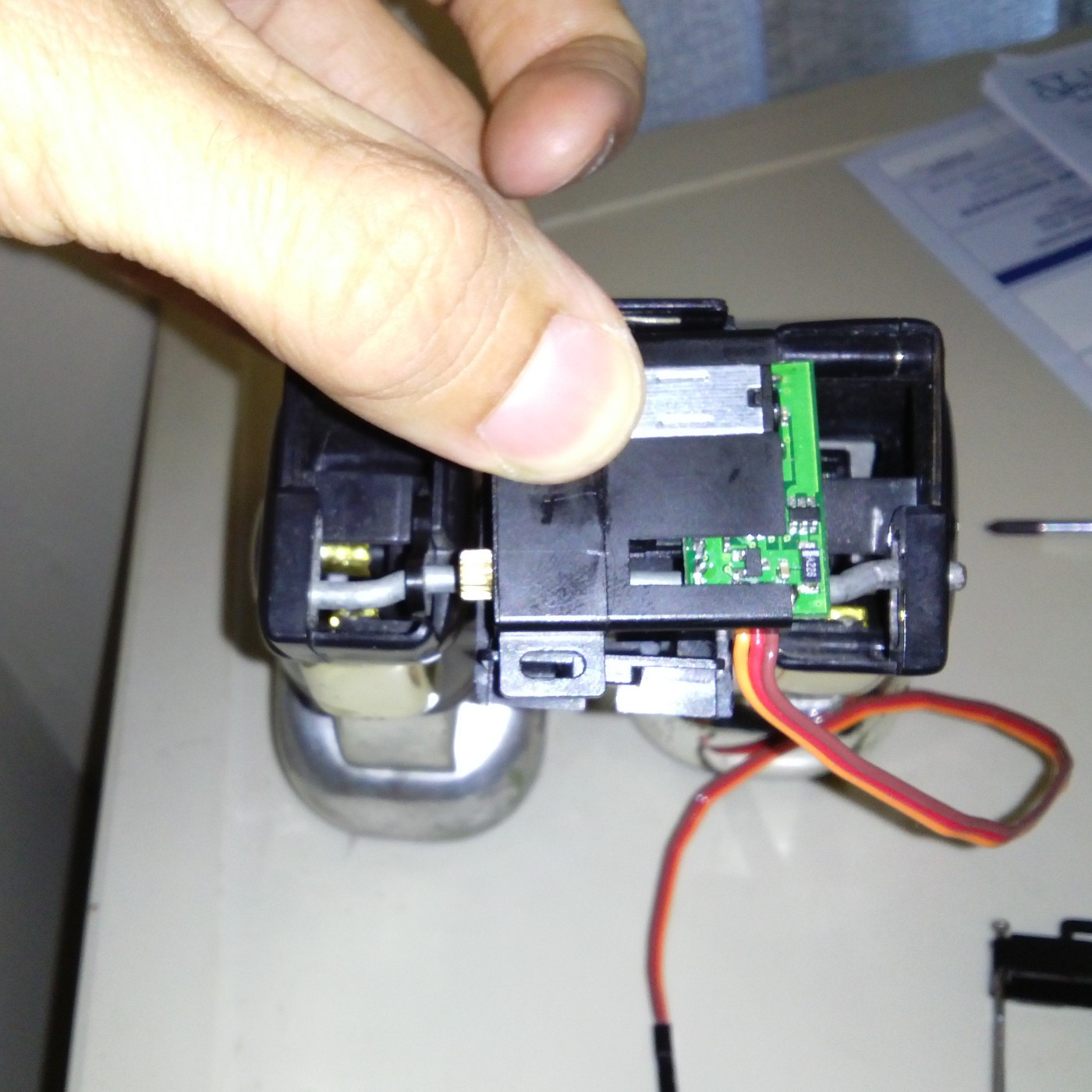
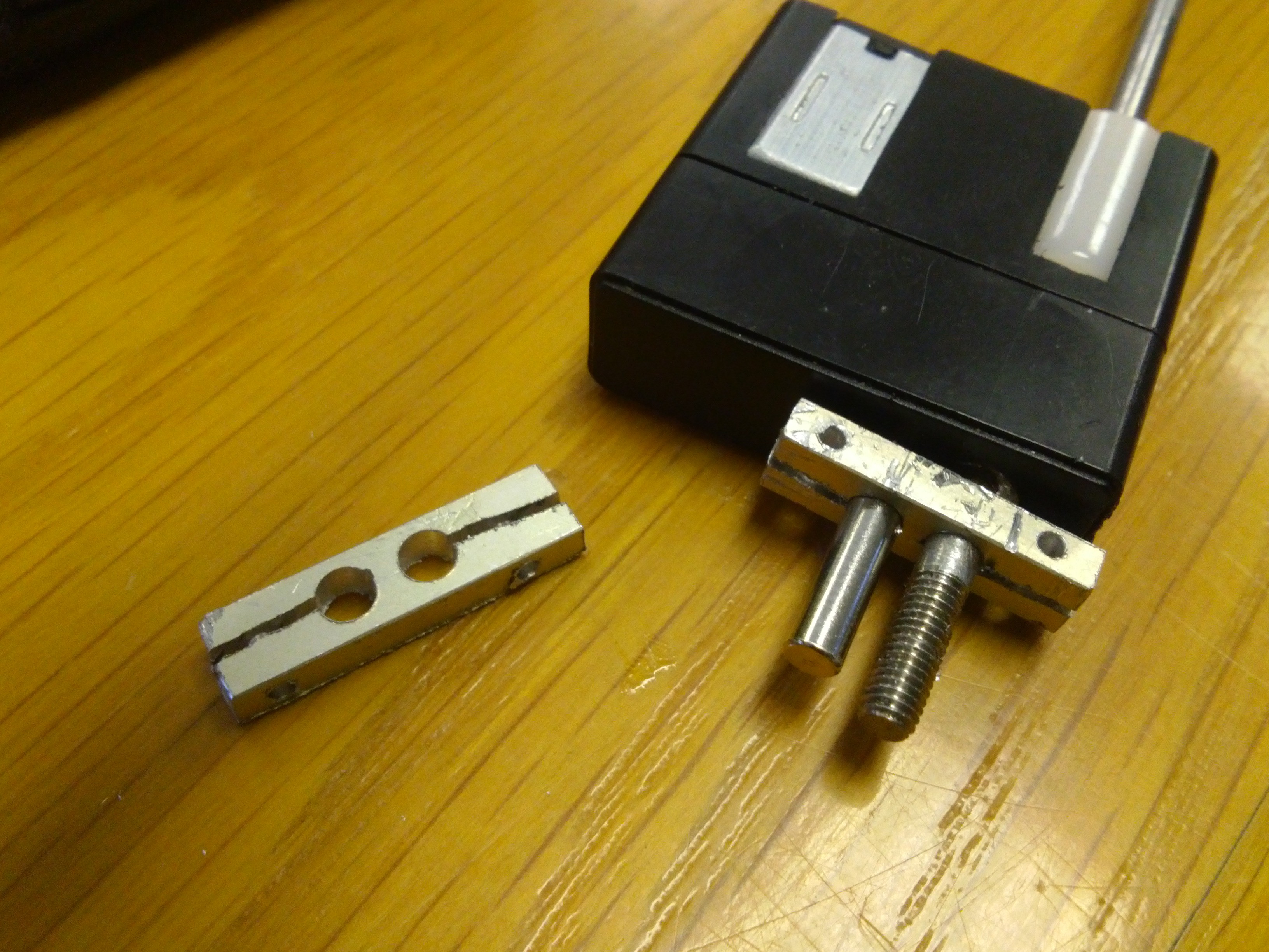
 Once this was all sorted I still had to mount the servo into the plastic pelvis bit. If possible I am trying to prevent the robot looking at all different from the outside, so I couldn't just put a screw right threw it. Instead I drilled through the servo and slightly into the pelvis plastic (to leave an indent that I could use for alignment) and the used a bit of
 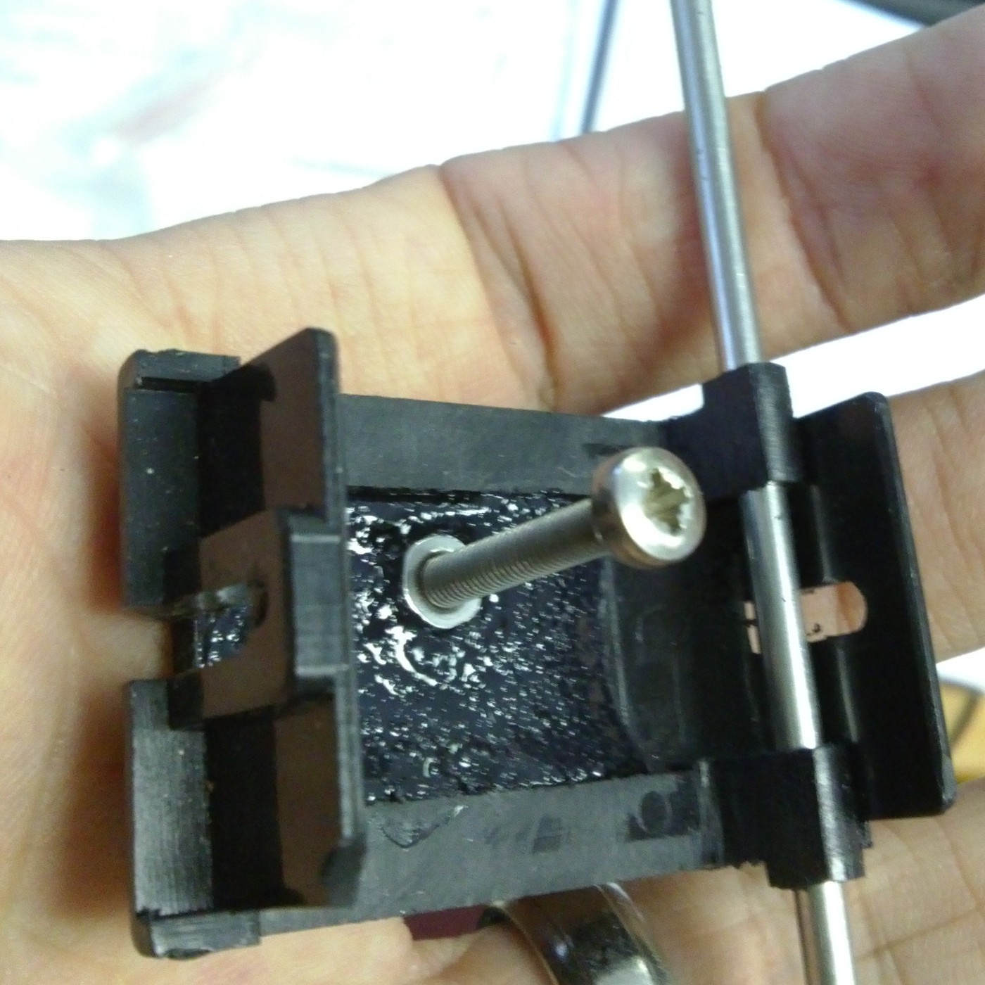 A bit of bent aluminium...
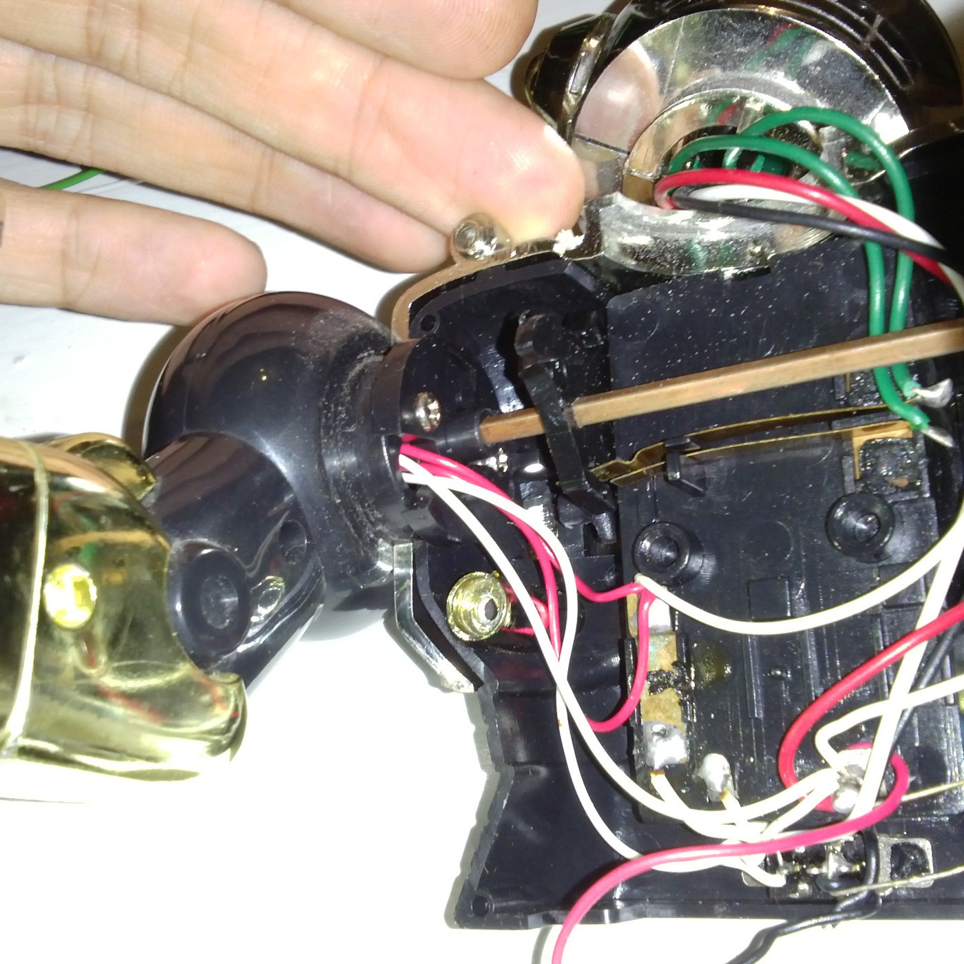


 deʃhipu
 Rue Mohr
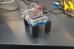
 Scott Clandinin
I grew up in the 60's and after seeing your work, I wish I had kept the robots I had back then :-)