0%
0%
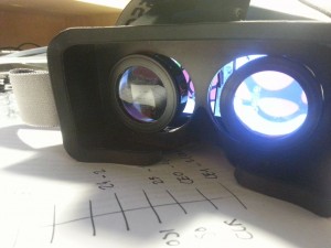
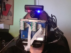
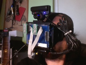
DIY Augmented Reality Device
... with video pass-through ...
 Arcadia Labs
Become a Hackaday.io member
Already have an account? Log in.
Just one more thing
To make the experience fit your profile, pick a username and tell us what interests you.
Pick an awesome username
hackaday.io/
Your profile's URL: hackaday.io/username. Max 25 alphanumeric characters.
Pick a few interests
Projects that share your interests
People that share your interests


 bobricius
 Sasha Shturma
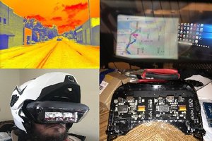
 Josh Starnes
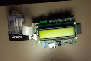
 Brenda Armour
Hey I love your project and hope to make a futuristic motorcycle helmet with IR and FLir style video overlay while riding, as well as fun overlays like weather and stuff. Let me know if your still on here