 jaromir.sukuba
There is not very much magic behind this curve tracer. It works by impulse measurement - so, the voltage (or current) to draw IV curve is not applied step by step by means of adjustable voltage (or current source), but in single impulse from charged capacitor. This allows to have measurement range of ~0,5A and 35V without the need of bulky 18W power source and no DUT cooling needed. Measurement range could be easily increased to few amperes and hudreds of volts, this implementation is just simple case study.
The whole gadget consists of two logical parts - analog and digital; separated on two board. It is not needed to have it separated, but I had those two pieces of scrap perfboard on hand.
Analog board:
There is 35V source made by jelly-bean MC34063 (I didn't even bother to draw complete schematics). This source is permanently on, however separated by reed relay. It can be engaged to charge 22uF capacitor (by transistor on A input). This capacitor could be discharged into serial combination of Rs and DUT by two-transistor switch, engaged by input B. Voltage on DUT is measured on A0 output and combined voltage on A1 output. If Rs is known, current flowing through DUT is given by D*(A1-A0)/Rs, where D is ratio of voltage dividers (in this case - 560k and 39k, giving ratio approx 1/20).
And this is how it looks:

Digital board has to do measurement in three steps:
1, Turn on A, wait for a while to charge 22uF capacitor and turn it off.
2, Turn on B and immediately start sampling both A0 and A1 (both inputs at once) inputs into two long arrays, wait for a while and terminate sampling, turn off B
3, Draw X-Y plot of those two arrays.
(4, ... 5, Profit comes to mind)
To achieve those goals, not that much has to be done
 There is not much more than MCU and display.
It looks like this:

Typical measurement profile on A0 and A1 inputs looks like this
 You can see huge spike on blue line (A1) meaning fast discharge (high current), while voltage on yellow line (A0, voltaeg on DUT) doesn't change that much. This is typical IV characteristics of Zener diode (in this case approx 12V Ur). When drawn in XY mode, it looks like this
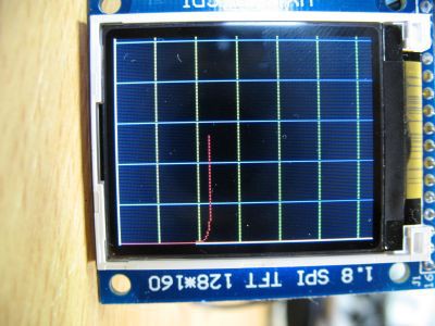 The unmarked axis goes like on would expect - voltage on X (horizontal) and current on Y (vertical). 5V/dev at X and 50mA/div at Y. We can see the same thing - voltage doesn't change very much when going from few mA above, looking quite similar to what could be find in datasheets, like
http://www.vishay.com/docs/85607/bzx85.pdf
Final remarks:
Yes, it works.
Current/voltage range is not that great, but OK for demonstration. Higher resolution display wouldn't harm, to allow more detail and X/Y axis legend. The dsPIC I used is dying from boredom in this application, it is 70MIPS DSP, some lower-end one should be better (it has to have dual sample and hold circuit, or even dual ADC).


 Analog board:


 Yann Guidon / YGDES
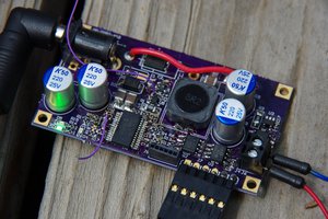
 Jonathan Bruneau
 Paul Andrews
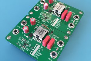
 James Wilson
Nice project.