Build your own Raspberry Pi Weather Station, WeatherPi!
By doing this project you will learn:
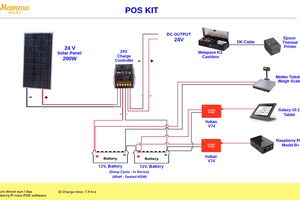
- How to build a solar powered system
- How to design and size the panels and batteries
- How to gather data to analyze your system performance
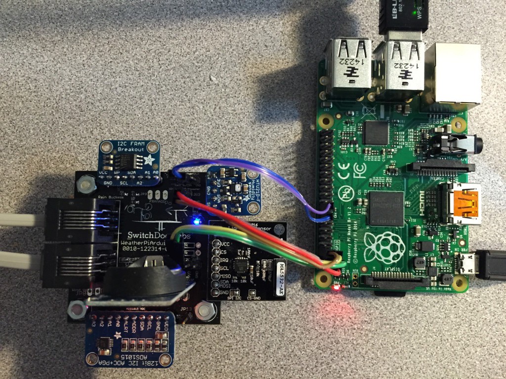
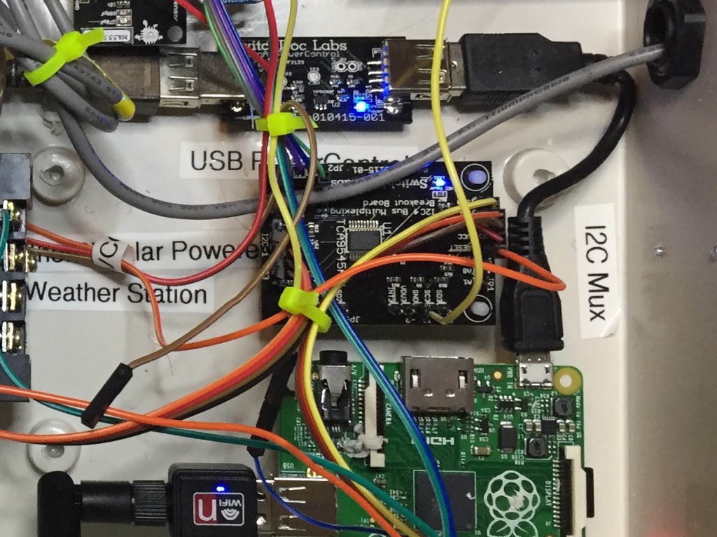
- How to wire up a Raspberry Pi to a solar power system
- How to safely turn a Raspberry Pi on and off
- Building 3D Printed Parts for WeatherPi
And most importantly, have fun doing it!
What is WeatherPi?
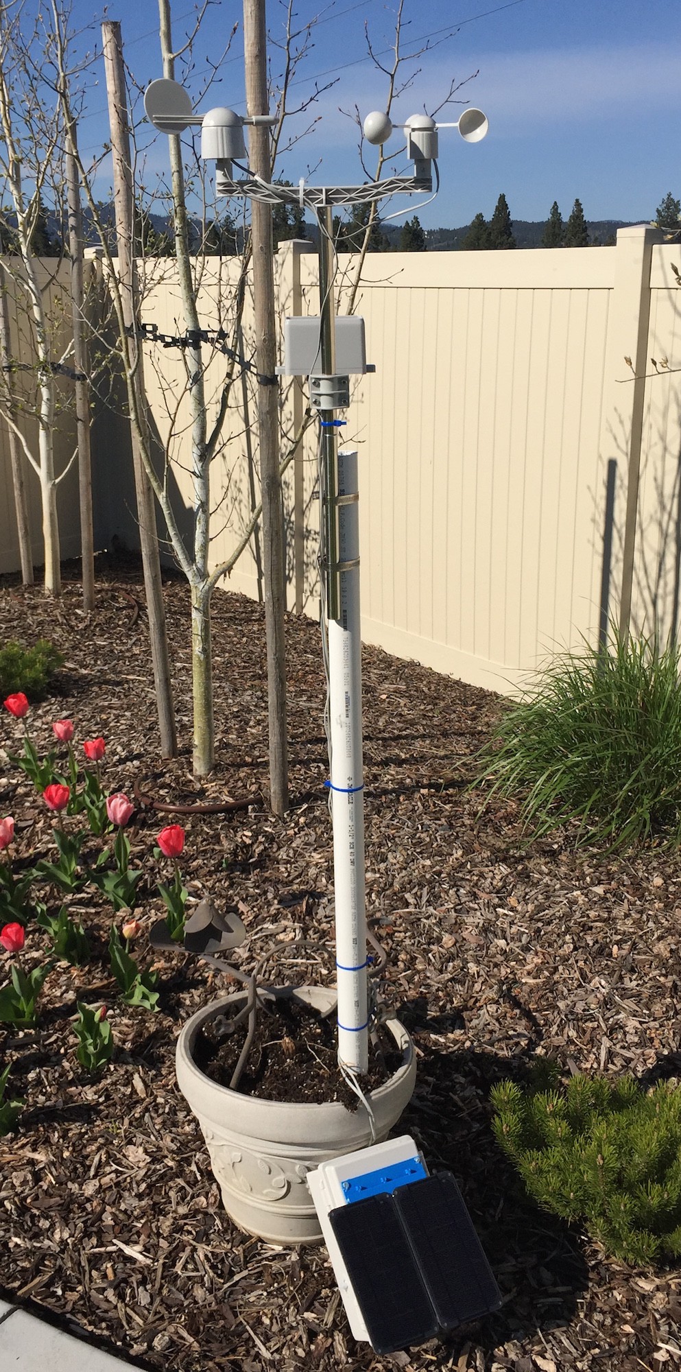
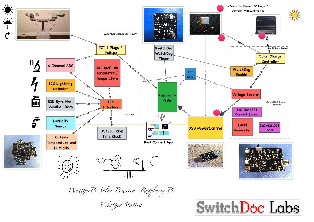
WeatherPi is a solar powered Raspberry Pi WiFi connected weather station designed for Makers by SwitchDoc Labs. This is a great system to build and tinker with. All of it is modifiable and all source code is included. The most important functions are:
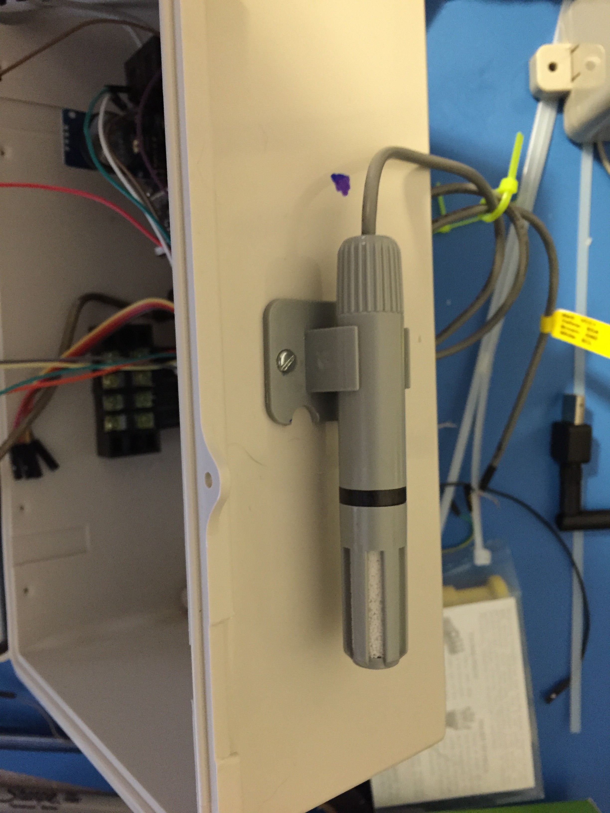
- Senses 20 different environmental values
- Completely Solar Powered
- Has a full database containing history of the environment (MySQL)
- Monitors and reports lots of data on the solar powered system - great for education!
- Self contained and monitored for brownouts and power issues
- Can be modified remotely
- Download your data to crunch it on your PC
- Can be modified to do SMS (Text) messaging, Twitters, webpages and more
- Has an iPad Based Control Panel
- Easy to connect to Twitter, WeatherUnderground, etc
This project will show you how to build a WiFi Solar Powered Raspberry Pi Weather Station. This project grew out of a number of other projects, including the massive Project Curacao, a solar powered environmental monitoring system deployed on the Caribbean tropical island of Curacao. Project Curacao was written up in an extensive set of articles in MagPi magazine (starting in Issue 18 and continuing through Issue 22).
The WeatherPi Solar Powered Weather Station is an excellent education project. There are many aspects of this project that can be looked at and analyzed for educational purposes:
- How do solar power systems behave? Limitations and advantages
- Temperature, Wind and Humidity data analysis.
- Shutting down and starting up small computers on solar power
- Add your own sensors for UV, dust and pollen count and light color
Follow along on updates to the WeatherPi story on www.switchdoc.com.

 dave
dave
 Tom
Tom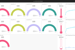
 Initial State
 4D Makers
Nice work! You should add camera there too ;)