 Jithin
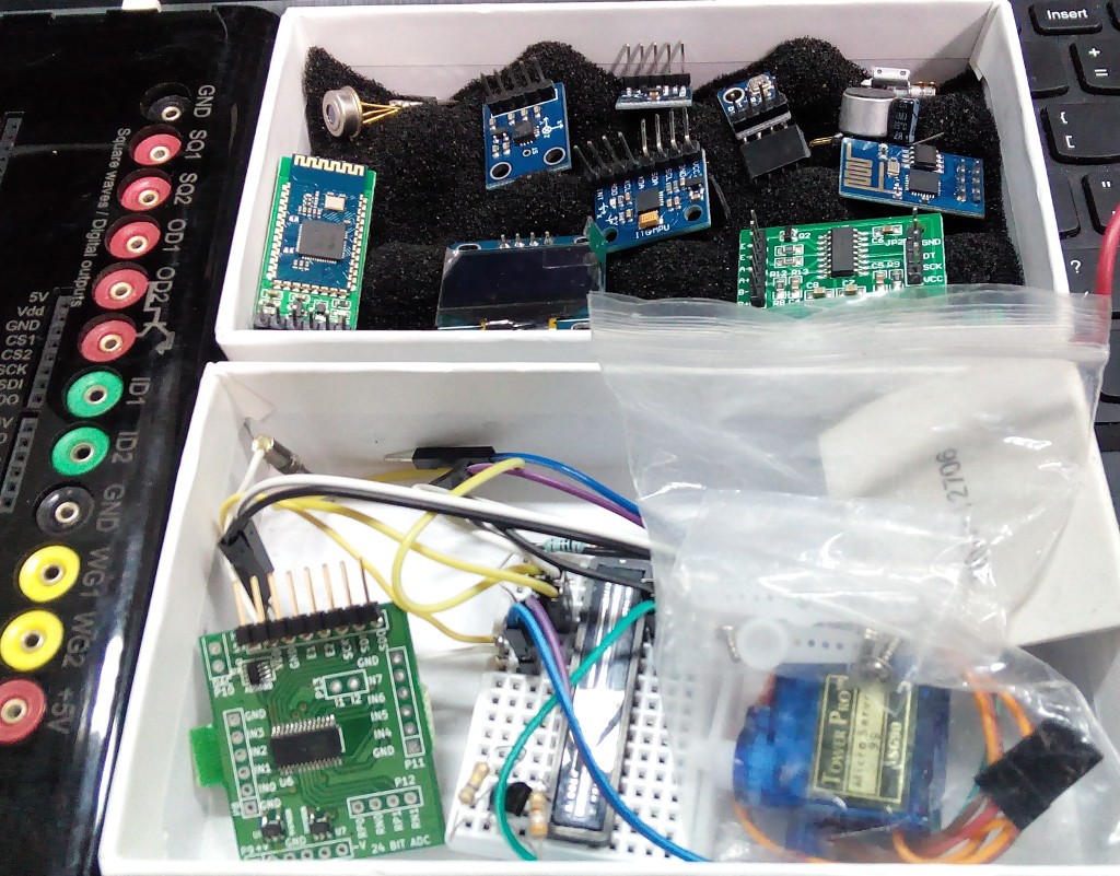
Thanks to the vibrant hobbyist market, several sensors which would otherwise have remained inaccessible owing to their reflow-only footprints, are now available in amateur friendly breakout boards with clearly labeled pins.
I bought up a bunch of these, and tested most of them. Several of these use SPI/I2C, and companion classes to support them can be coded on the PC side without having to touch the firmware. Some however, use non-standard/timing critical protocols, so I have added support for them in the firmware. These include ( I may have mentioned them in a previous log somewwhere ), the HX711 weighing sensor(24-bit fully differential, 128x PGA), DHT22(humidity), and a 3648 element optical array from Toshiba.
Here's an example of what a Python side class for a sensor may look like.
#HMC5883L 3-axis magnetometer
import Labtools.interface as interface
import time
from numpy import int16

class HMC5883L:
	def __init__(self,ADDRESS=0x1E):
		self.ADDRESS = ADDRESS
		self.I = interface.Interface()

	def connect(self):
		self.I.I2C.start(self.ADDRESS,0) #writing mode
		self.I.I2C.send(0x01) #gain
		self.I.I2C.send(0<<5) #smallest range
		self.I.I2C.stop()


		self.I.I2C.start(self.ADDRESS,0) #writing mode
		self.I.I2C.send(0x02) #Mode
		self.I.I2C.send(0)    #Continuous measurement
		self.I.I2C.stop()

	def __getVals__(self,addr,bytes):
		self.I.I2C.start(self.ADDRESS,0)
		self.I.I2C.send(addr) #read raw values starting from address
		self.I.I2C.restart(self.ADDRESS,1)
		vals=self.I.I2C.read(bytes)
		self.I.I2C.stop()
		return vals

	def read(self):
		vals=self.__getVals__(0x03,6)
		x=int16((vals[0]<<8)|vals[1])	#conversion to signed datatype
		y=int16((vals[2]<<8)|vals[3])
		z=int16((vals[4]<<8)|vals[5])
		return x,y,z


'''
a=HMC5883L()
a.connect()
while 1:
	print a.read()
'''
The above code ignores error codes returned by the I2C functions, and needs much work.
refer to http://pythonhosted.org/LabtoolSuite/interface.html for a rough programmer's manual generated using Sphinx.
A UART relay has been implemented, but it's fairly buggy at this point. When activated, all data sent to the device is ignored, and relayed directly to the output port, and vice versa. It can be used to test UART devices like bluetooth modems with little overhead.
There are two modes. One where the device returns to normal functionality if no data is exchanged for more than one second, and another where a power cycle is required for the device to return to normal functioning. Can possibly be used for programming secondary microcontrollers with bootloaders such as the ESP8266.
Here's some example output from a BOLUTEK bluetooth modem(left side of the box in the picture above), after I activated the relay.
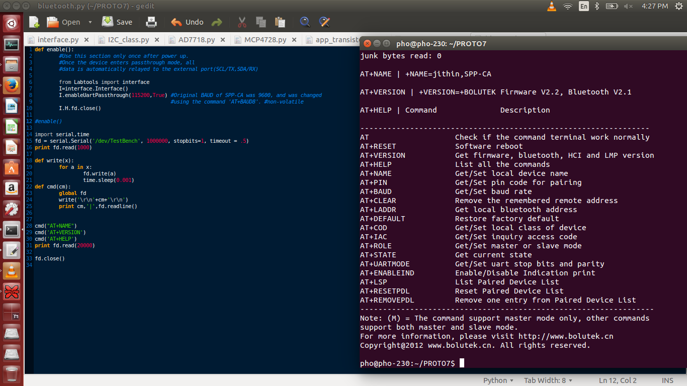
The 1ms delay between characters is to prevent buffer overflows caused by the much lower BAUD rate of the modem. I could alter the vLabtool's BAUD rate to keep up, but like I said, there are many problems with this feature that need to be looked at.
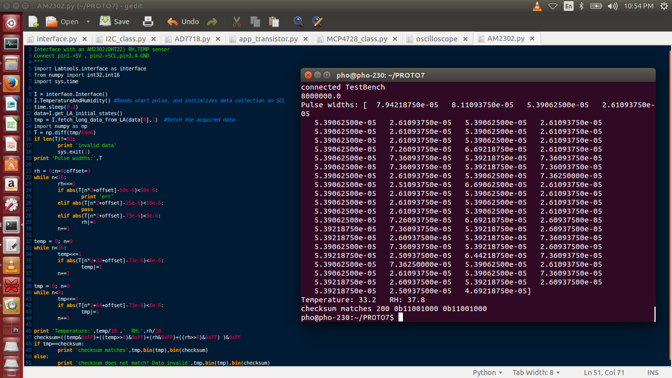
Here's an elaborate explanation on how the DHT-22 sends data, along with the timing details for all the pulses. I will soon write a dedicated loop in the firmware which collects and sorts the pulse width encoded data in real time, but using the logic analyzer first gave me an accurate idea of what the timing details are.
The code is self explanatory.
Currently testing a PIC16F1618+NRF24L01+ combo for making wireless sensor nodes.
Discussions
Become a Hackaday.io Member
Create an account to leave a comment. Already have an account? Log In.
Hey, this log is severely outdated. Most of the I2C, SPI calls have been moved into firmware, and you can fetch and write data with single commands. Even acquire data in precise intervals(1uS apart) I need to update a lot of these.
HX711 has a weird protocol. Barely made it work, and quickly moved to AD7718 and a couple of other 24-bit options.
Haven't got readable code, but you basically have to push 24 pulses into the HX711 and read the output after each pulse goes high. Keep shifting the read bits into a 24 bit register.
Once you're done with the 24 bits, a fixed number of additional pulses are used to set the mode of the HX711
1 extra pulse : CHANNEL A is selected with 128x gain;
2 extra : Channel B selected with 32x gain
3 extra : Channel A selected with 64x Gain
So basically, You have to read one datapoint in order to change the mode for the next one!
Set the pulse output permanently high to turn off the module. Keep it low to let it run.
Are you sure? yes | no
Thank you so much for the article!
Could you successfully with using the above framework to utilize HX711?
If yes, would you mind sharing the codes with us? :)
Are you sure? yes | no