Close
0%
0%

Modular Continuous Track System

A inexpensive modular tank track system that can be used for robotic and radio controlled vehicles.

Similar projects worth following
Description
This is a modular continuous track system for small to large robotics and radio controlled vehicles. I was disappointed with the availability and design of currently marketed designs. There seems to be several options for very small projects and a few options for large vehicles. But no options in between. Additionally, I noticed a few common design issues which I hoped to address with my design.

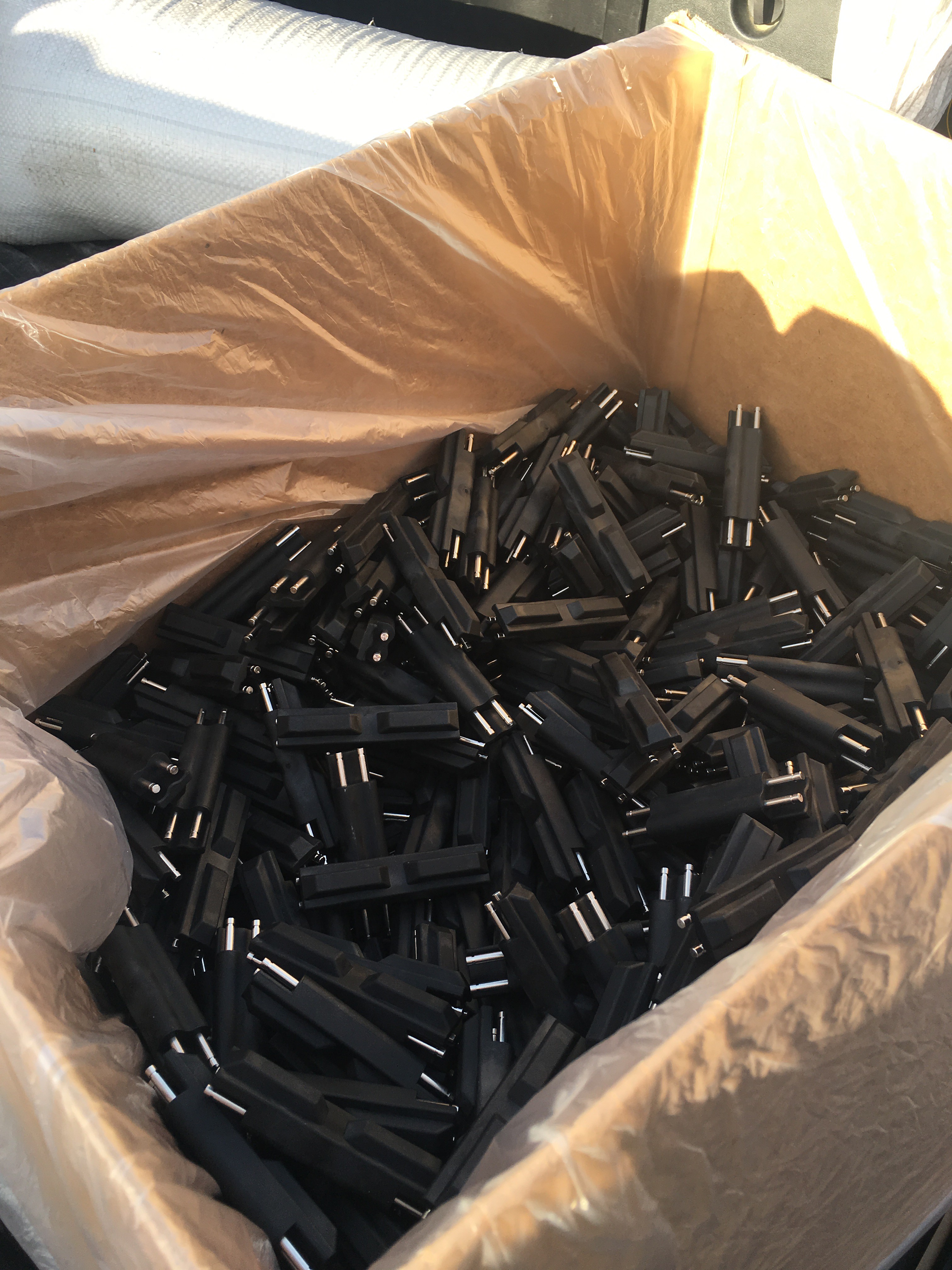
We are actively manufacturing and selling track. If you are interested feel free to contact me or visit our website.

www.tankchain.com

We also partnered with a roller chain company to be able to provide sprockets to complement our track. In the future we are hoping to offer keyed shafts, and shaft collars as well. We can provide you with a complete kit now.

We are also working on some robot kits. Please inquire about that as well.

  • 1 × Urethane Rubber This is a two part resin that cures to form a shore 70A rubber
  • 1 × Custom Pins I had custom pins designed to match standard roller chain
  • 1 × Roller Chain Components
  • 1 × Custom Machined Aluminum Mold
  • 1 × Air Powered Syringe

  • Gas Permeability of vinyl tube; and why it sucks.

    jupdyke09/06/2016 at 21:11 0 comments

    It has been a little while since I really posted anything other than a brief update. I really have not had anything interesting to publish or share. I moved my setup to my basement, this required first cleaning up the basement, building a workbench, moving everything, running new outlet wires, adding lights and getting a dehumidifier. It was a lot of work, but worth it to have a dedicated space.

    I have not been running the resin molding system too much lately. This is mostly because I got parts injection molded and have several thousand black Tank Chain treads. :) Since the vast majority of my orders are black track, I no longer mold those using my resin system. I only make the custom colors now.

    This means that the resin system has been sitting for quite a while. One issue with the resin I am using is the shelf life once opened. The Part A resin will harden without being mixed with Part B. And I have noticed that Part B will turn almost black. This completely ruins it for making custom colors because once it is black it is nearly impossible to get any other color.

    I have been storing my resin in my custom dispenser using Corny Kegs and they work GREAT! I knew the resin would harden if left open and didn't want it to harden inside the kegs. So I added some R134a to the kegs as a dry gas blanket. This worked great, and even after a month in the keg the resin was still liquid. But I noticed the Part A in the clear vinyl tubes coming from my keg was solid, and the Part B was black. This was never an issue when I was making a lot of parts becuase I was running the resin through the tube every day or two.

    Lucky for me I had enough spare tube to cut it off and replace it. This was annoying but only took 1-2 hours to get everything back into working order. But it made me think, why was the resin hardening in the tubes?

    Well I am not 100% sure yet, but I have a good guess. After talking with my buddy who brews beer, he mentioned that the vinyl tube has some gas permeability. Meaning that gas leaks through the tube. Normally this is not much of a problem. The amount that leaks out is a small percentage. But if you are storing CO2 kegs under pressure with 20 feet of vinyl tubing, the percentage might be enough to care about.

    For my application it is the opposite problem. The air can be getting through the vinyl tube and causing the resin to harden. It doesnt happen fast, but after 2 weeks I now have a clogged up dispenser.

    Here is a good link which gives some approximate numbers for how much gas can leak from various types of tubes.

    http://partners.coleparmer.com/techinfo/techinfo.asp?openlist=D,E,C&htmlfile=SelectingTubing.htm&Title=Search

    If you look at the bottom you can see that vinyl tube has a value of 360 for C02, 40 for O2, and 80 for N2. The units are a little confusing at first {cc-mmsec-cm2-cm Hg } x 10-10, but basically you need to know the pressure the tube is under and the surface area. I don't need to calculate the value, but I can use these values to select a better type of tubing.

    I am not 100% sure that this is the problem, but it definitely makes sense. Being exposed to humid air definitely causes the resin to harden. This is why having the R134A dry gas blanket in the kegs is so important. Another idea I had was UV light exposure could be hardening the resin. Simple solution to both is to order some opaque tube which is not air permeable.

    I will report back my results when I get them.

    Josh

  • Update after a long break

    jupdyke08/30/2016 at 20:23 0 comments

    I just wanted to give an update. It has been a while since I posted and that is mostly due to nothing particularly hackaday worthy. I have been focusing mostly on fulfilling orders and shipping out parts. That has stalled some of my r&d efforts, but I am very happy to be sending the product out to customers. It has taken a while, but I am now starting to get some pictures back from them of their robots. Hopefully that continues and I can show off more and more tracked robots.

    I also moved my workspace to a new area and have been slowly setting that up. The method I am using works pretty well. The aluminum molds and heated plates continue to crank out parts time after time. I am curious what the life of the molds will be, but so far am not seeing any change in part quality. The edges of the mold are getting a little banged up from prying them open. But that was expected. In the future a mold opener might be nice to have. Something that pulls the mold open evenly rather than prying it.

    Since the method is working well there has not been much hacker worthy notes. When I was first starting this project I was having to make a lot of tools, develop new methods and stuff like that. But now that the system is running smooth I just sit down and start making parts. I have several thousand black parts injection molded already and I only custom make the colored parts now. So I that has reduced the number of parts I am making by hand too.

    One area that is interesting is prolonging the life of the resin. But I will post on that in a seperate log. Thank you to all the support.

  • New Advertising Video

    jupdyke05/12/2016 at 19:48 0 comments

  • Unboxing Video

    jupdyke02/10/2016 at 05:21 2 comments

    I have been making steady progress and have shipped out almost all the current orders. I was waiting on the injection molded parts to arrive and then it was a mad rush to repackage and ship parts as soon as possible.

    One of the First Robotics teams asked if I could sponsor them. While we are not really big enough to do so in the traditional sense, I did have several prototype parts I had made that I sent them. They were excited and did an unboxing video. it is really cool to see someone do an unboxing video of a product I designed. lol


  • New Smaller Track

    jupdyke02/04/2016 at 04:54 4 comments

    This project has been growing so fast it is hard to post about all the parts. One of my customers asked if I could do a smaller size track and I got another size of pins made and a new mold. I did a few things differently on this mold as I have learned a lot over the past year of working on this project. I am trying to step up my injection mold design to get closer to how a commercial mold would be made.

    I now have a runner which allows me to fill two cavities through a single hole. I would like to get to the point where I am filling the whole mold from a single inlet. But I was not sure how that would work. So I compromised and did only two parts per inlet. This way if it failed, I could always drill more inlets. I also reduced the size of the air vent. Now the vents are much smaller than the inlet which should help in the situation where one cavity fills before the other. Air can escape much easier than the resin so if one cavity fills first, the other should fill easier and equal out.

    All in all, this experiment worked perfectly and now I can offer a second size product. Below are some photos. You can see some aluminum powder in the parts because this was the first time the mold was shot.

  • Hundreds of Tank Tracks

    jupdyke02/03/2016 at 21:19 0 comments

    Here is a picture of the first box of about 500 parts. Probably not as exciting to others as it is to me. I should end up with about 15 boxes likes this. Two of which should arrive tomorrow.

  • Just left the injection molder

    jupdyke02/01/2016 at 19:11 0 comments

    I just left the injection molder and the parts look amazing. The fit is great and the rubber is just as grippy as the ones I was making. Seeing their equipment really makes me want an injection molding machine of my very own. Maybe one day.

  • Injection Molding Big and Small

    jupdyke01/30/2016 at 21:12 0 comments

    It has been another busy week. All the orders have shipped out using the parts we made in house. The past month has been very informative about what processes work, what dont, and what just take too long or are too hard. I always knew that filling the molds by hand would be too much work in the long run. But I also did not want to just straight to injection molding. I needed to gauge my market, and get a lot more parts in hand to test with.

    Over the past year my production rate has gone up dramatically. Here is a little breakdown:

    • Initial 2 cavity silicone mold - 2 parts every 4 hours. (2 hours / part)
    • Second 5 cavity silicone mold - 5 parts every 4 hours. ( 48 minutes / part)
    • Addition of heat to silicone mold - 5 parts every hour. (12 minutes / part)
    • Aluminum mold (12 minutes / part)
    • 3 Aluminum molds (4 minutes / part )

    No too shabby if I do say so myself. But I have reached the point where more aluminum molds will not speed things up any more and it is still tough work to get 15 parts per hour. So as I have mentioned already I am going to an injection molding company to get 7500 parts made in black. But this is not cheap and I am betting a big chunk of money that I can sell all those parts to break even. I like my odds.

    So if I can go to injection molding why would I care about increasing my internal capability for making parts. Well I have several reasons. The first is that with outsourcing the injection molding I will only ever be able to make 1 color and one size cost efficiently. Changing colors has fees and different sizes requires a new mold. So I want to be able to do custom colors and custom sizes.

    The second reason is for R&D purposes. I have ideas to expand my system to other sizes and shapes. That means I will need to be able to prototype those parts cheaply and easily.

    The final reasons is that injection molding is not cheap. If I can make the parts myself I can keep more of the profits.

    So that brings me to the conclusion that I need my own injection molding machine. I could buy a cheap one, or I could save up and buy a nicer one. But this is Hackaday. We build stuff here. So I started toying around with some ideas about building my own micro injection molding machine. It is not that crazy actually. There are quite a few point who have done this, and hackaday has featured a few. Time for me to throw my hat in the ring too.

    Ever since I started this project I have been trolling the internet and found a few cool builds or products. Now I started designing my own machine. Over the years I have learned a few things about my projects. The first is that I start way too many, hardly finish them, and they always take longer than I expect. So the way I deal with this is to try and make projects scaleable. What is the minimum amount of work that gets to me to a useful product, and then how can that be improved over time. This way I get something useful earlier, and depending on how useful it is I can upgrade it.

    With the injection molding machine the first useful step is just being able to open and close the molds. Right now opening the mold is actually a pain in the butt. Here is a picture of the design so far and a link to yet another hackaday.io project page.

    Micro Injection Molding Machine

  • Injection Molding Big and Small

    jupdyke01/30/2016 at 21:10 0 comments

    It has been another busy week. All the orders have shipped out using the parts we made in house. The past month has been very informative about what processes work, what dont, and what just take too long or are too hard. I always knew that filling the molds by hand would be too much work in the long run. But I also did not want to just straight to injection molding. I needed to gauge my market, and get a lot more parts in hand to test with.

    Over the past year my production rate has gone up dramatically. Here is a little breakdown:

    • Initial 2 cavity silicone mold - 2 parts every 4 hours. (2 hours / part)
    • Second 5 cavity silicone mold - 5 parts every 4 hours. ( 48 minutes / part)
    • Addition of heat to silicone mold - 5 parts every hour. (12 minutes / part)
    • Aluminum mold (12 minutes / part)
    • 3 Aluminum molds (4 minutes / part )

    No too shabby if I do say so myself. But I have reached the point where more aluminum molds will not speed things up any more and it is still tough work to get 15 parts per hour. So as I have mentioned already I am going to an injection molding company to get 7500 parts made in black. But this is not cheap and I am betting a big chunk of money that I can sell all those parts to break even. I like my odds.

    So if I can go to injection molding why would I care about increasing my internal capability for making parts. Well I have several reasons. The first is that with outsourcing the injection molding I will only ever be able to make 1 color and one size cost efficiently. Changing colors has fees and different sizes requires a new mold. So I want to be able to do custom colors and custom sizes.

    The second reason is for R&D purposes. I have ideas to expand my system to other sizes and shapes. That means I will need to be able to prototype those parts cheaply and easily.

    The final reasons is that injection molding is not cheap. If I can make the parts myself I can keep more of the profits.

    So that brings me to the conclusion that I need my own injection molding machine. I could buy a cheap one, or I could save up and buy a nicer one. But this is Hackaday. We build stuff here. So I started toying around with some ideas about building my own micro injection molding machine. It is not that crazy actually. There are quite a few point who have done this, and hackaday has featured a few. Time for me to throw my hat in the ring too.

    Ever since I started this project I have been trolling the internet and found a few cool builds or products. Now I started designing my own machine. Over the years I have learned a few things about my projects. The first is that I start way too many, hardly finish them, and they always take longer than I expect. So the way I deal with this is to try and make projects scaleable. What is the minimum amount of work that gets to me to a useful product, and then how can that be improved over time. This way I get something useful earlier, and depending on how useful it is I can upgrade it.

    With the injection molding machine the first useful step is just being able to open and close the molds. Right now opening the mold is actually a pain in the butt. Here is a picture of the design so far and a link to yet another hackaday.io project page.


  • Another Video

    jupdyke01/22/2016 at 00:20 0 comments

    Hello all,

    We have been selling tracks for about two months we are starting to have customers that have been able to put the track to use. Below is another awesome video of the tracks in action.

View all 49 project logs

Enjoy this project?

Share

Discussions

notmove wrote 02/07/2022 at 18:51 point

This is amazing, I like your track program to run the automotive machine. can You share the program file? I want to test for jrs track and trace module.

  Are you sure? yes | no

tormenized wrote 12/17/2019 at 11:52 point

Do u have a 1/6 scale rubber tracks for tiger 1 tank? 

  Are you sure? yes | no

ActualDragon wrote 10/18/2016 at 16:05 point

what did you do the cover photo with?

  Are you sure? yes | no

jupdyke wrote 10/18/2016 at 17:13 point

I used SoildWorks to make the 3d models and just saved a jpeg from there. I wish I had more time to actually build the robots with these tracks, but keeping up with orders seems to take up most my free time.

  Are you sure? yes | no

ActualDragon wrote 10/18/2016 at 17:44 point

thanks

  Are you sure? yes | no

Neon22 wrote 10/24/2015 at 08:16 point

The good news is you've made the right choice :).

It appears there is an ISO standard metric (British Stanbdard Chain) and the ANSI standard (US inches).

Here's some potentially useful conversion links and charts:

Ansi sizes in inches and mm http://www.ocm.co.jp/en/han_info/05_01.pdf

An online calculator: http://www.sprocketsunlimited.com/Chainspecifications.html

Good overview and ones that do and do-not match http://www.globalspec.com/learnmore/mechanical_components/chains_sprockets/sprockets_roller_chain_metric

Alas it appears that although the chain may be similar, the ISO and ANSI sprockets are not interchangeable :( The good news is that the ISO standard is losing out in the market to the ANSI standard. To quote:

"ISO standard R606 dictates sprocket uniformity for most European and
African nations. This standard is in relation to British Standard Chain,
which is dimensionally different than chains meant for ANSI sprockets.
ISO sprockets have large pitches that are measured in sixteenths of an
inch, but are expressed in metric units. British Standard Chain was
developed before American-styled chain, but was limited in its
development by what materials were readily available as roller chains
evolved. The outer plates of an ISO chain are taken from the chain size
one level above the application requirements. This led to bulkier,
heavier chain with a longer fatigue life that is still used today."

  Are you sure? yes | no

Neon22 wrote 10/24/2015 at 04:22 point

What are dimensions in metric. I think only the USA is still using inches.

  Are you sure? yes | no

jupdyke wrote 10/24/2015 at 05:51 point

You are correct that the USA is about the only place using inches. But I also live in the USA. I designed it around ANSI roller chain which is quite common and since that is designed in inches, so is my track. This size is 7.62 cm wide and matches with size 35 roller chain. I designed it around this because it is very common. I dont know too much about European roller chain, but 35 chain has a 0.375 inch pitch, which is 9.5mm. I intend to offer other size track to match with other size roller chain. From what I understand ISO roller chain is still designed in 1/16th of an inch. So my design should match with ISO 06B-1  roller chain sprockets. I would love to test this out or talk with some people that know more about roller chain in Europe.

  Are you sure? yes | no

James Newton wrote 09/14/2015 at 20:16 point

Love the mold making! For indoor tracked robots, this looks perfect... I'll be curious to see what price you can sell them for. 

  Are you sure? yes | no

Jarrett wrote 07/13/2015 at 15:28 point

I don't have any expertise on this, but my gut reaction is that it's not really a great idea to be putting weight on the drive sprockets. They're typically really light and flimsy and designed to be torsionally strong, not compressionally. Some of those hobbyist drives you've posted look like they do that, but you can see from the military stuff that it's not done.

  Are you sure? yes | no

jupdyke wrote 07/13/2015 at 15:36 point

Jarrett,

I agree that the sprockets are not designed for this situation. That being said I think many small hobby project would be fine using them this way. For heavier projects you should have bogie wheels that run on the track. I have always thought that you could use smaller sprocket for bogie wheels, but I also designed the track to allow a regular wheel to be used. In fact I even have some design work for a horn, which is the part that keeps the track on a normal bogie wheel. 

Great comment though. I should do some simple simulation to see how much loading you can put on sprockets. It would be interesting to know.

Josh

  Are you sure? yes | no

exuvo wrote 07/13/2015 at 11:23 point

More info about my track designs follows as requested.

My first attempt at robotics used a cheap bought chassis which was truly awful outdoors. It got a whole 10cm until it got stuck in snow. http://exuvo.se/pic/image/KBot V1/20111023_004.jpg

For the second version I bough normal roller chains and used my newly aquired 3D printer to make track sections that attached to the 1mm edge on the chain links. This was a dual chain setup using hard PLA plastic. http://exuvo.se/pic/gallery/KBot V2 Video of it driving around indoors https://www.youtube.com/user/exuvoo/videos.

In version three I decided to only use a single chain mostly due to weight but also that roller chains are really sturdy and does not need the extra support from two chains. http://exuvo.se/pic/gallery/KBot V3 Unfortunantely I never built it up to the point of being able to drive around.

I almost forgot I had a minor problem with the link design when going over hard flat surfaces.


If you look closely at the rear plastic link that is touching the rearmost suspension wheel  you can see that with flat links you get a bump each time it turns. Of course this only happens with stiff plastic and the best solution is probably to use rubbery materials. Another solution I was thinking of trying is having rounded links. The bump disappears but now has much less touching ground surface and worse weight distribution.

Version four which I'm currently working on is going to use the same tracks as version three but I might change the suspension as I now have a much larger 3D printer and don't need to split things just to be able to print it. I have also bought flexible filament which I'll use for the ground touching part of the plastic links (dual printheads on my printer so I can mix materials on the fly). Short write up about why version four exists http://exuvo.se/project/page/kbot4. Pictures of CAD model as of writing http://exuvo.se/pic/gallery/KBot V4.

  Are you sure? yes | no

exuvo wrote 07/10/2015 at 11:22 point

I have also been trying to build tracks for the last years and I think you have overlooked something. Pictures of my previous version: 

 
When I tested mine in snow the tracks got stuck because snow built up inside the chains where the teeth go but due to the other end being blocked it failed. My new version has a hole on the other side so that the tooth can push snow out. 

A real world example: 
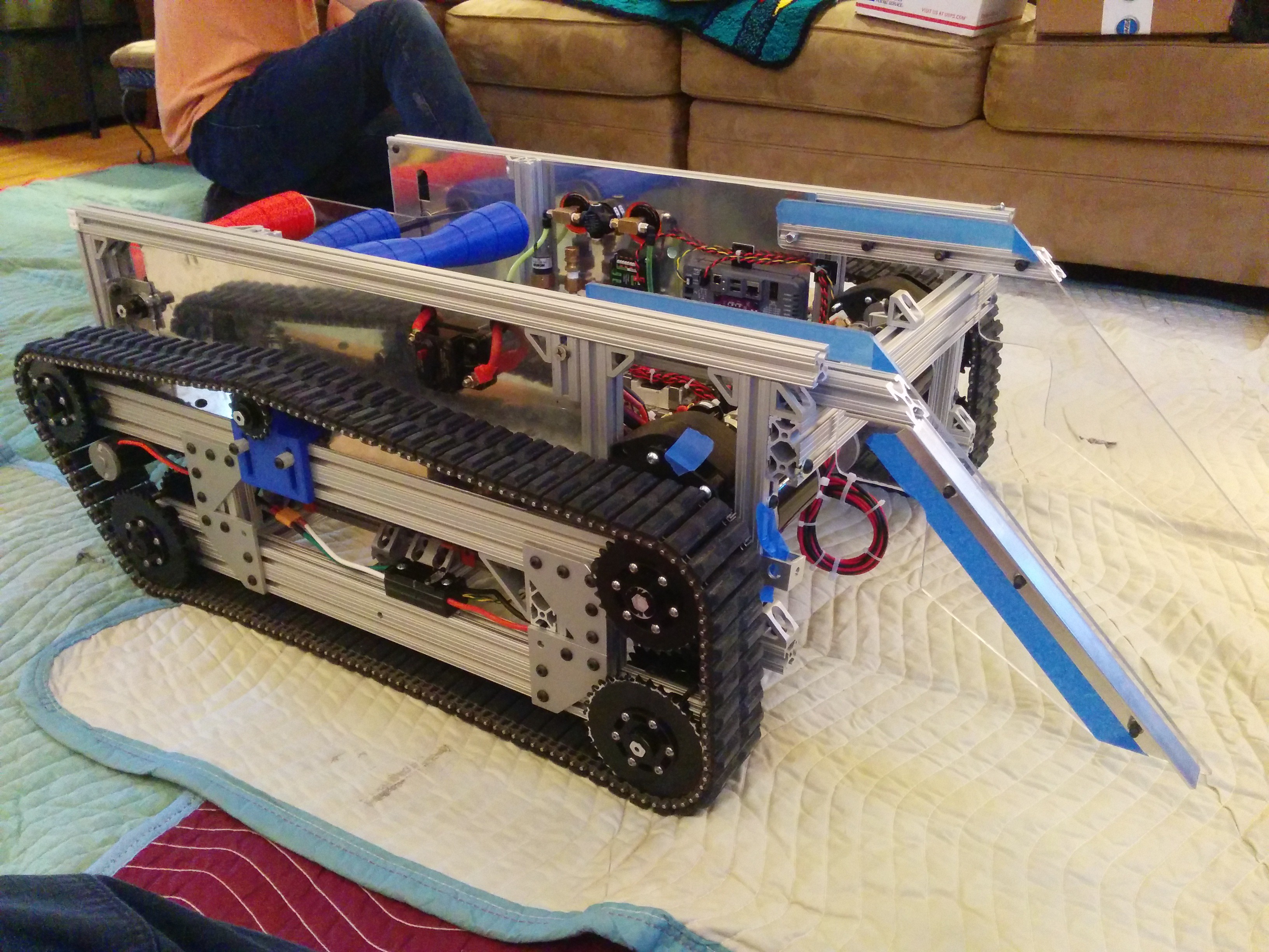
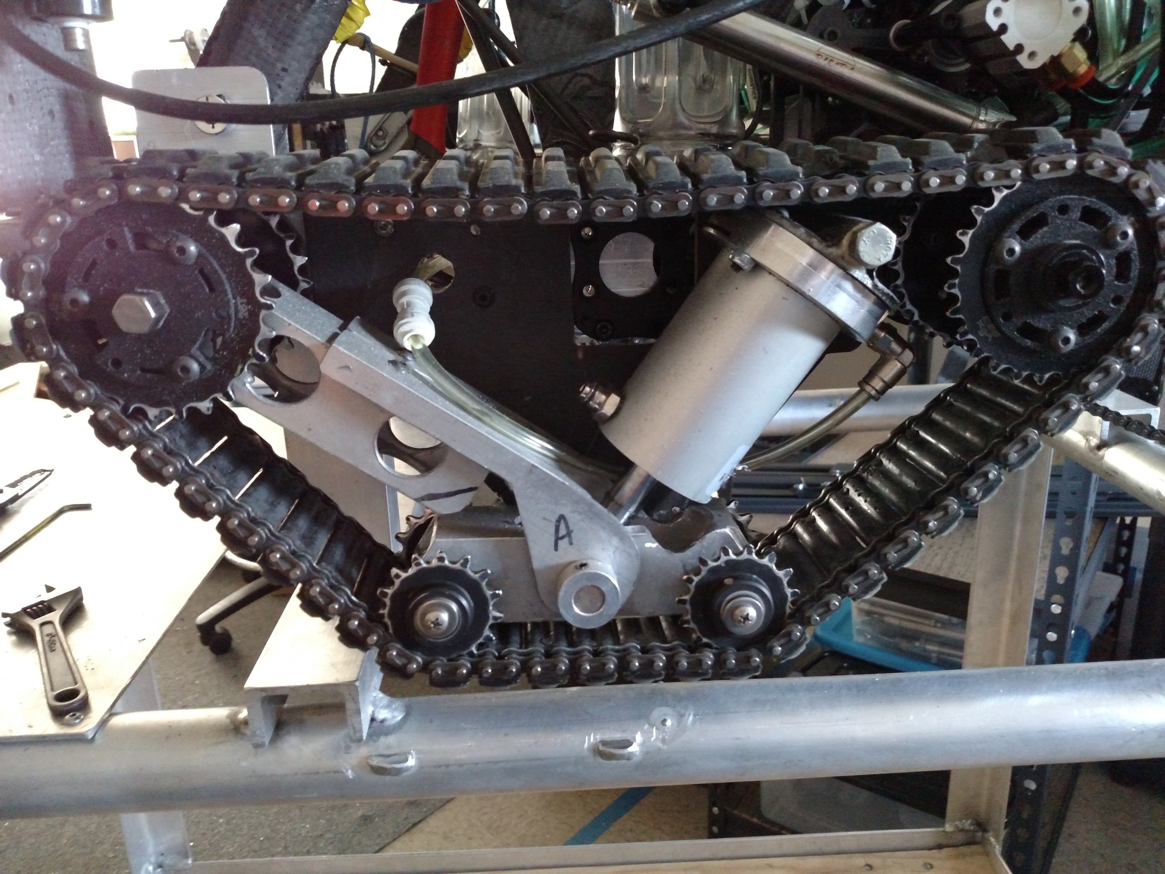
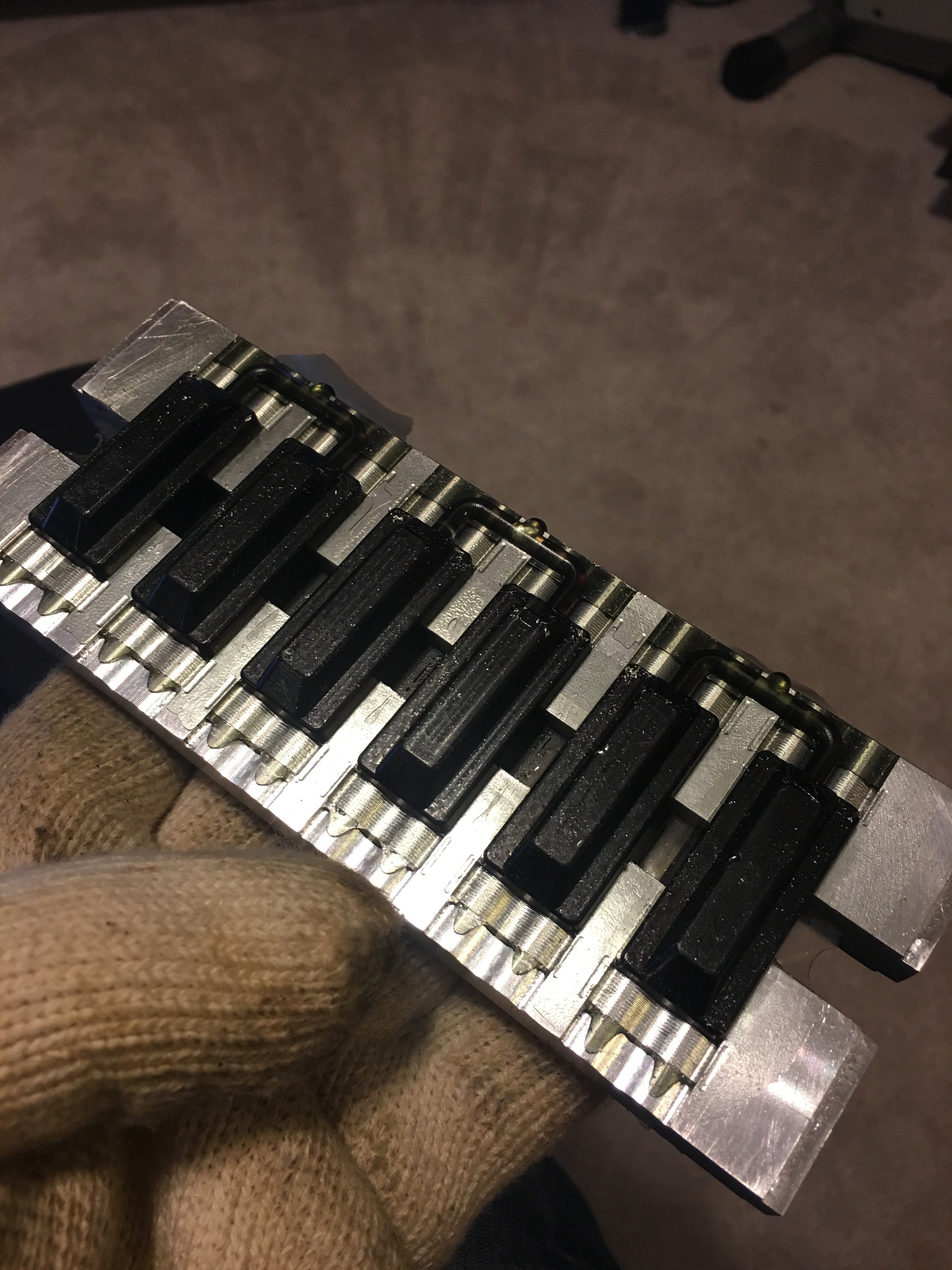
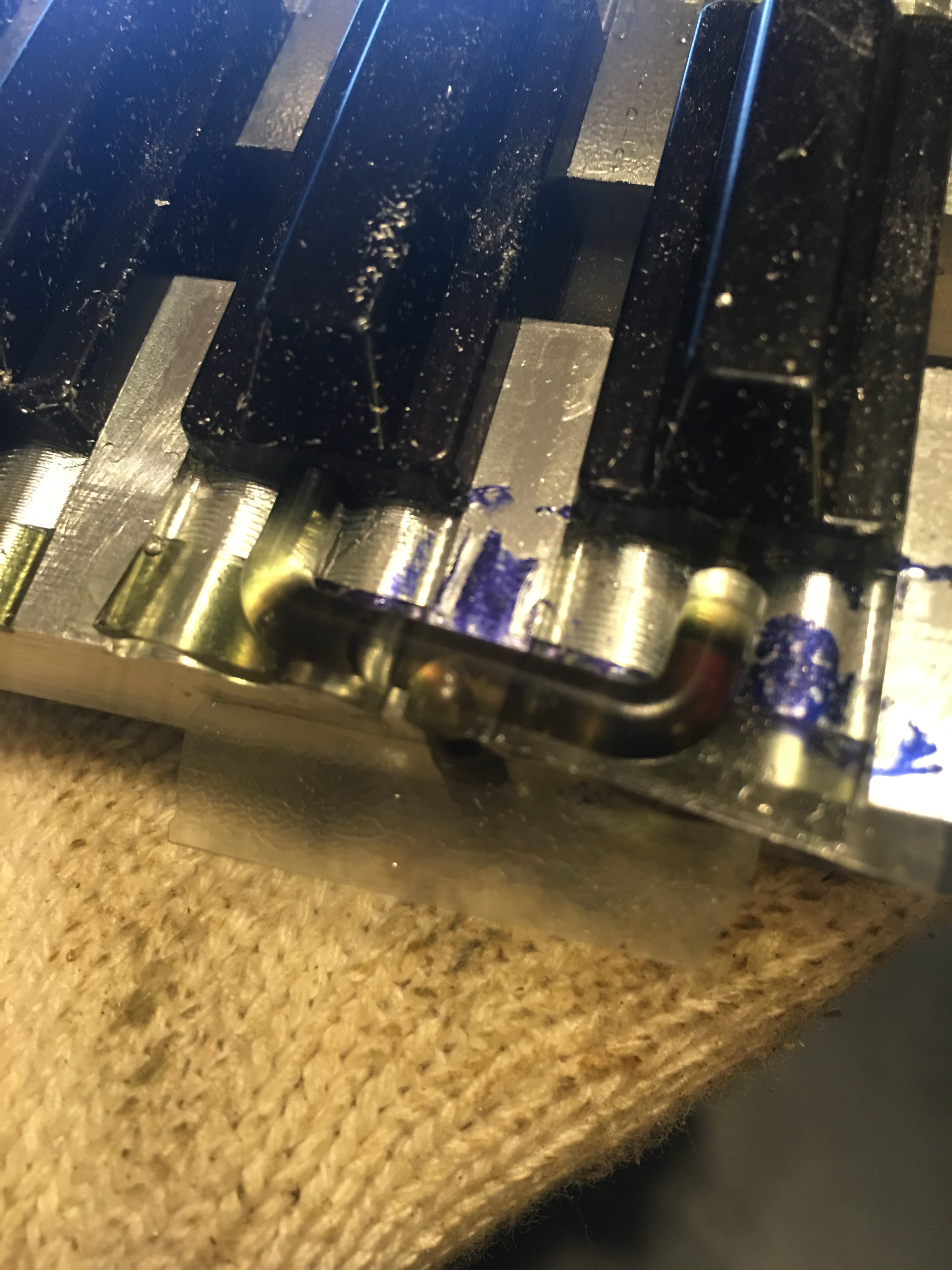
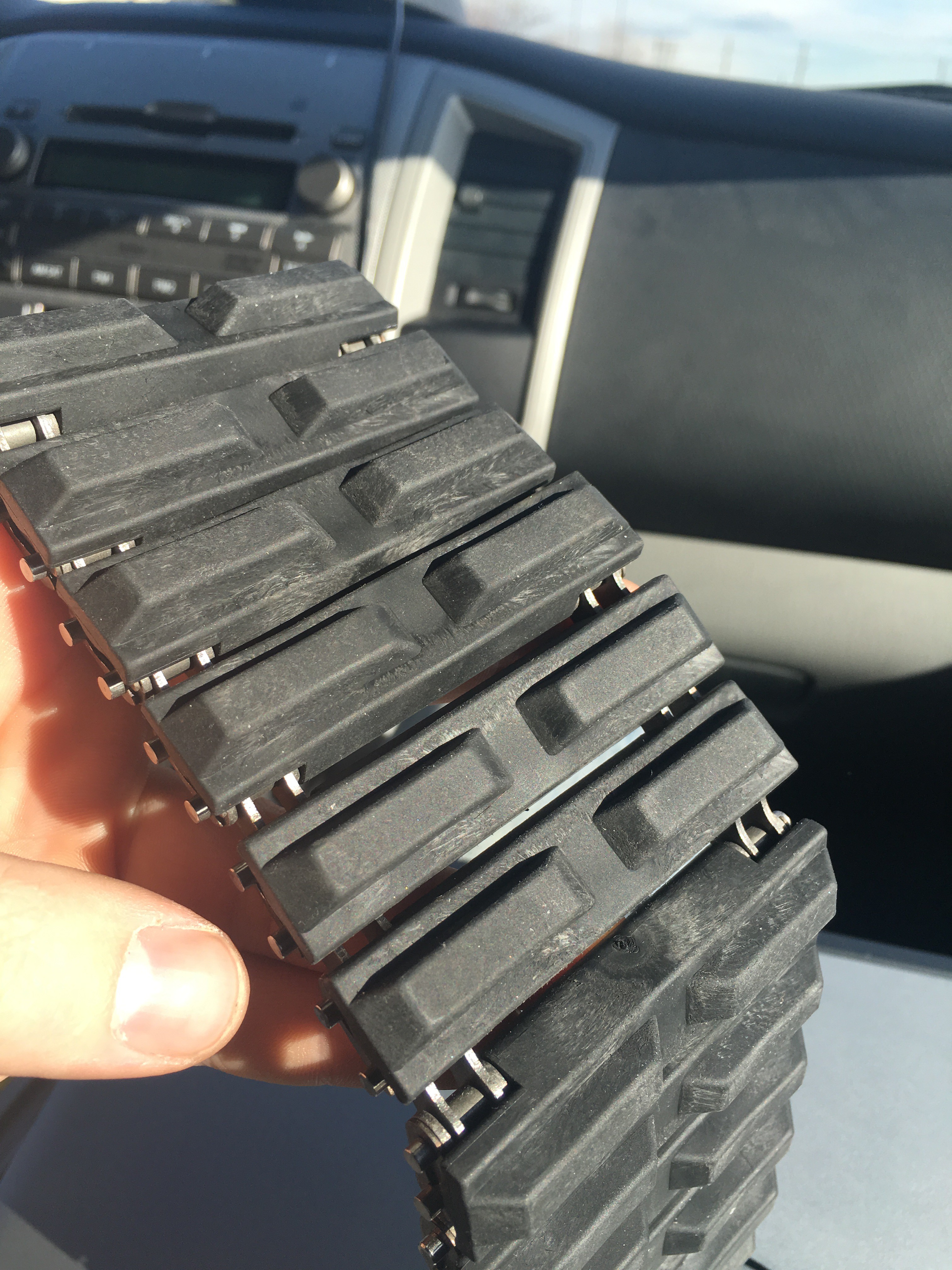
Notice that the drive sprocket can freely push crud out of the track where the teeth engage.

Hopefully you can avoid the same problem in yours.

  Are you sure? yes | no

jupdyke wrote 07/10/2015 at 20:09 point

Exuvo,

Thank you for your comment. I would really like to see more about your tracks and what you have tried. I did have the same though about material getting stuck in the chain. As far as I could see there were two options. 

Option 1:

Leave the chain open as you drive over material it could get stuck in the chain. But this allows the sprocket to push it back out. I was worried that this would increase the risk of the chain jumping off the sprocket.

Option 2:

Cover the chain on the drive side. This prevents material getting into the chain from the ground. But it could still get in from the sides. I felt that this was more likely to reduce the amount of material getting into the chain.

It was not so much an oversight as a design choice. I decided that covering the chain was a better starting point. The other part of this is that the track is rubber and not connected on the outside of the chain. This means that the sprocket can actually push material through the chain and the rubber tread will deform to let it out. I took a photo of this, but I can't seem to put the photo in the reply. I will put a picture in my latest log.

My plan was to build this design of the track, and get a working robot to drive around to test it out. I will do some experiments and see what works and what does not. I can always cut the rubber off my tracks and see if that works. I also have an idea about leaving the outside plate off my design and making it closer to the design on actual tanks.

  Are you sure? yes | no

Galane wrote 07/10/2015 at 08:26 point

How I make silicone molds. http://partsbyemc.com/pub/mold-making.htm As an alternative to shiny surface cardboard you can cover plain cardboard with packing tape. After trimming the meniscus edge off the mold it should be gone over with a grind stone in a Dremel to cut it down completely flat with the back of the mold halves. Another thing to note, it's best to NOT have the filling sprue at the top of the cavity. Have it enter down one side a bit (as in my example) then have vents out the top. That will prevent the resin from flowing to the sides and blocking some or all of the vents which can trap air bubbles at the top of the casting.

  Are you sure? yes | no

jupdyke wrote 06/05/2015 at 14:25 point

Alex,

Thanks for the link. I will definitely check them out when I move to the next level of production. Right now I have found a supplier for all the parts. The pins and chain are coming from Chinese companies and the injection molding is through a company that is here in the US. I was fairly confident in the pin and chain parts since they are very simple designs, and can't really be damaged in shipping. But I wanted to keep the injection molding local since my previous experience with molding is there is a lot of back and forth to get the mold perfect.

I will definitely check that site out and see what they can offer to help. Another quote is always a good idea. Thank you

  Are you sure? yes | no

Alex Rich wrote 06/05/2015 at 14:42 point

Cool, good luck with the molding.   I heard about seeed through Dangerous Protoypes, run by one of the HaD judges, Ian Lesnet.  He seems to have had a lot of success with them mainly for PCBs but also some mechanical stuff it looks like.  I may try them some time, I feel like the real value of a service like that is they know reputable vendors in China and can interface with them for you.

  Are you sure? yes | no

Alex Rich wrote 06/05/2015 at 13:19 point

http://www.seeed.cc/portals

Noticed this today scanning through the website at seeed studio.  Looks like they can assist people with offshore prototyping and manufacturing, might be interesting to show them your project rather than try to use Alibaba for everything.  When you are ready for that step and think you can make this a product I bet they would be awesome to work with.

  Are you sure? yes | no

Similar Projects

Does this project spark your interest?

Become a member to follow this project and never miss any updates