 jupdyke
Based on this research I decided that grousers and V shaped profiles were not ideal for an all-purpose tread profile. Maybe down the road I can develop additional profiles for specialized applications.
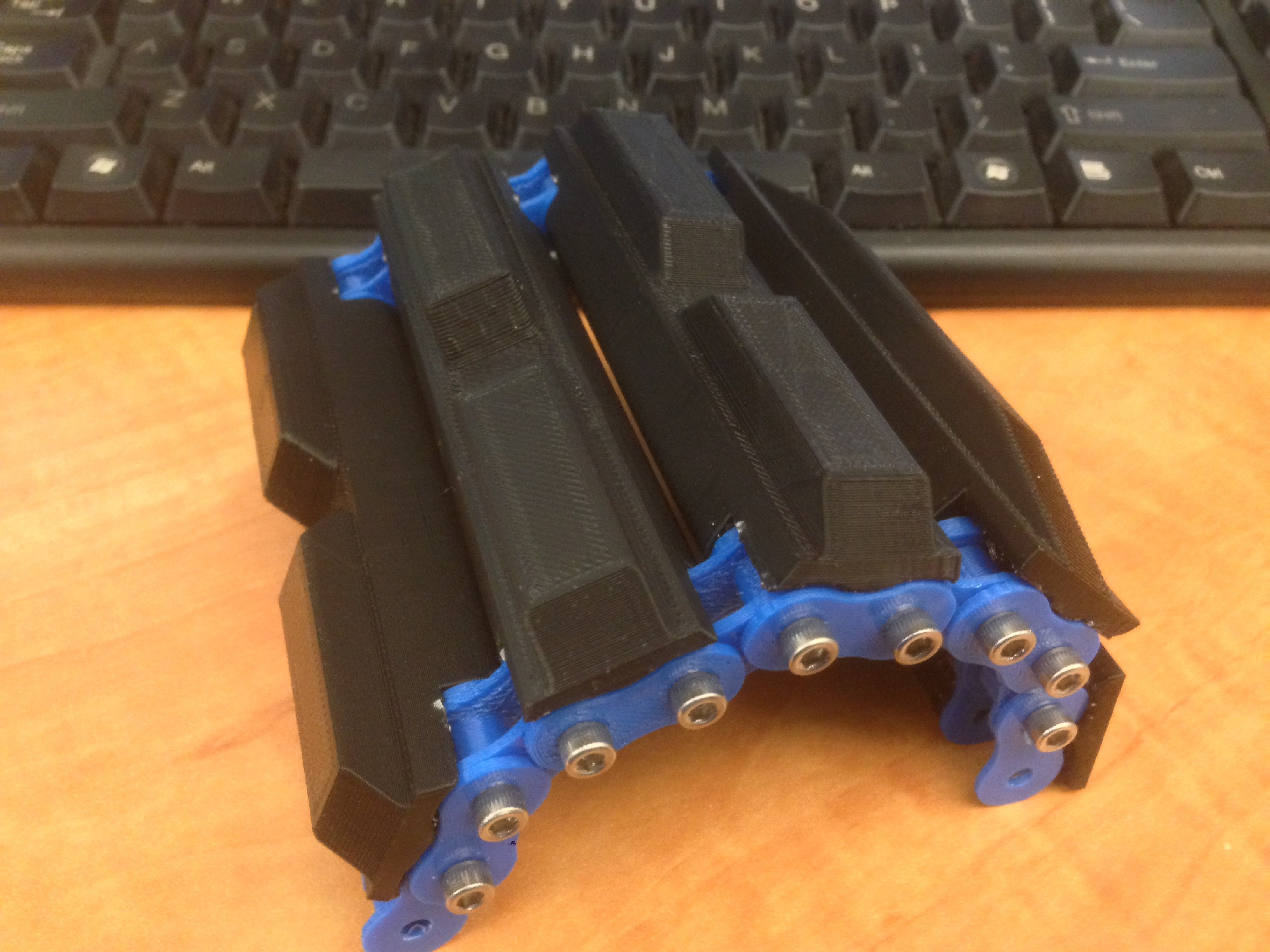
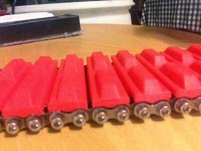
Based on this research I 3d printed several profiles and over time refined the profile until I was happy with a profile that was similar to a generic construction vehicle profile. I added generous tapers on the sides to make something that would turn easily, and hopefully not tear up my yard when I drove it around.
At this point I was finally getting enough parts to see how the links interacted with each other. I started to notice that the design only allowed the links to bend in one direction. Initially I didn't think that the tracks would need to back-bend. Since I had never seen tracks that went over a one sprocket and under another. This is very common in roller chain however. I designed the treads such that when the track was straight there would be very little gap between tracks. However, when I started prototyping the parts I noticed that when driving over objects having some back-bending is needed. Without it, the vehicle will see-saw over even small obstacles which will reduce the amount of track that is actually in
contact with the ground.
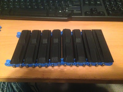
I started to revise the design and adjust the gap between treads to allow for some back-bending while trying to keep the gaps between treads as small as possible. This is where having a 3d printer is wonderful. I was able to 3d print various designs and connect them together to investigate this back-bending. I could simulate this in my 3d modeling software, SolidWorks, but it was not very convenient and it did not simulate any flexing of the parts. 3D modeling is amazing and lets you simulate a lot of designs, but then you need to build the prototype and hold it in your hands. 3D printed parts is the next step.
After integrating the design several times I decided that using 3d printed links for the chain did not simulate the final design well enough. The tolerances of the printer were not as tight as chain, and the plastic parts had too much flex. It was time to order some chain and upgrade. I ordered some #20, #35, and #40 chain on amazon. When it arrived I was surprised by how tiny the #20 chain was. This is another drawback of 3d modeling. You can get a feel for the scale of things in relation to each other, but not in relation to the world. I was working with parametric parts that scale from tiny to huge. But when I looked at them on the screen I never got that sense.
I started to disassemble the chain. My previous experience with breaking chain was pretty limited. Most times I only had to break a few links to change the length of the chain. I knew that breaking a large amount of chain would not be fun, but I also knew that this would only be for prototyping. I could build a robot to break chain in a larger scale or better yet find a supplier of unassembled chain. I originally thought that the pins would just be pressed in and need to be pressed out. However, the heads of the pins were domed and that made it much harder. I tried a few different methods to break the chain. First I used a dremal with a sanding wheel to remove the heads of the pins, and then I used a punch and vice to knock the pins out. This worked well, but was not very fast. Next I used the vertical mill. I put the chain in the vice and milled the heads of the pins off. This worked well, but without a custom fixture the chain did not sit perfectly. This way you could only mill about 8 links before the chain was either too high or too low and the height needed to be adjusted. It was not too bad and if I had to do it in larger scale I would make some custom vice jaws that held the chain better, or maybe even some 4th axis that could feed the chain through. This was a fun idea to think about, but a tangent project that could have easily side tracked me.
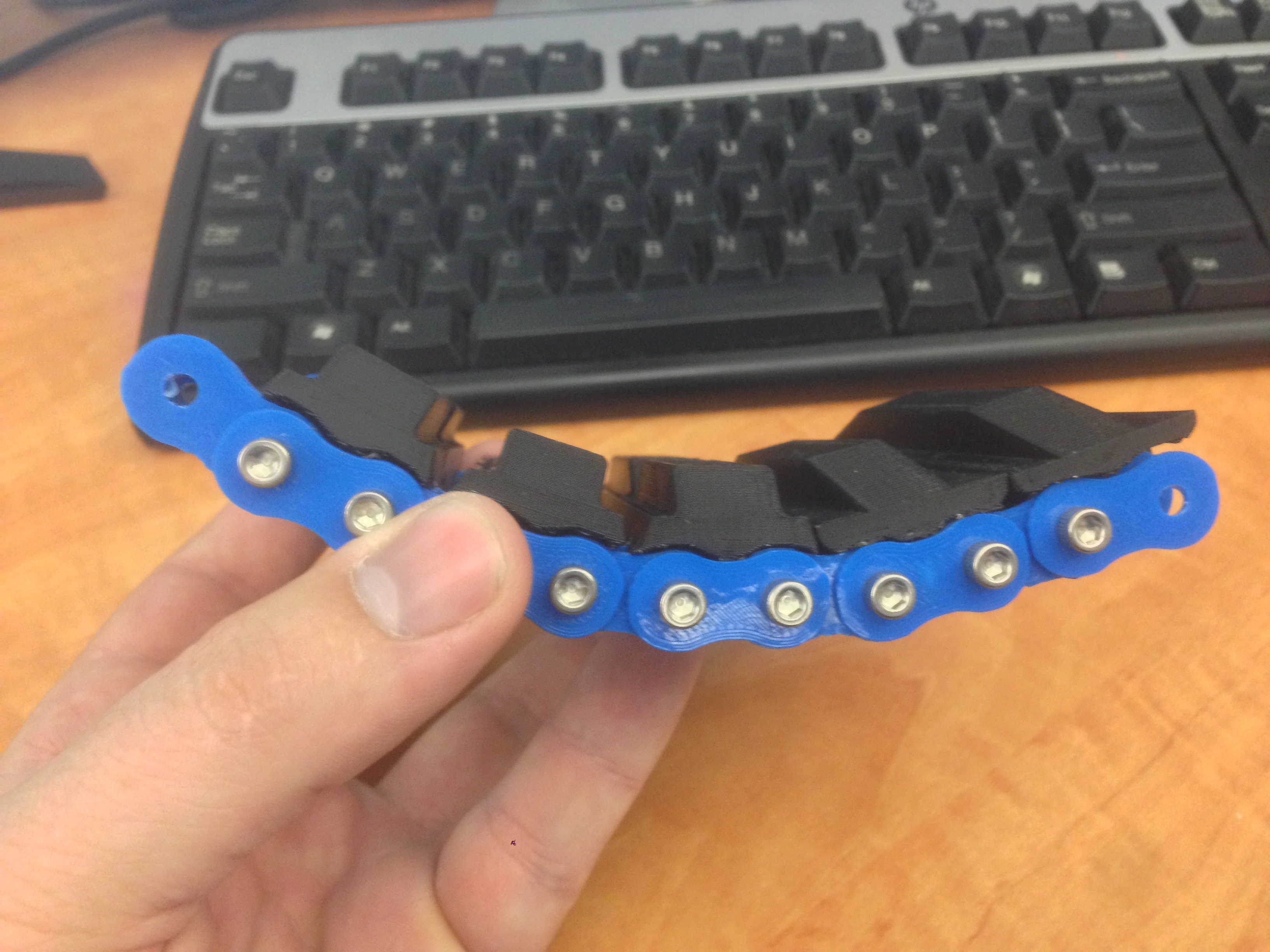
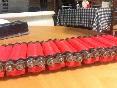
Once I had broken enough chain I replaced the 3d printed chain parts. The design was really starting to become a reality. It no longer felt like a cheap plastic toy, but had some weight to it. With the metal chain the links moved much smoother. My plastic parts fit together much tighter. I also noticed that the size of the holes on the chain did not match standard bolts as well as I hoped. For #35 chain a #6 machine screw fit well, but the other size chain did not match as well as I hoped. I could use metric screws for some sizes, but that was not ideal. Mixing imperial and metric in the same project was messy.
Discussions
Become a Hackaday.io Member
Create an account to leave a comment. Already have an account? Log In.