 Jonathan Bruneau
Despite it being over a year since my last project post, I'm still alive.
Quite a few things have changed since my last post. I’ve had a major job change, a house change, and a +1 to the family. Needless to say, I haven't’ been able to do much on this project.
This doesn’t mean that I’ve stopped working on it: au contraire! My pace might have slowed significantly, but I haven’t stalled.
I’ve completely revamped the power supply. Primarily in function of the larger 9W solar panels you can now find on Adafruit, Sparkfun, and other sites. I’ve also changed ECAD tools, opting for CircuitStudio. I’ve always liked the schematic+layout integration Altium tools provide, and now I can have my cake without breaking the bank.
In designing this
latest supply, I’ve made a few notable changes which made the board
significantly larger and more expensive.
These include:
- 5A input and output support for larger solar panels.
- 24V input and output support for larger solar panels and battery banks.
- FTDI header output for UART debugging.
- Firmware controllable output voltage and output current limits.
- Fun LEDs and much more!
This seems counter to all my previous logs, and you’d be right in thinking so. The rational here is three fold:
-
I don’t have nearly as much time to optimize the design.
The basic set of components required to provide MPPT support is a fixed cost that is hard to further optimize (proof, the rest of this project’s logs).
-
Addressing some of the shortcomings of the previous design requires additional costs, which are best amortized by pushing more power.
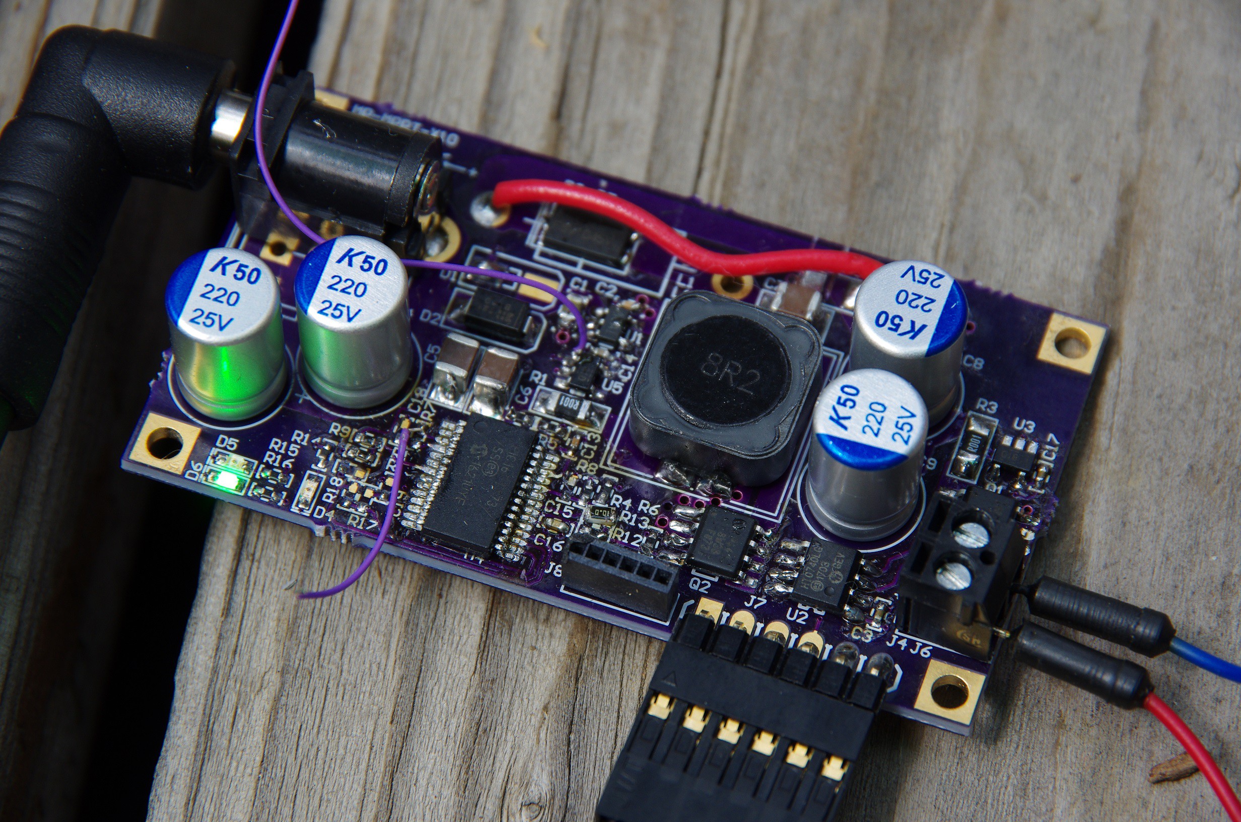
The design worked out fairly well. Powering this entire endeavor is a PIC16F1773, with 6 comparators, 6 DACs, and 3 OpAmps (no typos). As configured, this SEPIC power supply offers cycle-by-cycle input under-voltage protection (UVLO), intput and output over-current protection (OCP), and output over-voltage protection (OVP). The PIC is also setup to directly drive the FET with it's two beefy 100mA output drivers. Not bad for $1.80/PIC.
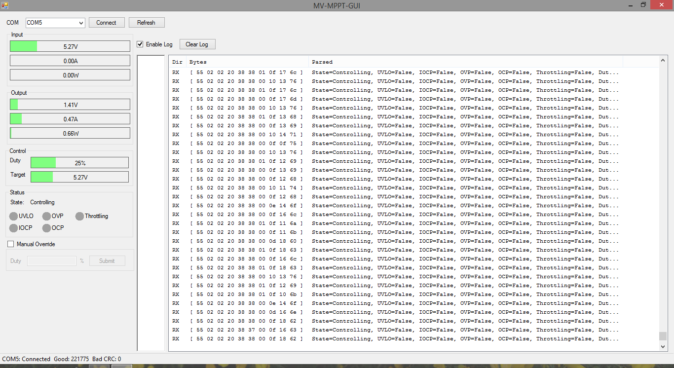
The design worked
well enough that I even bothered making a GUI to help me debug the
bringup issues (I connected a UART to the PIC) (note that the input and output current readings (and thus power readings) are completely trash, that needs to be addressed in a future spin of the power supply).
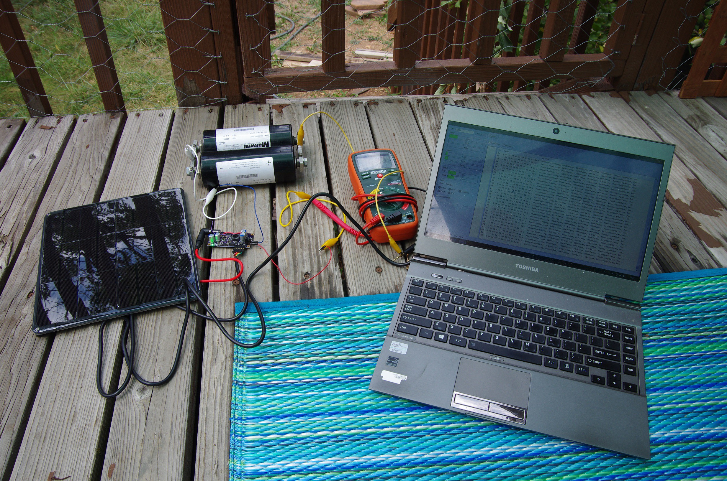
At it’s peak, I
was able to push out over 2A from the 9W/1.5A panel sold by Sparkfun. The output current was so high that I measured over 0.5V of drop in
the cable between the supply and the supercap bank alone!
I also managed over 85% efficiency, which is pretty decent (but not great yet).
All said in done, my bill-of-materials amounts to $8.17 @ 1000 QTY, not including the 4-layer PCB. For a 9W panel, this comes out to be slightly more than $1/W, which isn’t bad. But for a 3W panel, this is completely overkill.
The design turned out to be rather expensive in an attempt to remedy three major issues: Precision, Efficiency, Flexibility.
Precision
The internal reference of the PIC16F1773 has a +/- 4% tolerance across the entire temperature range.
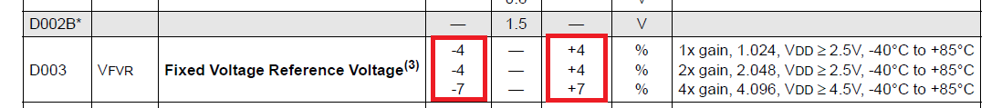
While this large tolerance doesn't matter much when measuring small analog
signals, when measuring a large 24V through a voltage-divider, it can mean the difference
between measuring 23.59V or 25.56V, which is a huge error margin.
Worst yet, the resistors used on the voltage-divider are all 1%! In itself, this tolerance will provide a measured voltage range of 23.66V to 24.70V. These two sources of error, combined, make a cheap voltage measurement solution unacceptable.
So I add a MCP1501 high precision external reference, and upgrade the output voltage sense resistors to 0.1%. This, naturally, adds cost.
Efficiency
Previous MPPT designs operate fairly well at light load, but as the output amperage increases, their efficiency drops. The losses come in many forms, but the most obvious paths include.
-
Losses in the forward voltage of the diode.
Switching and conduction losses of the MOSFET.
-
Current sense resistor losses.
-
DCR losses in the coupled inductor.
-
Leakage losses through the voltage divider and diode reverse current on the output of the SEPIC regulator.
Each efficiency loss has a solution, which adds cost.
-
I replaced the output diode with the FSV1045V, which boasts a forward voltage of 0.44V @ 10A! At 2A, that translates to a forward voltage of 0.3V, which is remarkable. Unfortunately, even with such a good diode, at 2A output I lose at least 0.6W, or 6.6% on a 9W panel. This also means my BOM increases: these costs $0.42 @ 1000 QTY. This diode is unfortunately required to connect multiple power supplies in parallel: using synchronous rectification does mesh well with parallel power supplies (without additional external signaling).
-
I replaced the SEPIC MOSFET with a lower Rds(on) FET (4.8 mOhm @ 18A, 10V) and a lower Qg of 26nC @ 4.5V. The $0.32 @ 1000 QTY price tag isn't great. I also decreased the switching frequency from 333kHz to 250kHz to help reduce the switching losses (it also increases my MPPT tracking precision, as discussed in this project log).
-
On the last SEPIC design I used a rather large current sense resistor: 0.1Ohm. Those 9W panels can output 1.5A, which translates to 0.225W of energy loss in the sense resistor. No problem: decrease the sense resistance, add an external differential amplifier to achieve the same results. Now I end up with a more expensive sense resistor, and an external current amplifier (I settled on the INA180A1).
-
The DCR losses through the coupled inductor can easily be remedied, but by lowering the switching frequency (to lower the switching losses), I end up needing a larger coupled inductor, which increases the DCR (I also need larger input and output capacitors) and the cost.
-
When not charging, there’s a leakage path through the resistor divider used to measure the output voltage. In the long run, this divider discharges the energy storage device. Easy fix: increase cost and use a MOSFET to turn off the divider when the supply is not connected. This is an especially expensive proposition given that an isolated gate driver provides the best results. I settled on the HT0740LG-G. It’s not cheap though: I’m paying $0.86 @ 100 QTY alone just for this chip. And actually, I cheated: I placed the high-side driver + FET on the output of the SEPIC, after the diode. Turns out the diode I chose has a pretty terrible reverse current leakage, and by placing the output FET on the output instead of the divider, I kill two birds with one stone.
Flexibility
Given that I want this MPPT supply to both be able to charge low output voltages (a.k.a. supercap) and high output voltages (a.k.a. 12V batteries) with any permutation of solar panel voltages, I have to deal with a lot more complexities. This is especially expensive in terms of the output capacitors required to control this tracker. I need 480uF-ish to have a properly behaving regulator, and with a 25V output rating, I have to suck it up and buy these rather expensive caps.
Conclusion
So where does this leave me? Frankly, I don’t know. The old adage says it right: “you can’t have your cake and eat it to.” If this was easy we’d have a solution out in the market by now for you and I to buy and use. I really don't like having that output diode burn 6.6% of the solar panel, continuously. I also don't like that for smaller panels (< 9W) the cost of this supply is far beyond the $1/W.
But at the same time, this is the best supply I've built yet. Maybe this is good enough.
Discussions
Become a Hackaday.io Member
Create an account to leave a comment. Already have an account? Log In.