 Jonathan Bruneau
Many moons ago I worked at a company who's quotidian routine included explosions of large capacitors and MOSFETs. During such inevitable mishaps my colleagues and I would meet up around the carnage, and after extinguishing the flames (literally), we would exchange interesting power supply related trivia.
During one such incident we got into the topic of solar MPPT supplies and one of the senior EEs gave a brief mention of SEPICs as a good choice for such use cases. Being young and naive, I quickly dismissed the topology for a variety of reasons (one being that it's hard to control) and never gave it a second thought.
Fast forward to today.
I am please to announce the latest MPPT power supply design fresh off the press: the SEPIC MPPT.
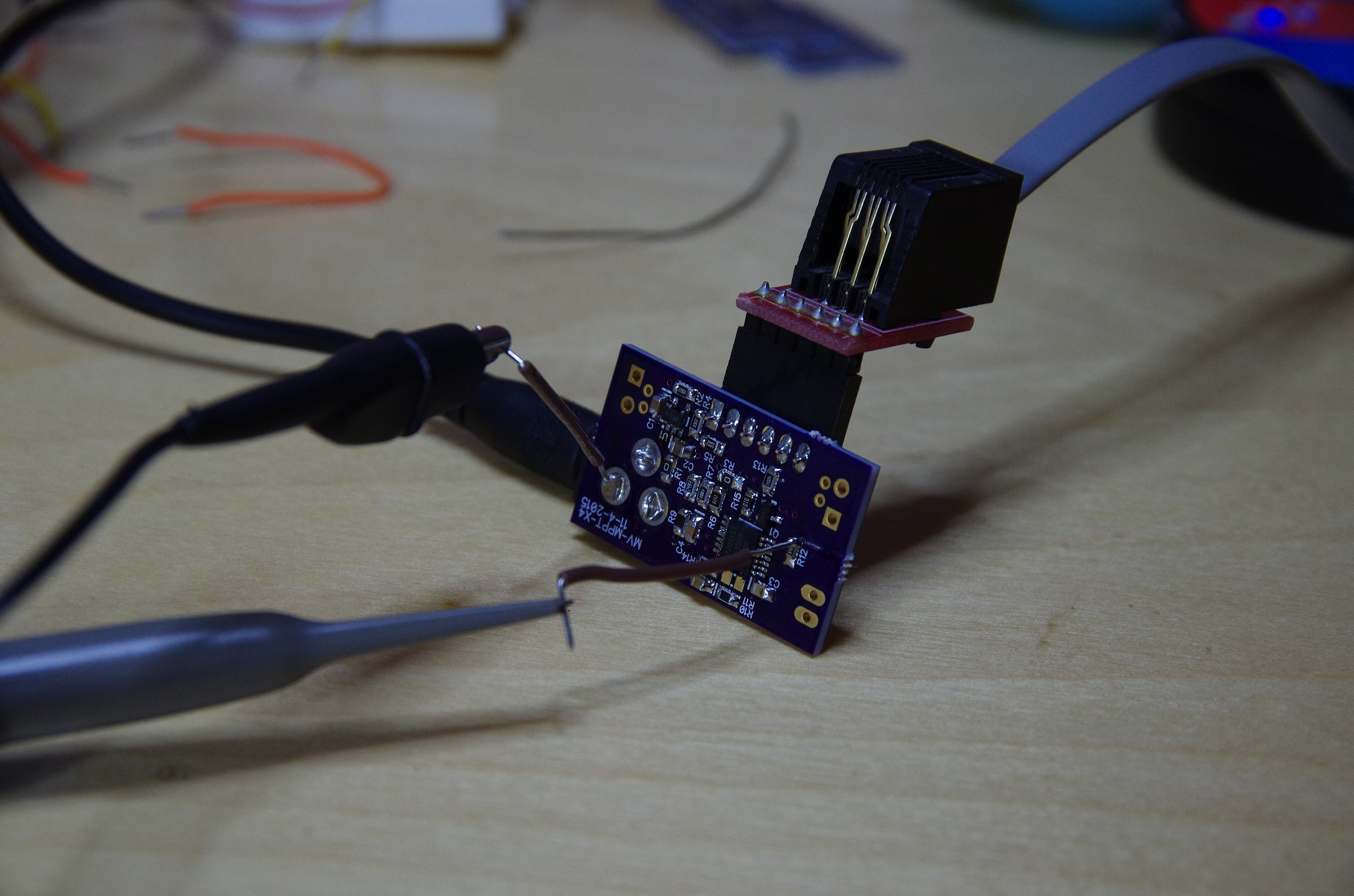
Front:
And back (with a lot more probes attached):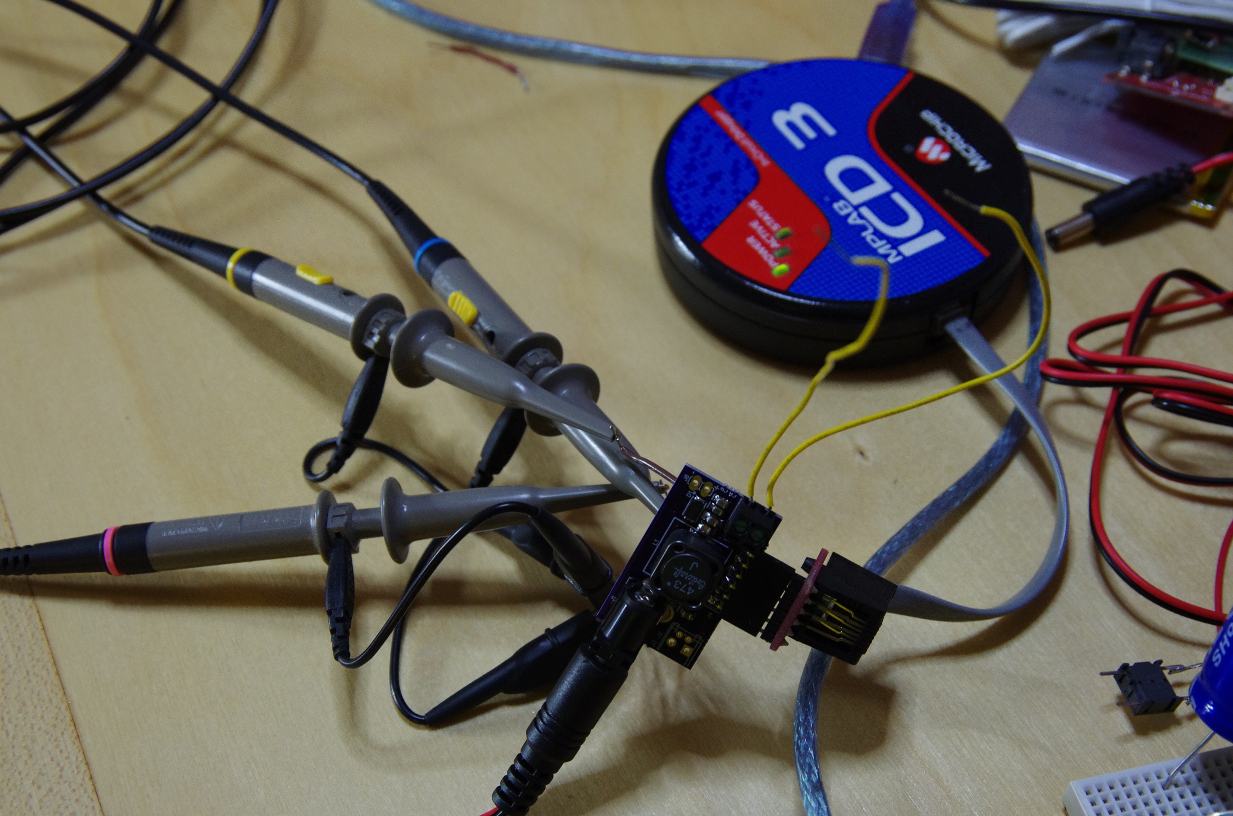
I have the supply up and running, and it's working well. There are a few things that need to chance, but I'm getting ahead of myself.
I've been eyeing the SEPIC for quite some time but never got around to actually building one mainly due to the cost of the coupled inductor (or 2 separate inductors) needed for the supply to function. But upon further inspection, the SEPIC offers many advantages over the other typologies.
- The SEPIC is a buck-boost topology.
- The buck-boost is non-inverting (unlike the Cuk).
- Unlike the buck and inverted buck-boost, this topology uses a low-side switch, which makes it easy to drive.
- Currents travel through the low-side switch only when it is closed, which makes for easy current sensing.
- Unlike the boost, no current is transferred to the output until the low-side switch is first closed.
So the trick was trying to find a coupled inductor with a sufficiently low cost to warrant a build. These are hard to find, especially when trying to keep the DC resistance (DCR) down to something that wouldn't ruin the efficiency of the regulator. These matters are made worst by the fact that I have to switch at a rather low frequency (sub-MHz), thus requiring a larger inductor. Some math pointed me to 47uH per coil, which made things tricky.
After a long search, I landed on Coilcraft's MSD1278 coupled inductor series. At $0.76 @ 1000 with a DCR of 0.18 ohms, these ain't cheap, but they strike a good balance of efficiency vs. cost. I found some cheaper alternatives, but their DCRs were significantly larger (sometimes a whole order of magnitude larger).
With coupled inductor in hand, I was ready to draw a schematic.

This is the same schematic as shown on the wikipedia page, but drawn slightly differently to group the coupled inductor into a single schematic symbol.
You can see the low side current sense resistor R15, which feeds into an Non-Inverting OpAmp. R10/R14 form the output voltage sense, and R12 is the current limiting resistor to the MOSFET gate.
Something worth noting here. Since the coupled inductor cost more than I wanted, I felt the need to reduce cost somewhere else. The current MCU I'm using (PIC16F1704) can output 25mA/port, with a grand total of 170mA for the whole part. This isn't a whole lot, but if the gate of the MOSFET is sufficiently small, could be enough to directly tie 4 pins directly to the MOSFET and remove the drive altogether.
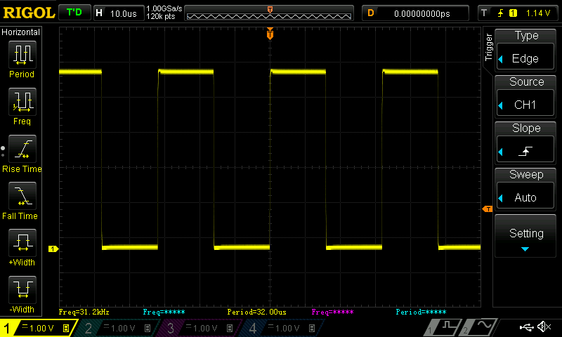
This was a gamble, but I was willing to take it. So I replaced R12 with a 50ohm resistor and took some measurements.
At 31kHz, the signal looks quite good:
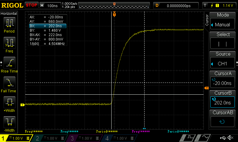
Upon close inspection you can see the rise and fall time.
Rise time plot:
Fall time plot:
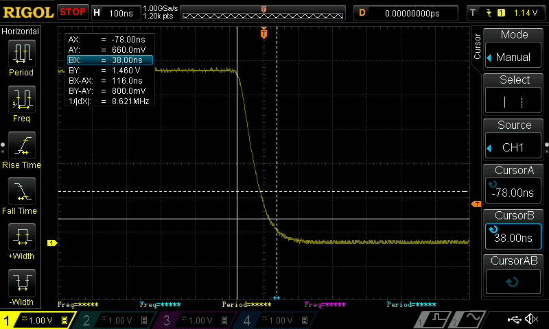
 That does *not* look like a square wave...
These results are encouraging, as removing the MOSFET driver saves $0.25 @ 1000, amortizing the coupled-inductor costs quite well.
So mission accomplished, right? Well...
There's one catch to this current design. In order to get the desired switching frequency (160kHz-ish), I have to significantly reduce the resolution of the PWM generated by the PIC16. This gives me a rather large PWM duty cycle step size: large enough that the solar panel voltage changes by 0.4V per step, which is quite huge. The large jumps in voltage for a small change in duty cycle makes the tracking of the MPP hard to maintain, and I had to significantly dampen the controls in order to achieve acceptable results.
This is not ideal as it would not track the MPP well in variable outdoor conditions. I could increase the coupled inductor size and reduce the switching frequency to achieve a higher PWM resolution, but this increase the cost of final design as well as reduces the efficiency.
A potential solution would be to switch to the new PIC16F1764, which offers a highly superior PWM peripheral that addresses my issue, but at a $0.40 rise in cost.
I have to percolate this over some. As always, suggestions are welcome.
Discussions
Become a Hackaday.io Member
Create an account to leave a comment. Already have an account? Log In.