Project Purpose
The Smart Grid Test Facility is designed to introduce engineering students to how a power grid works. The motivation behind this type of project is the current global challenges associated with fossil-based power generation. In order to adapt to renewable energy technologies, engineers must be familiar with the functionality of the power grid and the role of clean energy systems. Professor Horenstein, who instructs the university’s Power Electronics course along with other power and energy-related courses, formed this project. This test facility is expected to be used for experiments and demonstrations primarily in Power Electronics and Electric Energy Systems.
Features
- Interactive and modular
- User-friendly and safe user interface
- Three single-phase generators
- Real-grid transmission line simulation
- Variable RLC loads
- Versatile data collection system
- Automatic frequency stability
- Manual frequency control
Generation System
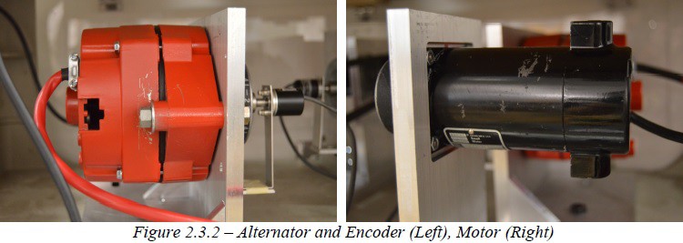
Per our customer requirements, it was crucial for the generation design to portray the mechanisms of power generation. In approaching this problem, we turned to a less efficient yet a more representative way of generating power for our grid. A single main generation point consists of a DC motor driving an alternator as well as a transformer used to step-down the output voltage. Due to various limitations, only two main generation points are made use of in the design. The third generation point is established through an AC/AC power supply, a simple yet useful addition to the grid generation, which also serves as the reference generator. In totality, the grid is supplied with power from three independent sources that are synchronized in phase and frequency.
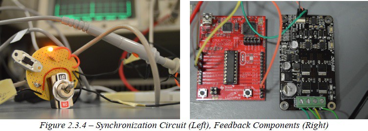
In any power system, as loads and generators change, power flow of the system changes. Therefore, our test facility is equipped with a frequency feedback system that stabilizes the three generators at 60Hz at 12Vpp. Students can change the simulated length of transmission line lengths in addition to load values and the system voltage and frequency will return to nominal values naturally. In order to ensure that the generators are synchronized upon startup, our test bench includes synchronization circuits that take two out-of-phase 60Hz sine waves and synchronizes them into one 60Hz, 12Vpp wave.
 Transmission Lines
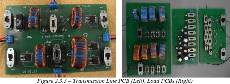
The transmission network is the backbone of the grid. It provides the electrical connections between generators and load points. On the power grid, transmission lines exhibit a characteristic impedance. The project’s transmission circuit boards model real-world line resistance, inductance, and capacitance over various distances. The purpose is to demonstrate the actual line losses associated with a three-generator transmission scheme as the mode of power transport.
Load Network
The modern electrical grid can readily be reduced into a system of sources, transmission lines, and loads. For every sized grid network the connection points for loads are found at the junctions between transmission lines, as such the loads provided with the test facility are designed bearing this connection configuration in mind. More so, these loads that have been provided with the system are modeled at high values (three orders of magnitude above the transmission lines) to simulate the relative power loss as power flows from generator to ground through a loaded network. Three basic loads are included with the test facility (resistive, inductive, and capacitive), each with an 8-bit binary setting allowing for each load to take 255 different values. In addition to these consumers, a model CITGO sign has been included that is backlit with LEDs as a representation of a luminous power consumer on the grid.
Data Acquisition System
In order to provide for experimentation and testing, this test facility includes a data acquisition system involving a LABJACK U3-LV and MATLAB that collects data from arbitrary points in the grid and provides key data points such as RMS voltage, RMS current,...
Read more »
 André
André
 Peter Babič
Very cool project. The Science Museum of Minnesota has a similar simulation but more elaborate including adding solar and wind to the grid, turning pumped storage (water and pressurized air), and manipulating grid usage. While that exhibit is aimed at the middle school and below education level, it incorporates many of the concepts included here. Good on you for leveling up!