Close
0%
0%

USB μC - USB PIC Bootloader

USB MSD Bootloader for PIC Microcontrollers

Similar projects worth following
A bootloader for PIC microcontrollers, that makes your USB capable PIC appear to your computer as a thumb drive. Programming can be done through MPLABX or by simply dragging and dropping your Intel hex file onto the drive. No programmer, drivers or software to install. https://github.com/johnnydrazzi/USB-uC

Supported Devices List:

PIC16F1459 Family:

  • PIC16F1454
  • PIC16F1455
  • PIC16F1459

PIC18F4450 Family:

  • PIC18F2450
  • PIC18F4450

PIC18F4550 Family:

  • PIC18F2455
  • PIC18F4455
  • PIC18F2550
  • PIC18F4550

PIC18F4553 Family:

  • PIC18F2458
  • PIC18F4458
  • PIC18F2553
  • PIC18F4553

PIC18F1XK50 Family:

  • PIC18F14K50

PIC18F45K50 Family:

  • PIC18F24K50
  • PIC18F25K50
  • PIC18F45K50

PIC18F46J50 Family:

  • PIC18F24J50
  • PIC18F44J50
  • PIC18F25J50
  • PIC18F45J50
  • PIC18F26J50
  • PIC18F46J50

PIC18F47J53 Family:

  • PIC18F26J53
  • PIC18F46J53
  • PIC18F27J53
  • PIC18F47J53

Features

  • Support for common development boards or customise your own.
  • Different crystal options, including NO_XTAL.
  • Drag and drop programming or program through MPLABX.
  • Read user flash as a PROG_MEM.BIN file.
  • Erase user flash by deleting PROG_MEM.BIN.
  • Read and write to EEPROM through a EEPROM.BIN file.
  • Erase EEPROM by deleting EEPROM.BIN.

  • Assembly Version

    Johnny05/01/2021 at 07:47 0 comments

    New assembly version of the PIC16F145X bootloader has been uploaded to github. Reduces the size to less than 0x800 words. The other microcontrollers will follow soon hopefully.

  • New Assembly Version

    Johnny07/22/2020 at 07:10 2 comments

    About 70% done writing a version for PIC16F145X in assembly.  Will be much smaller in size! I've had a request to make it small enough (under 0x7DB words) so that the first user instruction (user program starts) falls within the first program memory page. This is a requirement so that Great Cow BASIC compiled firmware will work with it. Practically an impossible task written in C. Hopefully won't take too long... If it's easy enough, I might adapt the assembly code to work with the other processors too.

  • Code on GitHub

    Johnny06/28/2020 at 11:59 0 comments

    Open sourced the project on GitHub.

View all 3 project logs

  • 1
    Setup Project

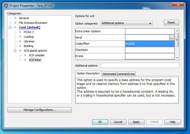
    Right click on your MPLABX project, and select Properties. Under XC8 global options, click XC8 linker. In the Option categories dropdown, select Additional options. In the Codeoffset input, you need to put an offset of 0x2000. (For PIC16F145X offset is in words, therefore 0x1000)

    If you are using the a J Series bootloader:

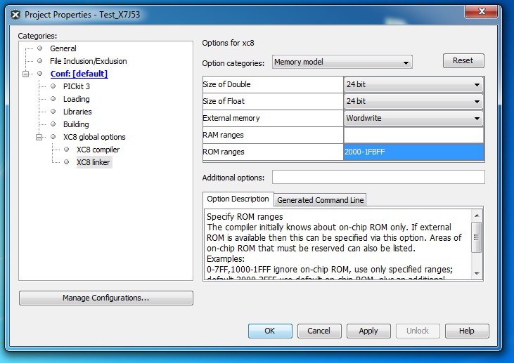
    In the Option categories dropdown, select Memory Model. In the ROM ranges input, you need to put a range starting from the Codeoffset to 1KB from last byte in flash. e.g. For X7J53, 2000-1FBFF is used. This makes sure your code isn't placed in the same Flash Page as the Config Words. That area is write protected.

    PIC18FX6J53: 2000-FBFF.

    PIC18FX7J53: 2000-1FBFF.

  • 2
    Download From MPLABX

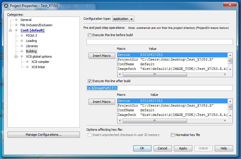
    You can get MPLABX to download your code every time you press build. To set this up, right click on your MPLABX project, and select Properties. Under Conf: [Default], click Building. Check the Execute this line after build box and place in this line of code (use the drive letter or name of your device depending on OS):

    Windows Example: 

    cp ${ImagePath} E:\ 

    Needs a space following "\".

    OSX Example:

    cp ${ImagePath} /Volumes/PIC18FX7J53

    Linux Example: 

    cp ${ImagePath} /media/PIC18FX7J53
  • 3
    Start Bootloader

    If you have previously loaded a program, reset your device or insert the USB cable whilst holding down the bootloader button. The bootloader LED (if used) will turn on indicating "bootloader mode" is active. If no program is present, just insert the USB cable. Your PIC will now appear in My Computer as a thumb drive.

View all 6 instructions

Enjoy this project?

Share

Discussions

Adam Kirby wrote 02/29/2024 at 18:45 point

Great project do you have any recommendations for development boards that are compatible 

  Are you sure? yes | no

John Rampelt wrote 04/11/2023 at 19:56 point

This has been an outstanding and reliable bootloader for the UBMP4 PIC16F1459-based educational microcontroller board (https://hackaday.io/project/184126-ubmp4-usb-picmicro-development-board) I designed for use in my high-school computer technology classes.

It takes a smaller memory footprint than Microchip's USB bootloader and, after my school board transitioned to a 1:1 Chromebook program, this bootloader enabled my students to keep developing their own PIC circuits as the microcontroller is seen as a USB mass storage device – no downloader software or drivers are required.

Highly recommended for anyone developing USB-enabled PIC projects! Thanks, Johnny for all of your work on this, especially the tiny assembly code version for the PIC16F1459. :)

John

  Are you sure? yes | no

Johnny wrote 04/23/2023 at 06:16 point

Thanks for the feedback. Great to hear it's still all working well for you and your students! Do let me know if you discover any issues.

I've wanted to use PICs in some designs at work recently and it's been tricky to source PICs right now, many of the devices originally supported by USB uC are out of stock (or at least their SMD package versions). This has got me motivated to update the bootloader and USB stack to support more devices. Around 70% of 8-bit PICs are supported now I believe. It's been fun revisiting this project :).

Cheers,

Johnny.

  Are you sure? yes | no

roman.l.senn wrote 02/07/2023 at 22:18 point

Very underrated and almost unknown project. 

I advertise here a use case how I put it to use in my own projects:

I use it together with "picstick_25k50", purple PCBs made at OSH Park.
They're easily populated with low part count and can be made by soldering novices.

It is the cheapest possible opensource microcontroller I know of. The circuit board is small, made with through-hole parts and can be used on breadboard, using wire-wrap or with JST connectors which makes it ideal for experimenting and building sophisticated machines.

libpicp and pictest are two skeleton projects I made for writing software libraries and programs compatible across a range of PIC12/16/18 and across the sdcc and the xc8 compiler.

I plan to use picsticks also with Pinguino IDE which is to some degree Arduino compatible.

picstick_25k50 layouts
https://github.com/kaza007/picstick_25k50

Library for different PICs (16F876A, 18F252, ....)
https://github.com/rsenn/libpicp

Test programs for different PICs
https://github.com/rsenn/pictest 

Thanks for your efforts in making this!

Roman


  Are you sure? yes | no

roman.l.senn wrote 02/07/2023 at 22:40 point

PIC pics, from a happy user 😉

https://imgur.com/a/yGAdq7w

  Are you sure? yes | no

Johnny wrote 02/19/2023 at 23:49 point

Glad to hear you've found this useful :). It was a passion project of mine for some time. Nice work on your Picstick, very efficient use of the PCB space. Thanks for leaving a comment!

  Are you sure? yes | no

Lucas Lopes wrote 05/18/2022 at 07:05 point

Hi Johnny, firstly let me congratulate you for the project, really neat! 

I am trying to use it with PIC14F1454, the HEX files provided work fine (both bootloader and test). But the Assembly version compiles fine (MPLAB v5.35 with mpasm), opens as flashdrive when connected, but when a file is dropped (same test file provided) it restarts without flashing and reopens empty.

Any help would be very appreciated.

Cheers,

Lucas

  Are you sure? yes | no

Eduardo Pinto wrote 06/19/2021 at 11:55 point

Hi Jonnhy,

Let me start to thank you very much for posting to make your work open source in github! It’s an incredible work and several steps further the MLA Microchip libraries! I already told my wife that I envy you 😊

I work in robotics and develop hardware for some years. I had tried your examples in one my current boards that uses a PIC18F45K50 with an ESP PICO D4, and everything works fine! I had some struggles to adapt your software to my board but now everything is working (all examples, bootloader and stack).
I wish only to say that maybe there is a fuse option that seems that is not the most correct one for PIC18F45K50. The PLL multiplier is set on file fuses.h as “PLLSEL = PLL4X”. I know that it works and I tested and confirmed it with the oscilloscope, but if you check the datasheet it should be PLL3X since the internal clock is set to 16MHZ. Seems that the MCU even with an PLL multiplier of 4X do not put out more than 48MHZ. I had tried with PLL3X and everything works also.. 

Once again Jonnhy, My congratulations for the excellent work!

  Are you sure? yes | no

Johnny wrote 06/20/2021 at 18:47 point

Thanks for your kind words Eduardo. Glad you find it useful 😊.. That fuse setting you found doesn't have effect because the PLL is in software enable mode. The PLL multiplier is set in the OSCTUNE register. When you select 16MHz/12MHz in the config.h file, the correct multiplier is selected in the boot_init() function in main.c. Cheers, Johnny.

  Are you sure? yes | no

Kees wrote 02/19/2021 at 09:56 point

Hi Johny,

I wonder if it is possible to implement this to a PIC24 device? Would that require major changes, or 'just' compiling it to a PIC24 with (minor) changes to registers and/or settings?

Does the PIC device need to have implemented USB or can it also work through an FTDI device (as my current design already includes a FT245 device)?

Greetings, CJ.

  Are you sure? yes | no

Johnny wrote 02/23/2021 at 08:00 point

Hey Kees,
Yeah shouldn't be too hard to implement on PIC24. Will need to adjust emulated FAT and MSD settings to reflect new flash size. New config word settings with bootloader protection. Small changes to product string and SCSI descriptor. Will need to add support for the processor you're using in various header files (many settings are adjusted depending on the processor defined). Flash block size for reading/writing/erasing might be different... Those are some things to modify off the top of my head, probably missed some. I had planned to support PIC24, but I don't have any dev boards to try it on.

  Are you sure? yes | no

Kees wrote 02/23/2021 at 08:18 point

Hi Johny,

Ok, thank you. I know then it is at least a feasable thing to try. When time permits I will dive into this and see whether I'm able to implement it.

Thank you for your answer!

Greetings, CJ.

  Are you sure? yes | no

Paul Antoine wrote 06/15/2021 at 00:54 point

Hi Johnny, I'm looking at using the PIC24FJxxxGU4xx series of USB enabled PIC24 devices. I'd happily send a dev board to you to facilitate implementation for that series if you'd like. Just let me know.

  Are you sure? yes | no

Johnny wrote 02/28/2021 at 02:49 point

Hey CJ,

Out of curiosity, which PIC24 device are you hoping to use?

I made a start at trying to make the bootloader work with the PIC24FJ128GB202. It's a lot bigger task than I thought. PIC24's USB peripheral is a bit different to PIC16/18 to allow for OTG. I'll have to update the USB stack first.

  Are you sure? yes | no

Kees wrote 03/01/2021 at 07:19 point

Hi Johny,

I'm currently using the PIC24FJ128GA306 device, with an external FTDI FT245 USB I/O. I've got that working ok, but I'm stuck at programming in Windows. Though nog completely unknown to Windows programming, it is just too much for me to focus me on that too.

For an updated design I wanted to switch to another PIC with USB, but though I manage the PIC in C quite well, USB is a too extensive protocol to figure out from scratch (with the time I've got to spend in it). For that my hope is on programmers like you.

For this updated design I was aiming at the PIC24FJ512GU408 (might become the 406 too). I need the pins for communicating with a TFT-display and for several stepper motors and other... stuff. The aim is an automatic pickup winder machine (for guitar pickups). I've got that already pretty much working ok, but I need (want) the firmware to be user updateable. Either through a 'standard' physical USB-connection, by a smartphone and Bluetooth (that would be cool too), by a USB memory stick, ...

I like the memory stick version because it is 'on the spot plug-n-play'. Bluetooth requires programming in Android and that is something I do not want to focus on (as with Windows, busy enough with the PIC :).

  Are you sure? yes | no

quickshoe wrote 01/14/2021 at 23:21 point

This is a very cool project. Is it possible to make this fully host controlled so that I don't have to press a button to reset the PIC and enter bootloader?

  Are you sure? yes | no

Johnny wrote 02/03/2021 at 04:16 point

Thanks.. At boot-up you could get the bootloader to check if the PIC is connected to a USB port (possibly check SOF flag) or just powered. If connected to a USB port run bootloader, if not run user application. Thus eliminating the need for holding the boot button, but reset button or reconnecting power is still required to upload a new user program (so not really less effort).. Downside to this is if your'e wanting to use the USB peripheral in your project, the bootloader would always start first and you'd need something like a boot button to exit the bootloader.. Not sure there's an elegant solution to this... I have made a MSD programmer version of this project that can program another PIC. The simple version doesn't need to have a bootloader or reset button. Simple version is for programming the target only (not reading, or accessing EEPROM). Might release that in the near future.

  Are you sure? yes | no

Jef wrote 11/23/2020 at 15:15 point

Hey Johnny, Is it possible that the LF devices are not supported? MPLAB is giving me the error "Part not supported" for my PIC18LF25K50. Or am I missing some kind of setting I have to do? It is critical for my application to use the LF version because I have a 3.3V supply. Thanks!

  Are you sure? yes | no

Jef wrote 11/25/2020 at 16:03 point

Confirmed: working for LF devices :)

  Are you sure? yes | no

jiyang wrote 06/28/2020 at 12:22 point

bangbang

  Are you sure? yes | no

Tachyx wrote 06/26/2020 at 19:13 point

I'm using 1455 and I can't re-program without unplugging and plugging the USB cable. Reset button will not do the trick.

  Are you sure? yes | no

Johnny wrote 06/27/2020 at 02:16 point

Hey, that's a strange behaviour. Have you checked your silicon revision against the errata document? From memory reset had an internal pull-up, but maybe try adding one. I'll run some tests at my end, my dev board didn't have a reset button, so maybe something I overlooked.

  Are you sure? yes | no

Johnny wrote 06/28/2020 at 06:21 point

I haven't been able to reproduce your issue at my end. Not really sure what could be doing that.

  Are you sure? yes | no

Tachyx wrote 06/29/2020 at 19:14 point

I have a pullup on MCLR pin. My device may or may not be bus powered. The RESET button works in either case to restart my code. I'm running Windows 10 and Windows will not enumerate the device unless I unplug the USB and plug it in again. I have to release the BOOT button a fraction of a second after plugging the USB or it will not be recognized and I have to unplug it again. My code does not use the USB and I explicitly disable USBEN.

  Are you sure? yes | no

Johnny wrote 06/29/2020 at 21:27 point

Sounds like your bootloader button (RC4) is floating? Or possibly a pull-up, instead of pull-down?... Make sure you're using the latest bootloader version, I just updated the bootloader and released the code. If you open config.h and main.c you can see how the bootloader uses the boot button.

  Are you sure? yes | no

Lagnajeet Pradhan wrote 07/08/2019 at 15:37 point

Hi, I am interested in making a Mass storage class device using PIC18F25K50. I am not interested in the bootloader part. I looked at the XPRESS example from microchip. The microchip example is a composit device with MSD and CDC. I only need MSD. I can read the readme.html file if I run the example in composit device mode but the file comes out empty when I modify the USB descriptor to make a MSD only device. It will be a great help if you can post an example code that shows how did you get MSD to work.  Any help is highly appreciated

  Are you sure? yes | no

Johnny wrote 07/08/2019 at 15:43 point

Hey, I have posted MSD examples using my USB Stack on GitHub. https://github.com/johnnydrazzi/USB-Stack . Hope it helps.

  Are you sure? yes | no

Lagnajeet Pradhan wrote 07/09/2019 at 07:43 point

Thanks. I got it working

  Are you sure? yes | no

igor.giavitto wrote 03/19/2019 at 18:01 point

Hi Johnny back to you again....
I did several tests with the PIC16F1455 without any positive results. Every time that i put the HEX file in the drive the pic restart and back again to the drive. That with your test program and mine.
I test the PIC18F14K50 and all was ok !!!
My set of PIC16F1455 are very old may be the first release, I will buy new IC may be my old one have some hardware bug.
Just another question about interrupt vector it's mapped at location 0X2008 and 0X2018 ?
Last question, I need to remove manually all data from address 0X000 to 0X1FFF from HEX file, the compiler non skip automatically any suggest?
Thank you in advance for your replay.

  Are you sure? yes | no

Johnny wrote 03/19/2019 at 22:26 point

Hey Igor, I'll check the location and get back to you, sounds right... Haven't come across the offset not working before, might need to update XC8, you can modify the hex file if you get desperate... This is an interesting problem you're having, I only tested the bootloader on a PIC16F1454, possibly there is some difference causing this. I'll have to get my hands on a PIC16F1455 and see if I can find the problem.

John.

  Are you sure? yes | no

igor.giavitto wrote 04/22/2019 at 15:33 point

Hi Johnny, just back form my business trip and did some test:

prepared a blink led program

1)  test PIC16F1455 DEVICE REVISION ID=1003 - not work, the software initialize correctly, I can see the drive, I copy the file but after restart nothing happen.

2)  test PIC16F1454 DEVICE REVISION ID=1006 - work, the software initialize correctly, I can see the drive, I copy the file and led start blinking.

I do not have any PIC16F1455 with new revision, I do not know if there are a bug in the firmware or in the chip.

3) test on PIC18F14K50 are ok too!!

Will be good if the firmware skip the boot section location if the compiler prepare a HEX file from the location 0x0000 with value 0x00 to location 0x1FFF.

Best regards Igor

  Are you sure? yes | no

Johnny wrote 04/22/2019 at 15:50 point

Thanks for the tests Igor! Yeah revision ID=1003 has a silicon bug. The errata says that the device can't write to flash with internal clock speeds over 4MHz. 

http://ww1.microchip.com/downloads/en/DeviceDoc/80000546F.pdf

That explains your problem. Unfortunately there is not a fix for this (that I'm aware of) as USB needs to operate at the same time as writing to flash. And USB needs 48Mhz, which only operating at 16MHz can provide.

John.

  Are you sure? yes | no

Johnny wrote 03/19/2019 at 22:38 point

Any chance you can check your ICs revision? The errata does mention flash writes not working on clock frequencies > 4 MHz for revision A2.

  Are you sure? yes | no

igor.giavitto wrote 03/16/2019 at 17:58 point

Hello,

I really like your project, I programmed a PIC16F1455 with the bootloader NO_XTAL, and all it's ok, When I reset the board I see the USB drive in my windows 10. I try to download the test example but nothing happen. Every time I restart the board I see the disk but the test program do not start.
Can you please telling me what the test program do? You use the led?

Thank you in advance Igor

  Are you sure? yes | no

Johnny wrote 03/16/2019 at 22:33 point

Hey Igor, I may have messed up the test file. I'll verify this. When you start the bootloader does your led flash fast three times on RC5? Also do you have the pull-down resistor on RC4?... I'm able to create a version of the bootloader and test file to work on a dev board I have, the button and led are on different pins for that. I may have forgot to put it back to normal version before compilation.

  Are you sure? yes | no

igor.giavitto wrote 03/17/2019 at 06:21 point

Hey Johnny thank you for your prompt replay, yes I followed all instruction and pullup and pull down was installed, in any case today I will bouble check but I’m quiete sure all it’s ok. Thank you fot your test.

Best regards

Igor

  Are you sure? yes | no

Johnny wrote 03/16/2019 at 22:36 point

a quick test you can do is create your own blinky test file and make sure code offset is 0x1000.

  Are you sure? yes | no

igor.giavitto wrote 03/17/2019 at 13:45 point

Hi Johnny,

thank you very much for your test, I will try to figure out, as soon as I found the problem I will write to you.

  Are you sure? yes | no

Johnny wrote 03/17/2019 at 00:11 point

Hey Igor, just tested the booloader and test file together, seems to work fine here. 

  Are you sure? yes | no

Santiago Jose wrote 02/05/2019 at 16:14 point

Currently I only have one pic for development, if I charge the booloader could I re-record another program in the section that is recorded by the bootloader? I do not want to lose the pic in case of having problems with the bootloader

  Are you sure? yes | no

Johnny wrote 02/05/2019 at 23:00 point

ah, I understand. The write protection bits in the config words just prevent your user code from being able to overwrite the protected areas. You can still write over it again with a programmer. The code protection bits prevent a programmer from reading back your memory contents (stop people from stealing your firmware). When I was first learning about PICs, I made the same assumption.

  Are you sure? yes | no

Santiago Jose wrote 02/01/2019 at 22:41 point

Hello, excellent work ... but I have a question, if I load the .hex in the pic, I could not load a different program because of the write protection?

  Are you sure? yes | no

Johnny wrote 02/05/2019 at 10:25 point

Hey, thanks. The bootloader protects itself and the configuration words when loading your hex file. Just be careful with your user code, that you haven't written code that writes to locations in flash that have the bootloader or config words. Some of the bootloaders have protection from this where possible, but it wasn't possible for all of them.

  Are you sure? yes | no

Santiago Jose wrote 02/05/2019 at 13:33 point

I recently acquired a pic18f24k50 to make tests, Do you have a bootloader without code protection for this pic?

  Are you sure? yes | no

Johnny wrote 02/05/2019 at 15:13 point

Not sure I understand your question. The user space is not write protected. It's a bootloader after all.

  Are you sure? yes | no

Muth wrote 03/21/2018 at 09:31 point

Great news for the 18F14K50, I should test it as I have some of them, just need to find some time :)

  Are you sure? yes | no

Johnny wrote 03/21/2018 at 11:40 point

I look forward to your feedback. The latest version has a EEPROM.BIN file you can open in a hex editor. You can read and modify the EEPROM through that file. I'll update the instructions tonight.

  Are you sure? yes | no

Alex wrote 03/06/2018 at 17:45 point

This looks great! Are there any plans to support more controllers? Or to publish the code, so that others could add additional controller support? 

  Are you sure? yes | no

Johnny wrote 03/06/2018 at 23:16 point

Cheers Alex. I have a few in mind I want to support. PIC18F25/45K50, and PIC16F1455. I have already designed some modules for 25K50 and 1455. I think the J series will be easy to port. I had a go at the 45K50 the other day, with some difficulty. I'll keep trying on 25/45K50, they seem to be popular.

  Are you sure? yes | no

Muth wrote 03/06/2018 at 13:56 point

Very nice ! Will you keep your code closed ? (which I understand perfectly)

  Are you sure? yes | no

Johnny wrote 03/06/2018 at 14:28 point

Thanks Muth. Hopefully it gets used other than just me. I'm still undecided about opening the code.

  Are you sure? yes | no

Jarrett wrote 03/06/2018 at 17:47 point

Yeah, totally your call. :)
If another data point is useful, I would totally retarget this for a different chip - Maybe PIC18F14k50 - If I had the source.

  Are you sure? yes | no

Johnny wrote 03/06/2018 at 23:24 point

I'm working on porting the 45K50 next, that should be similar right?

  Are you sure? yes | no

Jarrett wrote 03/08/2018 at 17:19 point

That'd be cool. That's a good family.

  Are you sure? yes | no

Johnny wrote 03/10/2018 at 08:47 point

X5K50 parts are now supported.

  Are you sure? yes | no

davedarko wrote 03/02/2018 at 08:03 point

So what's the current status, is it working yet?

  Are you sure? yes | no

Johnny wrote 03/02/2018 at 14:41 point

Hey Dave, yeah firmware for X7J53 is working well. Plan on compiling with XC8 Pro some time over the weekend to see how small I can get the bootloader. I'll release the hex after that hopefully.

  Are you sure? yes | no

Similar Projects

Does this project spark your interest?

Become a member to follow this project and never miss any updates