 Stefan Lochbrunner
I was thinking about what else to put on the panel but couldn't come up with something original. Since the most essential parts for a 'starter kit' (buttons, LEDs) are already there I was thinking what the next step would be. In most tutorials[1] this next step is controlling something that requires more voltage or current than the MCU can deliver (besides using some special IC or a display). For this reason and because I need a PWM driver for other projects I threw together this MOSFET breakout:
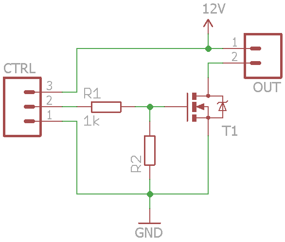
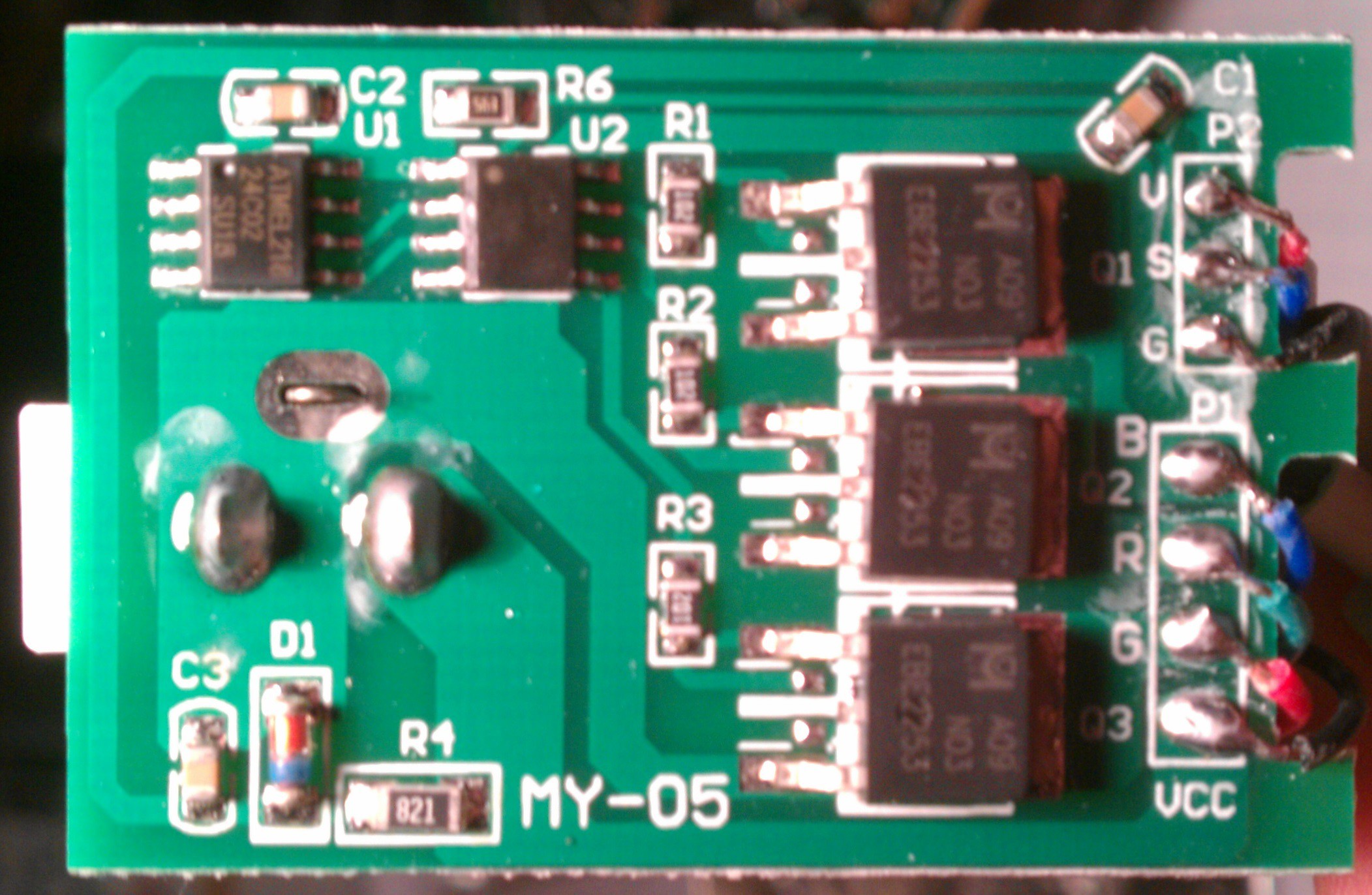
My sources for the schematic don't agree on one correct version for a MOSFET based driver and this cheap RGB LED driver that came with a LED strip even does something in-between:
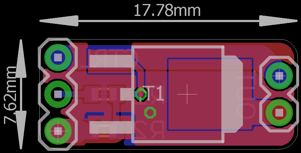
Therefore I added the footprints anyway and will populate them as needed. I don't see why a MOSFET would require a voltage divider or a series resistor at the gate, but I'd be happy if anyone could let me know the reasoning behind that.
The pinout seems to be pretty common and since pin 2 and the tab are internally connected in a lot of cases[1] this board should also work with SOT-223 packages and as a general breakout thereof.
[1] citation needed
Discussions
Become a Hackaday.io Member
Create an account to leave a comment. Already have an account? Log In.
Well sometime you want a series resistor (about a few ohms) depends on the driver circuits as some of them with bad layout can overshoot/undershoots. We also ran into the case of parallel MOSFET's where the interactions between two MOSFET's has caused some hard to track down oscillations as the MOSFET gates are not just simple inputs - there are capacitance coupled to the output too. Adding in the resistors eliminated the high frequency oscillation issues. Probably you have much bigger headache on the breadboard before this becomes an issue.
I got burnt a few times (and literally too) for not sizing the MOSFET drivers properly. One case the PWM chip blows up randomly as its driver was under rated and couldn't handle the capacitance load (thermally) and the other with the MOSFET running hot. Both cases I used drivers, but they were not sized correctly. See here for sizing: https://hackaday.io/project/4993-dual-channel-battery-chargeranalyzer/log/16890-power-components-more-nickel-dime-time
Make sure you use thick and short tracks for the gate and watch the ground returns for it too. i.e. route it as a critical high speed signal. The transient gate current can be in the 1 amp or higher range. Having all that on a PCB would go towards making it easier to prototyping.
Are you sure? yes | no
Thanks again for the info and the link, this should give me a place to start looking into the topic. I don't have experience in properly sizing the traces for this magnitude of current. I would have chosen the trace width depending on the copper thickness such that the current density is in a reasonable range but the datasheets should also have a reference design for the layout.
Are you sure? yes | no
Your PCB would be small enough that a 10 or 12 mils tracks would be fine. The important part is ground plane under the track be continuous and that there are ground vias connecting between the driver and MOSFET. Let me know when you do a layout, I'll help you out. It is only a high current pulse for 20-40ns, so thermal is not an issue..
Are you sure? yes | no
They might put a high value pull down resistor as MOSFET have high input impedance may pick up static charges at input when power is off.
1K is too high for MOSFET series resistors, but they may use it to slow down switching transitions which might be useful for EMC purposes.
The MOSFET spend a lot of its time in the linear region not completely switched on leading to higher losses and this is not recommended for high frequency PWM as you have a lot more transitions. I would rather see a proper high current MOSFET gate drive + MOSFET.
Are you sure? yes | no
Thanks for this info, I kind of figured you'd want a pull resistor in there. So if you're not worried about EMC it'd be better to omit the series resistor, therefore speeding up switching transitions and spending less time in the linear region, right?
I'll definitely look into implementing a proper driver especially since I'm also planning a 3-channel device, thanks for the suggestion!
Are you sure? yes | no