0%
0%
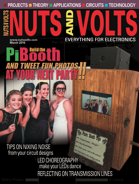
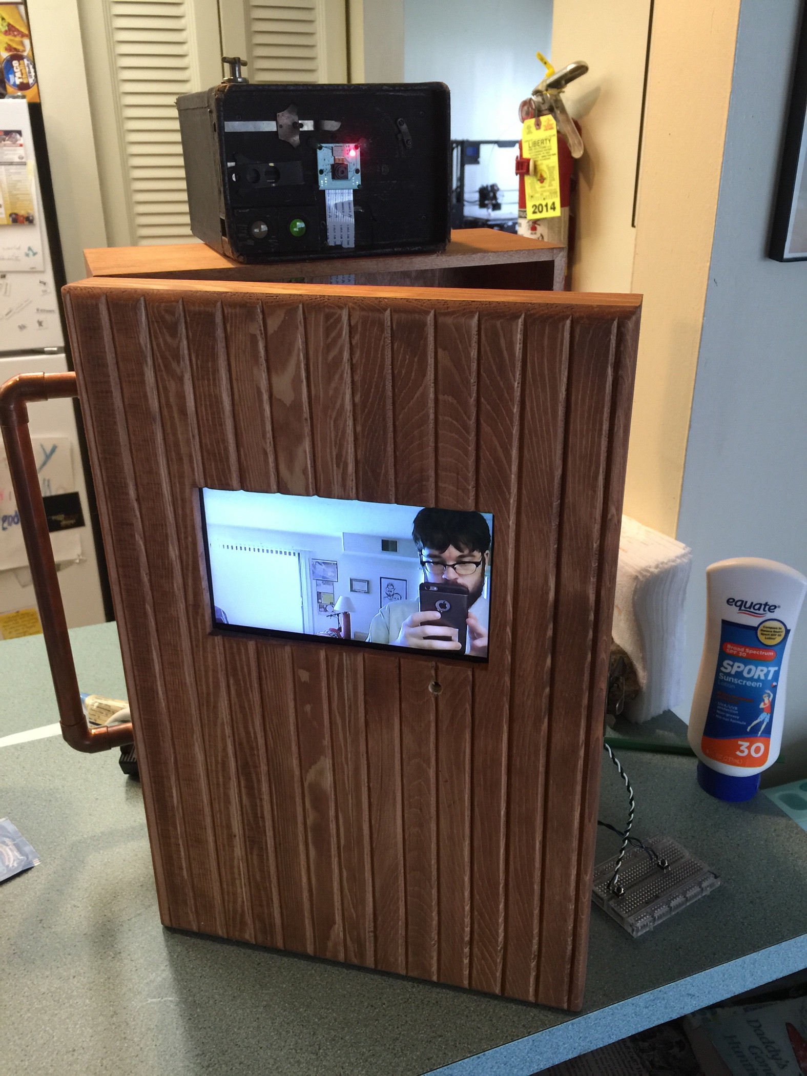
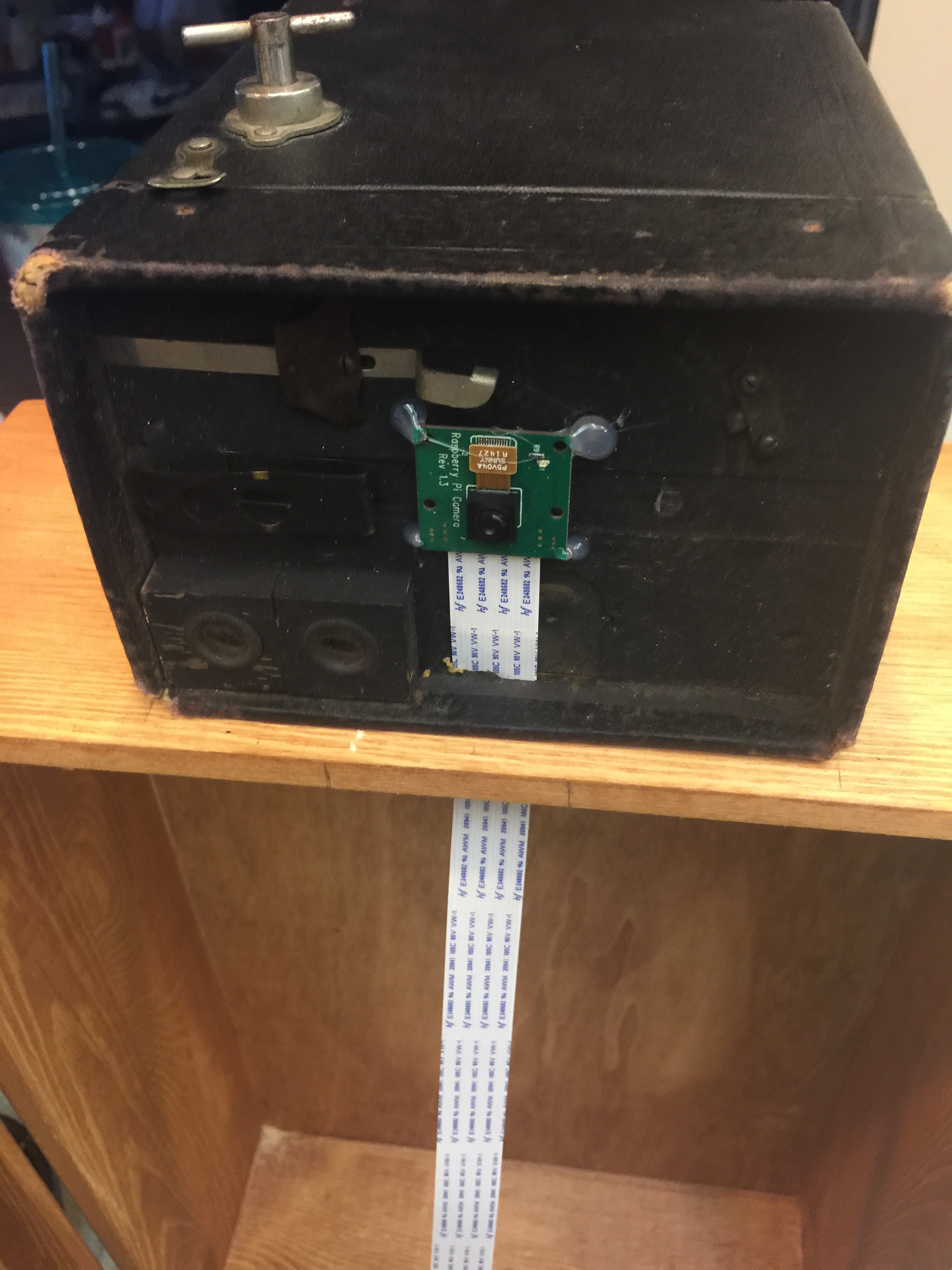
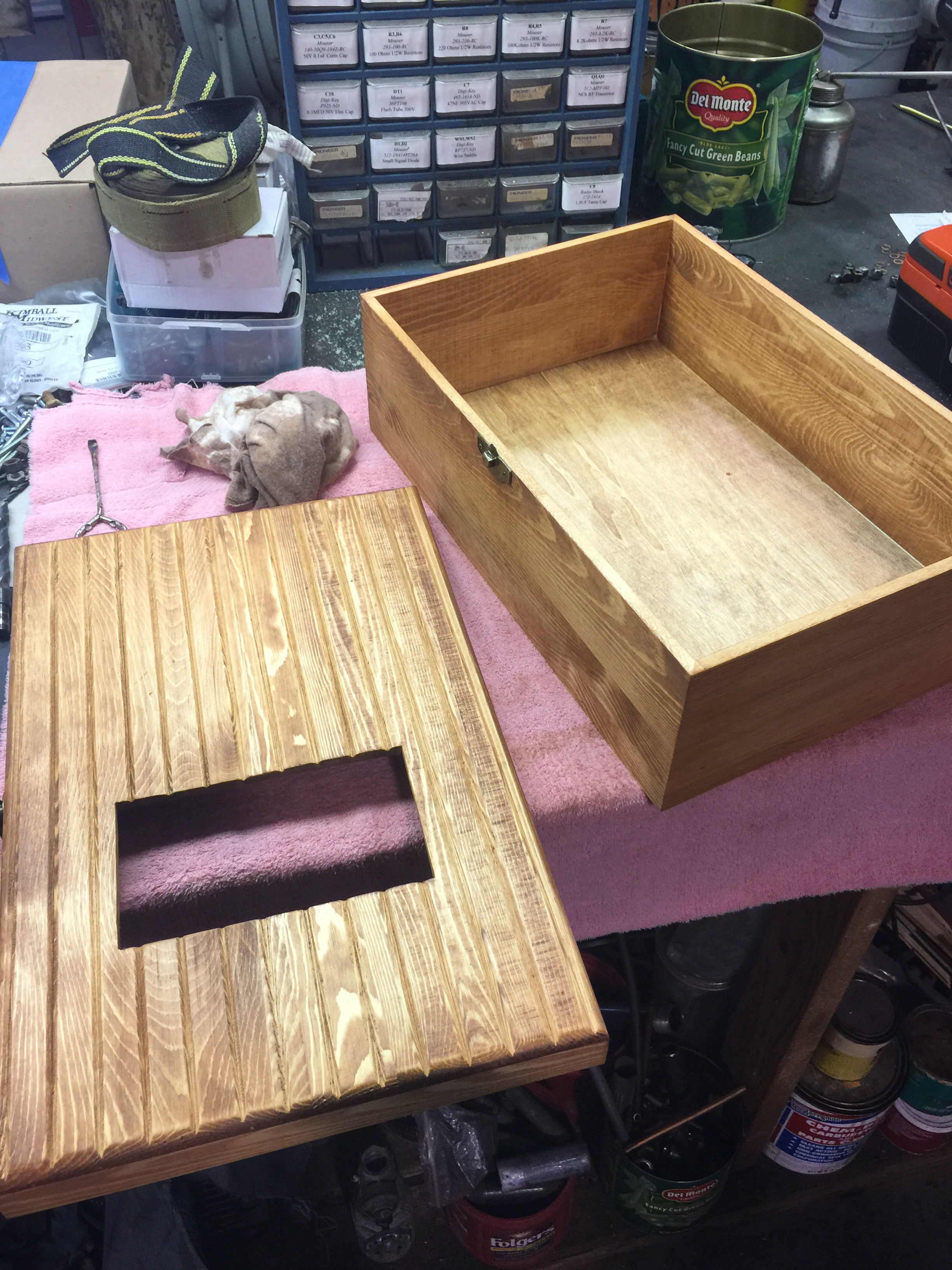
PiBooth
RaspberryPi photo booth to help capture memories at your events.
 John Leeman
Become a Hackaday.io member
Already have an account? Log in.
Just one more thing
To make the experience fit your profile, pick a username and tell us what interests you.
Pick an awesome username
hackaday.io/
Your profile's URL: hackaday.io/username. Max 25 alphanumeric characters.
Pick a few interests
Projects that share your interests
People that share your interests
 Joseph Eoff
 Kevin Kadooka
 mulcmu
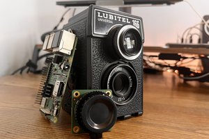
 Gradivis
Is it very difficult to change the code to use gphoto2 (dslr camera)?