Close
0%
0%

uSenseCam

Open source multispectral array camera for vegetation analysis for UAV.

Similar projects worth following
The aims of the project is to create an small and practical multispectral array cameras for UAV. This system is composed by 2 to 6 CMOS sensors. Each sensor use an specific wavelength filter to build a multi-spectral image.

The spectral response of the sensor would be from 400 nm. to 950 nm. The system provides the possibility to select an specific wavelength range by changing the band-pass filter for each sensor.
The specification are:

- Connection via micro usb for calibration (Focus,white balance).
- Simultaneous shooting (array cameras).
- Sd card image saving.
- Custom bandpass filter.
- CS mount lens.
- At least 2MP.
- Analog live video streaming.
- Size for one camera: 35mm x 35mm x 50mm (without lens.)
- Weight for one camera: 120 gr.(without lens and filter).

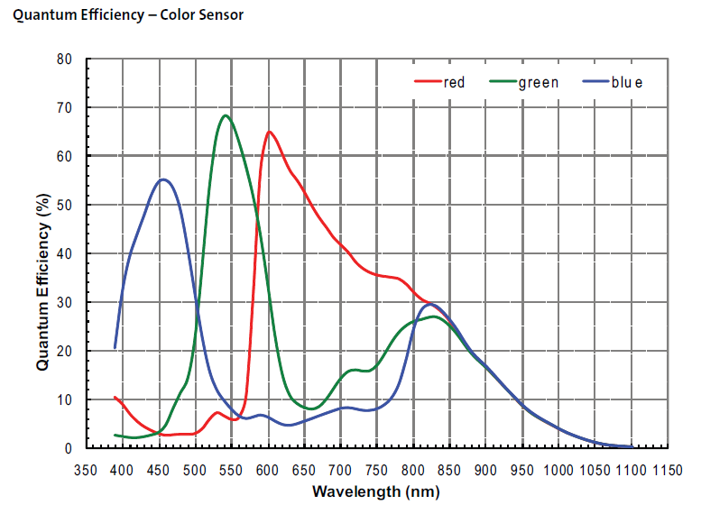
uSenseCam would monitor the plants reflectance of visible and near-infrared radiation.

Farmers would use aerial multispectral images taken by uSenseCam to monitor the plant growth and other functions helped by vegetation indices . The future application will be biology, forestry, environmental research, surveillance, and infrastructure inspection.

The chosen bands are based on LandSat 7.

  • 1 × Raspberry Pi (In future would be replaced with Oduino-W) FIRST APPROACH
  • 1 × USB Camera with Aptina AR0130 Sensor FIRST APPROACH
  • 2 × I2C micro SD Reader FIRST APPROACH / SECOND APPROACH
  • 1 × SMT32 F4 Dev Board (In future will be replace with Teensy 3.1) SECOND APPROACH
  • 1 × MT9D111 Camera Module SECOND APPROACH

  • Aptina AR0130 has arrived

    Jose Barreiros07/11/2015 at 05:00 0 comments

    We plan to use Aptina AR0130 USB Camera for testing the UVC drivers on Raspberry also because it has a great spectral response, we're going to do some NIR photo tests.

  • First Approach

    Jose Barreiros07/08/2015 at 06:33 0 comments

    The first approach goal is interfacing an USB camera with Raspberry Pi, triggering the camera with a button, saving a photo and finally do these tasks with an auto-run program on startup.

    In the following project logs I'll post details on the development process.

  • Checking MT9D111 communication

    Jose Barreiros07/08/2015 at 06:10 3 comments

    For checking the MT9D111 two wire interface I started wiring the camera module to an Arduino Nano. Then, I programmed the Arduino based on the 16 Bit Register Read and Write Examples in page 9 to 11 of the Developer Guide.

    Wiring:

    MT9D111 ------ Arduino

    GND ------------ GND

    XCLK ----------- D9

    VCC ------------ 5V

    GND ------------ GND

    SCL ------------- A5

    SDA ------------- A4

    After a few hours trying to generate the 8Mhz clock on Arduino, I realize that timer1 could perform that task without compromising other functions such as delay() and millis().

    Finally, the results were successful, Arduino could write and read registers in MT9D111 Camera Module with these two custom functions:

    write_reg(register_address, page, data_msb, data_lsb)

    read_reg(register_address);

    /*
    Author: Jose Barreiros
    Date: 01/June/2015
    
    
    This code is Arduino Nano compatible, the READ CODE is based on the work of Anthony Balducci:
    https://github.com/anthonybalducci/MT9D111-Teensy-3.1/blob/master/MT9D111_16-bit_Register_Read_Example.ino
    
    
    Useful note from Anthony Balducci code:
    "The MTD9111 Developer Guide states that 0xBA and 0xBB are the default read/write addresses respectively.
       However, it is important to note, while converting 0xBA and 0xBA to binary at first 'appears' to give us
       two distinct addresses:
       
       (Write) 0xBA --> 10111010
       (Read)  0xBB --> 10111011
       
       The two values only different in their LSB (least significant bit), or in this case, the first value on the
       'right'. The '0' / '1' in this position is what specifies the write (0) or read (1) condition accordingly.
       In the Arduino language the LSB read/write portion is already built into the Wire.write / Wire.read commands,
       thus the original register addressess specified must be truncated by the read/write bit to seven bits, leaving 
       us with 1011101 --> Ox5D in both cases."
    */
    
    
    #include <Wire.h>
    #include <avr/io.h>
    #include <util/delay.h>
    #include <TimerOne.h>
    #include <avr/interrupt.h>
    
    
    #define TMR1 0  //Timer1 used for 8Mhz PWM Output
    void setup()
    {
     delay(500);  //Initial delay
     Wire.begin(); // join i2c bus as master
     Serial.begin(9600);
     Serial.println("MT9D111 Camera Module + Arduino Nano");
     Serial.println("Read and Write 16-bit register value example");
     Serial.println("*  Read expected value = 0x1519 from Register 0x00");
     Serial.println("*  Write value = 0xA5F0 to Register 0x20:1");
     Serial.println();
    //Generating 8MHZ PWN on pin9
    
    
     pinMode(9, OUTPUT); // output pin for OCR2B
    
    
     TCCR1B |= (1 << CS10);  //selecting prescaler 0b001 (Tclk/1)
     TCCR1B &= ~((1<<CS12) | (1<<CS11));    // turn off CS12 and CS11 bits
     TCCR1A |= ((1<<WGM11) | (1<<WGM10));  //Configure timer 1 for TOP mode (with TOP = OCR1A)
     TCCR1B |= ((1<<WGM13) | (1<<WGM12));
     TCCR1A |= (1 << COM1A0); // Enable timer 1 Compare Output channel A in toggle mode 
     TCCR1A &= ~(1 << COM1A1);
     TCNT1 = 0;
     OCR1A = TMR1;
     
    init1(); //perform code just 1 time
    }
    
    
    void loop()
    {
    
    
    }
    
    
    void init1(){
    int16_t a;
      delay(500);  //wait until start
        Serial.print("Read result from register 0x00");
      a=read_reg(0);
       Serial.println();
        Serial.print("0x");
      Serial.println(a, HEX);  //print result
        Serial.println();
      
      Serial.print("Read original data from register 0x20:1");
      a=read_reg(32);
      Serial.println();
      Serial.print("0x");
      Serial.println(a, HEX);  //print result
        Serial.println();
     
     
     //Enable this part for writing register
     
     // Serial.print("Writing 0xA5F0 in register 0x20:1");
    //    Serial.println();
     // write_reg(32,1,165,240);


      // Serial.print("Read new value from register 0x20:1");
      //a=read_reg(32);
        // Serial.println();
      //Serial.print("0x");
      //Serial.println(a, HEX);  //print result 
        //Serial.println();
    }
    
    
    void write_reg(int direccion, int page, int data_msb, int data_lsb){
      delay(5);  //5ms
      Wire.beginTransmission(93); // transmit to device 93, Camera Module
      Wire.write(240);   //page register address  
      Wire.write(0);   
      Wire.write(page);   //select page 0/1/2
      Wire.endTransmission(1);    // stop transmitting
      
     Wire.beginTransmission(93); // transmit to...
    Read more »

  • Designing the enclosure

    Jose Barreiros06/21/2015 at 04:59 0 comments

    One of the most important part of the project is the enclosure desgin. The enclosure should allowed to place and replace the custom filter, and assemble different sensor arrays (2x1, 3x1 , etc.)

    Video

    Our solution is a modular design which has a detachable front lid to place the filter between the CMOS sensor and the lens.

    For assembling the modules in an array, each camera has four strong magnets in each side, and a dip connector to synchronize the trigger and data.

    In the back lid it has a power button, micro SD card slot, micro USB connector and a dip connector for accessing the controller .

    The 3d design was done in Solidworks and will be 3d printed for testing.

  • Components II

    Jose Barreiros06/21/2015 at 04:54 0 comments

    Because of the large learning curve of the project. We have two approaches to start learning the technical issues of the system.

    FIRST APPROACH

    • Raspberry Pi (In future would be replaced with Oduino-W)
    • USB Camera with Aptina AR0130
    • I2C micro SD Reader

    SECOND APPROACH

    • SMT32 F4 Dev Board
    • MT9D1111 Camera Module
    • I2C micro SD Reader

    In the following posts, you will find project logs of the two approaches.

    The final system is expected to be based on our own custom board.

View all 5 project logs

Enjoy this project?

Share

Discussions

bryklinop wrote 09/08/2019 at 12:26 point

Awesome guide! Thanks for sharing with us!

https://1921681254.info

  Are you sure? yes | no

kiran.kiranky wrote 12/29/2018 at 12:07 point

could you please share the details of multi spectral camera kit, how much it cost, what is the wavelength nm range, bandwidth it can cover.. is it Visible, NIR range..

  Are you sure? yes | no

thebaldgeek wrote 09/18/2016 at 13:46 point

Very interesting project. Any updates on how the move to the Pi camera module is going?

  Are you sure? yes | no

Colin Herbert wrote 06/16/2016 at 12:53 point

Great work. It would be nice to have a quick update on how things have developed, to see some results and to understand the constraints that this may have compared to professional and high cost systems. Thanks for the work.

  Are you sure? yes | no

Jhony Villacis wrote 01/03/2016 at 03:16 point

I would like to see findings of the project to help develop national chambers, as we have a startup precision agriculture with multispectral cameras in fixed-wing drones .

  Are you sure? yes | no

Jose Barreiros wrote 10/12/2015 at 06:04 point

Hi Fabio, the project is almost finished.  We change some components, now we`re using Raspberry Pi Computer on Module instead of Orduino-W, also we made our own pcb to keep the whole system small.  I`ll post our progress in this project ASAP.

  Are you sure? yes | no

Adam Fabio wrote 09/22/2015 at 03:37 point

Hey SouthMade! How is this project going? I'm interested to see how far you got with all those webcams!

  Are you sure? yes | no

Similar Projects

Does this project spark your interest?

Become a member to follow this project and never miss any updates