0%
0%
Wi-Fi Reflow Oven
For SMD reflow soldering or temperature annealing of various materials up to 300 °C (572 °F)
 RoGeorge
Become a Hackaday.io member
Already have an account? Log in.
Just one more thing
To make the experience fit your profile, pick a username and tell us what interests you.
Pick an awesome username
hackaday.io/
Your profile's URL: hackaday.io/username. Max 25 alphanumeric characters.
Pick a few interests
Projects that share your interests
People that share your interests


 Denis
Denis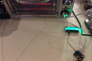
 Nick Sayer
 Jason
Jason
Nice looking project, RoGeorge. Looking forward to reading more updates.
It looks like we're using the same schematic capture program, too. :-)