Close
0%
0%

GPS Receiver for Nikon D3100 Cameras

An inexpensive and more accurate GPS receiver accessory for Nikon D3100 (and compatible) cameras.

Similar projects worth following
The goal of this project is to create a small device that will provide GPS data to a Nikon D3100 camera allowing it to tag photographs with location data.

The heart of this device is an easily obtained, small, inexpensive, GPS receiver package designed for use as part of a flight controller for radio controlled aircraft.

BACKGROUND

I bought my first digital SLR camera in January of 2013. I had thought about getting a digital SLR before then but they were not up to film standards or were way too expensive (almost $1,000 or more).

Just after Christmas a local store had a sale on a camera bundle that contained an entry level digital SLR made by Nikon. The camera in the bundle seemed a better choice than a similarly priced entry level Canon so I decided to buy it. I didn't think I would use the digital SLR camera that much as I had not taken many photographs with my 35mm SLR film camera in the last few years. I soon proved myself wrong on that count.

Since I bought the camera I have taken close to 6,000 pictures. I'm averaging around 200 photographs a month and I keep about 75% of them. I've been posting some of my photographs to Flickr and I add the locations for some of them to a map. That is when I realized I had a problem. I couldn't always remember exactly where I was when I took some of the pictures. I could keep a pen and paper on me but if I'm on the move and taking lots of photographs it would soon become burdensome to keep notes. I needed a better way to keep track of where I was when I take a photograph.

Nikon makes the GPS-1a attachment that I could use with my camera and it would solve the problem of keeping track of where I was when I take a photograph but the price on it is over $300. I looked around a bit more and found some other commercial GPS receivers available were more affordable at around $100 to $150 each. One was around the $60 mark but reviews of it mentioned some reliability issues.

During my research I found one DIY GPS receiver project online. It used a LEA-4S receiver module made by Ublox, which is one of their older products. The problem with it, and most of the commercial units, is the location data was stated as only being accurate to within 10m. When I'm on foot taking pictures a variation of 10m from my actual position can put me on the other side of a roadway, down the street by a few houses, or almost half a block away. I wanted something that could give me my location with better pecision and accuracy.

I looked for more information about the LEA-4S receiver module on the Ublox website to find out if it would be useful in my project, what was involved in using it, and the price for one. I discovered Ublox has a newer unit with the part designation of NEO-6M that has a claimed accuracy of 2.5m. At 4 times the accuracy of commercial units the NEO-6M would be good enough for my application. I soon found boards with a NEO-6M on them were readily available on eBay at a surprisingly low price. The DIY GPS project and the ready supply of inexpensive receiver boards on eBay inspired me to build my own GPS receiver attachment for my Nikon camera.


DETAILS

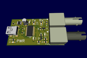
The heart of this GPS receiver attachment for a Nikon D3100 camera is a circuit board containing a Ublox NEO-6M. The boards are readily available on eBay at prices as low as $12 to $16 and include a passive antenna. The board sends out multiple NMEA data packets once per second at 9600 baud (its default rate). The catch here is the camera wants the data at 4800 baud. The addition of an 8-pin AVR micro-controller will allow the GPS data to be filtered and only the needed data will be passed to the camera at the rate it requires. The baud rate could be changed by a command to the NEO-6M device but if its configuration ever changed it might revert to sending data at 9600 baud and the camera would no longer see the location information.

I originally wanted to avoid using a micro-controller as I want to keep the current drain to a minimum. The micro-controller allows me to add a push button and an LED. They will let a user change some configuration options such as whether the unit is being used by someone walking around or if it is being used in a moving vehicle.

  • 1 × Ublox NEO-6M/NEO-7M/NEO-M8N receiver module and antenna
  • 1 × Interface PCB Contains microcontroller and sits between the camera and the GPS receiver
  • 1 × ATtiny45 AVR microcontroller from ATMEL Microprocessors, Microcontrollers, DSPs / ARM, RISC-Based Microcontrollers
  • 1 × MIC5205-3.3BM5 3.3V LDO voltage regulator
  • 1 × 220 ohm resistor

View all 19 components

  • Restructured source tree and test programs

    Kevin07/19/2017 at 03:34 0 comments

    I haven't worked on this project for a while due to a death in the family around the end of March. It put most of my project work on hold. I'm finally beginning to feel like getting back to work on some of the projects that have been on hold. I have only just recently started thinking about getting back to work on this project.

    Over the past three days I have restructured the source code tree for this project. I moved a number of files in to a separate directory and used them to make a library file. I also created a separate directory to hold various test programs. Some of the test programs use the new library file.

    In the past I ran tests by modifying the main program through #if statements. I now have separate programs to check control of the LED and to send serial data via bit banging and using the USI. I am now working on a test program that uses the USI to receive serial data from the GPS module. The serial receive routine is not yet working.

    I'm running the processor at a low clock rate to keep current consumption down. I parse the incoming NMEA formatted GPS data while it is being received to minimize the amount of RAM needed to store the data. I may not have enough execution cycles available to process the data on the fly. In the next few days I will check how much time it is taking to process the received serial data. If there isn't enough time to process the incoming data I may have to change the microcontroller to an ATtiny85. It has more RAM which would allow me to store the incoming GPS data which I can process in between the bursts of data from the GPS module.

  • Programming header design change

    Kevin09/29/2016 at 20:14 0 comments

    I recently discovered the Open Hardware Pogo-Pin Programmer project. It uses a header with a set of pogo pins and a single row of eight pads on a PCB in a space of about 400mils by 50mils to provide the connections necessary to program a part in-circuit. It saves a lot of board space compared to the typical approach of using a dual row header with 0.1" pin spacing. In addition to the amount of board space it saves it also eliminates the cost of the dual row header.

    I may adopt the use of a pogo pin based programmer connection in future projects. I am considering its use in this project but I don't think it will provide any real benefit so it may not be worth the effort to update the PCB.

  • Project update

    Kevin09/09/2016 at 20:53 0 comments

    It has been a while since my last log entry as I was working on other projects. During the past few weeks I set aside some time to work on the software needed for this project. I have been working on the routines needed to allow me to use the USI peripheral of the ATtiny45 to send and receive serial data. Three days ago I completed work on the sending routines and yesterday the receive routines started working.

    I worked on the transmit routines first so they could be used during the testing of the receive routines. The first message the transmit routines sent was none other than the usual string "Hello, world!". :) This was sent at 4800 baud once a second. Yesterday the transmit routine was showing me that a "$" character was being received. It is a very good indication that the receive routine is working properly.

    I already had the routines required to process the NMEA messages I'm expecting. I set up the main program to wait for the messages I need from the GPS receiver module before it would send any data. I use a Raspberry Pi to to monitor the serial data stream and I'm seeing characters being output once per second. Another good sign that I'm receiving the NMEA data from the GPS module and raising the flags that tell me when I have received both messages.

    The data transmitted after receiving the NMEA messages is not what I should be seeing. I need to do more tests to determine why I'm not seeing what I expect to see. Overall I'm pleased with the progress I've made on the software. I'm close to having the basic features implemented to have a fully working prototype.

  • Minor issues with the PCB layout

    Kevin05/21/2016 at 02:42 0 comments

    During the assembly of the PCB I noticed two minor problems that were just slight annoyances and not a show stopper.

    The first issue was an error in the silkscreen. During some previous revision of the PCB when I was moving parts around I had somehow swapped the component designations on the silkscreen for C1 and C4. This issue was an easy fix. I just back annotated the schematic and added a note about the change. The second issue was with the pin spacing for the 0.1uF capacitor. I thought I had ones with 0.1" pin spacing but the 50V rated one I grabbed when I assembled the board has a spacing of 0.2". I just had to give the capacitor leads a couple of extra bends to make the part fit.

    I have updated the PCB layout. First I rotated C2 and C3 180 degrees to shorten a couple of traces running to those parts then I adjusted the footprint for C4 to have a 0.2" spacing. These adjustments to the PCB may prove to be unnecessary as both of these parts may not be needed. I will be running some tests to determine whether they are needed once I have the main software running.

  • The PCBs have arrived

    Kevin05/20/2016 at 03:47 0 comments

    Three days ago I received the PCBs I had ordered from Elecrow for this project. I tried a dry fit of the USB connectors, switch, and pushbutton to make sure the footprints I created for those parts was correct. I was pleased to find all the parts fit. The next day I sat down to start assembling one of the boards.

    I'm not properly equipped for working with surface mount parts but I have previously assembled a small board that used all surface mount components. Unfortunately for me the voltage regulator is in a SOT23-5 package and was very difficult to solder. I ruined 3 regulators and one PCB and was about to give up but gave it one last try. I finally succeeded on my fourth and final attempt. It isn't up to my usual soldering standards but it was on the board and with no shorts between the pins.

    I soldered the rest of the components needed to provide 3.3V to the ATtiny45. I was pleased to read 3.3V on my meter when I applied power to the board and moved the slide switch to the on position. With that success in hand, I spent some time yesterday to finish installing the remaining parts on the board except for R1 and the LED. I plan to run some tests on the LED brightness versus current to make a final determination on the value for R1.

  • PCB is done, and search for a fab house

    Kevin05/03/2016 at 03:45 0 comments

    I have made adjustments to the footprint of the LED and the pushbutton. The updated footprints match up with the 3D models of the parts. With these last changes the work on the PCB design is done and the board is ready to be sent to a fab house.

    I have previously used OSHPark to make a PCB of mine and I wanted to use them again to make the board for this project. My board design has some plated through slots. I learned that OSHPark can't make boards that have plated through slots so I had to search for a different fab house. I settled on Elecrow. I had sent them an email asking if they can handle plated through slots and they said they can. I sent them the gerber files this past Friday and received a reply today that the boards have been put in to production.

    While I am waiting for the boards to arrive I can concentrate on the software needed for this project. The first version of the software will not include configuration options and some additional features I have planned. After the basic software is done I will work on the design of the enclosure. I have had most of the enclosure design in my head for some time. I just need to sit down and create the 3D model in Rhinoceros 3D. I know someone who has a 3D printer that can help me create the prototypes of the enclosure.

  • Work on this project is still ongoing

    Kevin03/08/2016 at 07:26 0 comments

    It has been several months since I last posted a project log. I have not abandoned this project. I finished work on another project that I have up on Hack A Day, then there was Christmas. Shortly after Christmas I was dealing with the illness and eventual loss (on February 18) of the beloved family cat. It all resulted in progress on this project being a bit slow during the past few months. I will post another log entry in the next day or so with an update on the status of this project.

  • Final(?) PCB, GPS tests/docs, and gallery updates

    Kevin10/21/2015 at 00:51 0 comments

    I've been working on some other projects so I'm a bit behind on updating the project log.

    I was looking at the PCB layout and felt I could reduce the width of the board another tenth of an inch. The board size won't make any difference in terms of the board cost but it will reduce the size of the enclosure which will reduce the amount of time and plastic required to 3D print it. The result was revision 14 of the PCB with a size of 1.4" x 1" (the same as the GPS receiver module). I thought it was as close to being done as I could get until I work on the enclosure for the boards but I was wrong.

    I've been trying to decide what to do with the GPS antenna when I put everything inside an enclosure that will be attached to the camera. I came up with the idea of mounting the antenna to the underside of the GPS receiver board as it has a nice flat surface. In order to do that I had to turn the GPS receiver board upside down which changed the order of the signals on the header that will plug in to the interface board. So, you guessed it, revision 15 of the PCB. I completed this latest revision four days ago. In addition to rewiring the header I added a ground plane to the bottom of the board. The only remaining changes I expect will be slight adjustments to the position of components close to the edges of the PCB, and maybe some footprints once the final components arrive in the mail.

    I have updated the gallery with the latest version of the PCB, updated the 3D model of the interface PCB, and added a 3D model showing a mock up of what will be inside the enclosure of the finished project.

    Due to work on other projects I haven't completed the testing of the three GPS receiver modules I have on hand. I also haven't finished reading through the total of 388 pages which make up the three documents for the Ublox GPS receiver modules. I'll get to these last tasks as soon as I get a few others items off my ToDo list.

  • GPS module test and evaluation

    Kevin10/02/2015 at 06:02 0 comments

    A couple of days ago I received the other two GPS receiver modules (NEO-7M and NEO-M8N) I had ordered. Today I took some time to do some initial tests of the two modules and check their performance. I also wanted to look at my original GPS module (NEO-6M) as it hasn't been able to get a satellite lock for several weeks.

    I wanted to use the u-center software from Ublox to test the modules but I needed a USB to serial adapter. I finally remembered I had a USB to serial console adapter cable for my Raspberry Pi. It uses a Prolific chip and it was exactly what I needed. The u-center software is Windows only and the only machine I have running Windows is my laptop. It was recently upgraded to Windows 10 and the Prolific driver would often report driver error on each boot. I took some time to research the driver problem and eventually sorted it out with the download of an older driver for my Prolific based device.

    Using the u-center software I was able to fix the configuration of my NEO-6M and it was able to get a lock on the satellites. I'm getting more comfortable with using the u-center software. It doesn't have much built-in documentation so it takes a bit of experimenting with it to make sense of its user interface. I started some preliminary tests on the 7M and M8N modules. Both came with a power indicator LED that is on all the time. I'll have to disable that it to avoid wasting power to light an LED that won't be seen in normal use.

    I performed some initial checks on the position data from the 7M and 8MN modules. Both units show variations in the position with the M8N typically showing less variation. It also was tracking 12 satellites where the other modules I have were only tracking 6. It will take a few days for me to run further tests and evaluations of the three modules I have. I will be looking at the amount of variation in position reports, checking how one of the configuration options affects the amount of variation, and also checking on the amount of current needed to power these modules. I will also be spending some time reading the hardware integration manual and the protocol specification for these GPS receiver modules.

  • Major PCB changes, parts, and 3D models

    Kevin09/27/2015 at 20:35 0 comments

    In my last log file I said I the PCB work is almost complete. Um... wrong! That was when I was on revision 4 of the PCB. I'm now on revision 11.

    About a week ago I received the right angle pushbuttons I had ordered. With the pushbutton in hand I created a 3D model of it for use with Kicad. When I added the model to the board I saw a problem. The switch was wider then expected so there was barely enough room for it. I swapped the pushbutton and slide switches (and voltage regulation parts), and widened the board to 1.75" to make a bit more room for the parts across the front of the PCB.

    I've searched for sync cables and found ones with a mini USB connector but none that used micro USB. This resulted in more PCB changes. The mini connector is wider than the micro so I would have had to widen the board by almost 0.1". By rotating P4 I was able to slide the mini USB in behind the pushbutton and avoided changing the size of the PCB. Having rotated P4 I decided to rotate IC1. I also changed the LED to a 3mm one as I felt the 5mm was too big compared to the 3.4mm diameter handle of the pushbutton right next to it. These two changes allowed me to shrink the PCB to 1.5" x 1" and it only has a single via.

    I have moved or redone all of the traces on the board several times but I think (I hope) that it is in a final state ready to be sent out to be manufactured. I have ordered all the remaining parts (USB mini connectors, slide switch, 3mm LEDs, and tantalum caps) needed for this project. Some of the parts were already in my parts bins but I will soon have enough parts to make more than one prototype. Once all the parts have arrived (it may be a month for some to arrive) I will do a final check of the PCB footprints before sending the board out to be made.

    I have updated the parts list for this project. One change was from a 5mm LED to a 3mm super bright one. It will allow me to reduce the current needed to drive the LED while still being bright enough to be visible when the device is used outdoors. I have made a note to see if can add a software option to offer variable brightness of the LED. When used indoors the user may want to reduce the LED brightness and further reducing current requirements.

    The last 3D models I need to make are for the top part of the camera and for the final enclosure. I need to check clearances between my devices enclosure and the cameras built-in flash unit as I don't want to interfere with the operation of the built-in flash. I still need to work out how to mount the GPS antenna in the enclosure and how I'm going to stabilize the end of the GPS module to minimize movement and vibration. Once the models are done the only remaining task is to finish the software. I will keep it simple at first by just having it calculate moving averages of the GPS data and handle the baud rate conversion.

View all 29 project logs

Enjoy this project?

Share

Discussions

Similar Projects

Does this project spark your interest?

Become a member to follow this project and never miss any updates