 Alex
AlexThis projects is about an small easy to use seven segment display. The disdplay is controlled by a 8-bit shift register. Rev2 and higher displays are chainable, so you can get multi segment display. Beside the Hardware there is also a Software part in this project. This software part is shared with a very similar project ( #µ7 ), wich is very similar (shrunken down version of tny7's rev1) but to to differnt to handle it as the same project.
Hardware
There is nothing special about the Hardware: on the ISP header you have access to three IOs of the micro controller. These are connected to shift-register, which drives the Leds.

The PCB should be small. So it can be used quick and easy. So I ended with this, after some hours of routing:
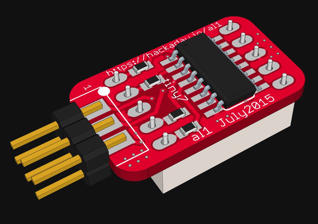
The used seven segment displays have a very clever pin out (this pin out is also very conmen, so nothing special): The common ground pin are in the middle. You can mount the display on both sides of the PCB and only the order of the segments changes. This could be reversed in software.
In the second revision two pin headers on both sides of the PCB got added. With these pin headers you can solder two (or more) PCBs together to get a two digit display. so you can create multiple digit displays.
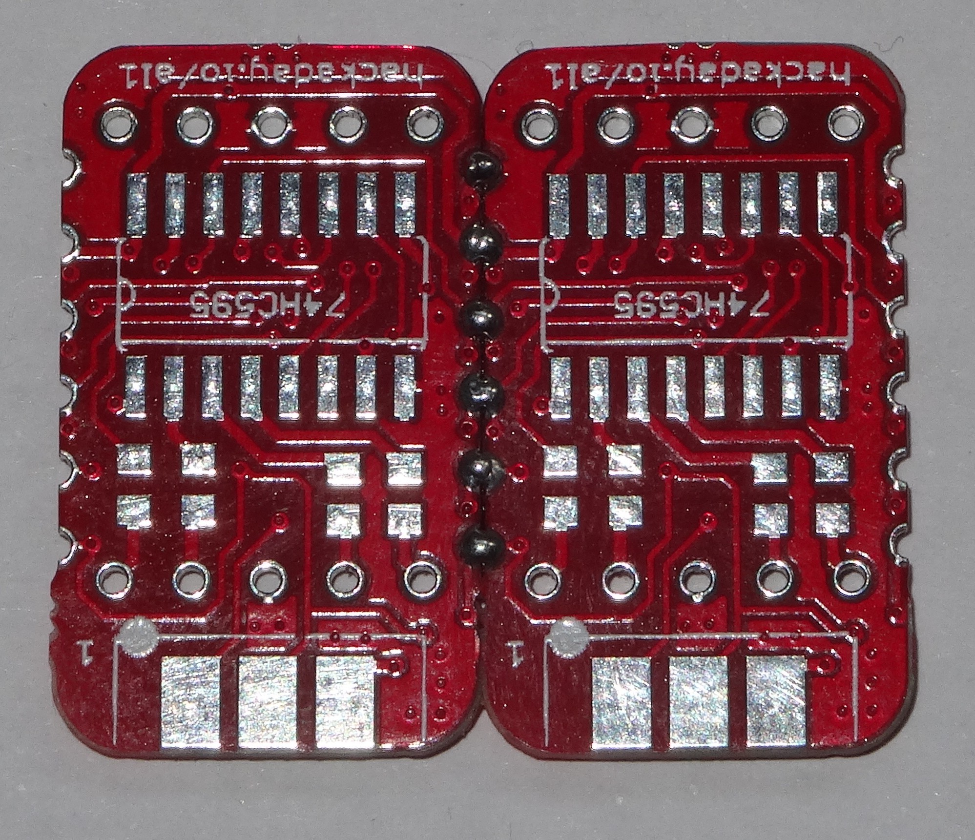
In revision 2.1 there is beside some minor changed an SMD solder jumper added. with this solder Jumper you can connect the common pins of the display to GND or Vcc. So common anode or common cathode display can be used. The library is also updated to use this option.
Hardware files (eagle) are availible in the bitbucked reposetory.
Software
There is a working Arduino library available (see Bitbucket). With this you can control one or more displays. The plain C library is not ready yet.
Using the Arduino Library
To use the Arduino Library you have to include it first. Additionally you have to create an tiny7 object:
#include <tiny7.h>
tiny7 myTiny7;
In your setup you have to use the function .begin() this is the prototype of the function:void begin(char inLength=1, // length of chain
char inInvert=0, // display orientation
char commonPin= T7_CC, // common cathode/anode
char inSDO=127, // MOSI pin
char inSCK=127, // SCK pin
char inLatch=127); // MISO pin (used for the latch)
None of the Parameters are needed if using only one tiny7, normal display mount, normal Arduino and common cathode display. So is could look like: myTiny7.begin(); //setup for one tiny7The other parameters of begin can be used to use for additional configuration if needed.
Now you can use your display by using the .print() function. For example like this:
myTiny7.print("H");There is also an .printf() Function availible. This is very usefull for display values with an unit on bigger displays. For example you can do this: 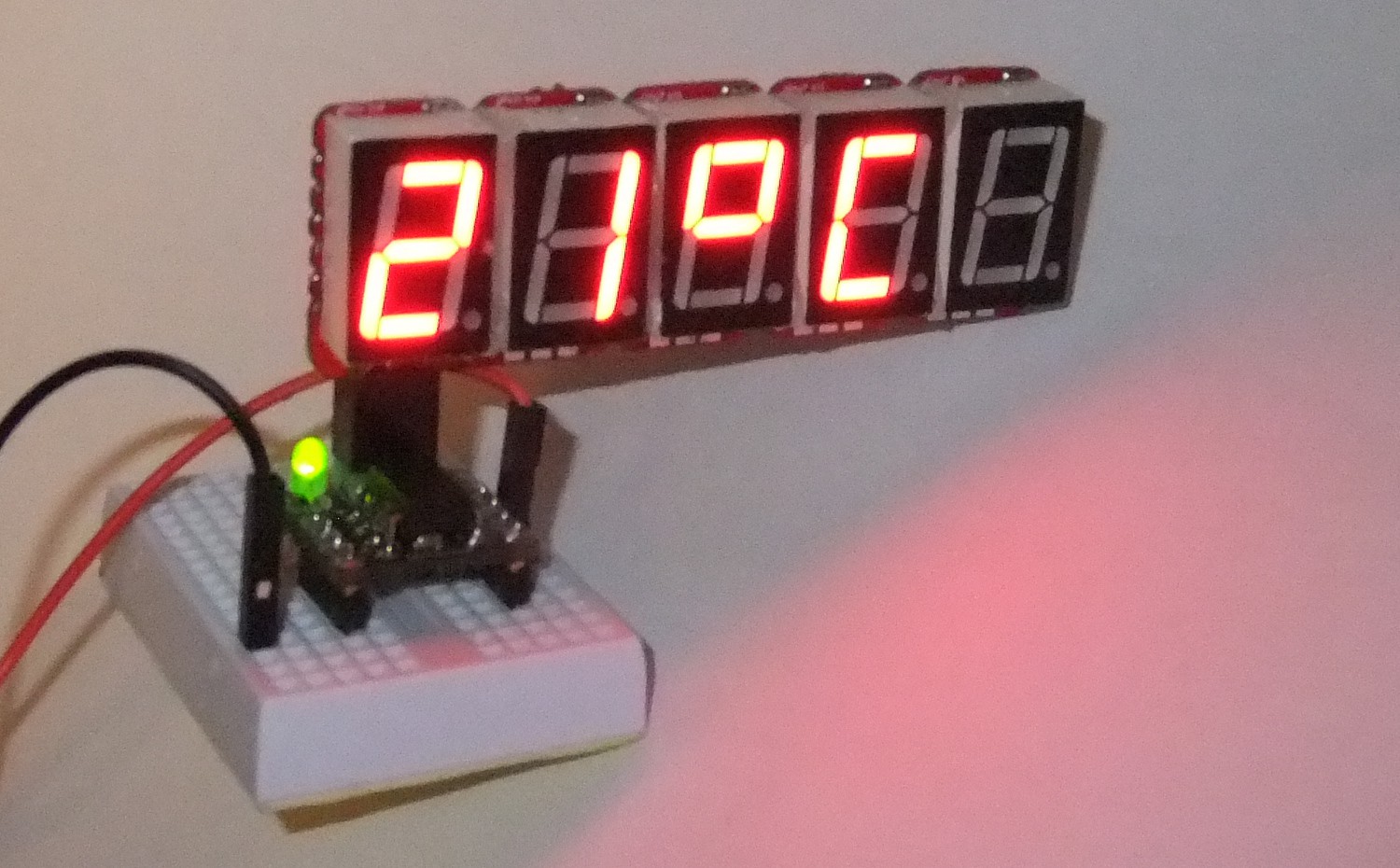 with this function call:
myTiny7.printf("%d`C",21);More examples can be found in the library!
Tested devices
I did test test the library and the tiny7 with the following devices:
- Arduino Nano with ATmega 328p
- ESP8266 development board ( #ESP8266 (ESP-07/12) Dev Board )
- ATtiny 85 ( used as Trinket)
- Arduino Mega2560 with ATmega 2560
It should work on all board which are using the Arduino IDE. The pins used by the tiny7 library can be changed in the .begin() function.
Used Tools and Software
Cadsoft, Egale 7.2 Freeware for circuit an PCB
Jerome Lamy, egleUp for the 3D images (freeware)
ImageMagick Studio LLC, ImageMagick used by eagleUp (open source, Apache 2.0)
Trimble Navigation, SktechUp Make for the 3D images
Arduino IDE
Notepad++ v6.4.2
GIMP 2.8
Credits
First I would like to thank to everyone who write comment, following this project or gave a skull. Specially @Stefan Lochbrunner who had the idea of dais chain multiple displays.
I would also thanks @WooDWorkeR. With him I did have an inspired taslk about how to mechanical strengthen the connection between multiple displays. I am still thinking about which one would be the best. Hot Glue? Foame
tape? soldering massive wires on it? or maybe some other? I do not know
yet., but I like hot glue.