 GuyisIT
The 10,000ft view of the project is this: Using a python script running on a Raspberry Pi, take picture(s) and print them onto photo paper.
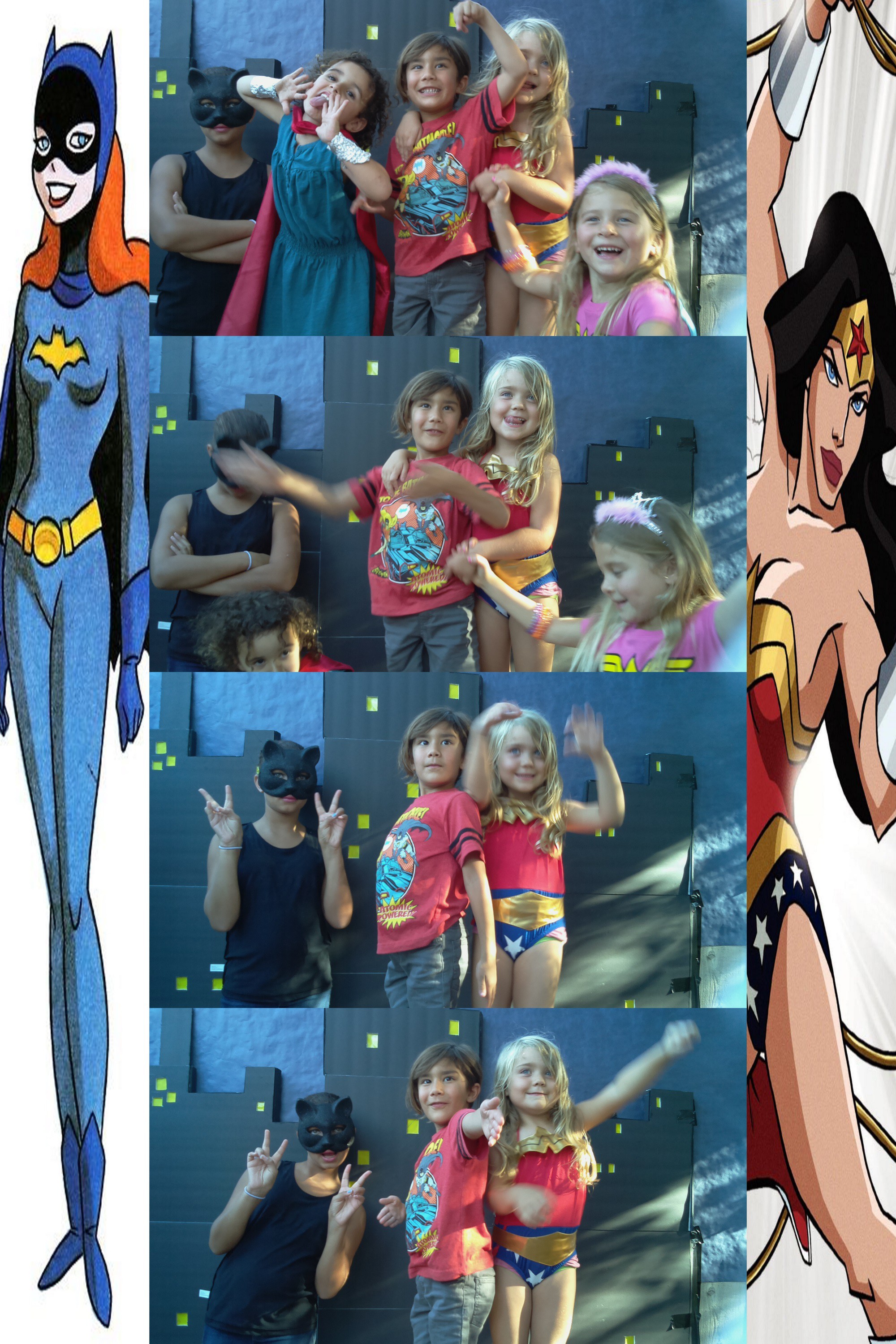
1-100ft view: I'm using a hacked together python script that uses the GPIO pins on the RasPi to read button presses and take pictures. Each button corresponds with a different 'style' of photo (one, 2x2, 4x1). This is then post-processed and sent to a Canon SELPY C910, which prints a 4x6 photo.
During the post processing, images are combined/ rotated where needed, and a watermark is added. A header/footer image is also added, to bring the total dimensions to a 3:2 aspect ratio (to match the photo paper.)


 Above is the jar lid ring being glued in place, and below is the finished product, with an unaltered lid ring and insert next to it for comparison.
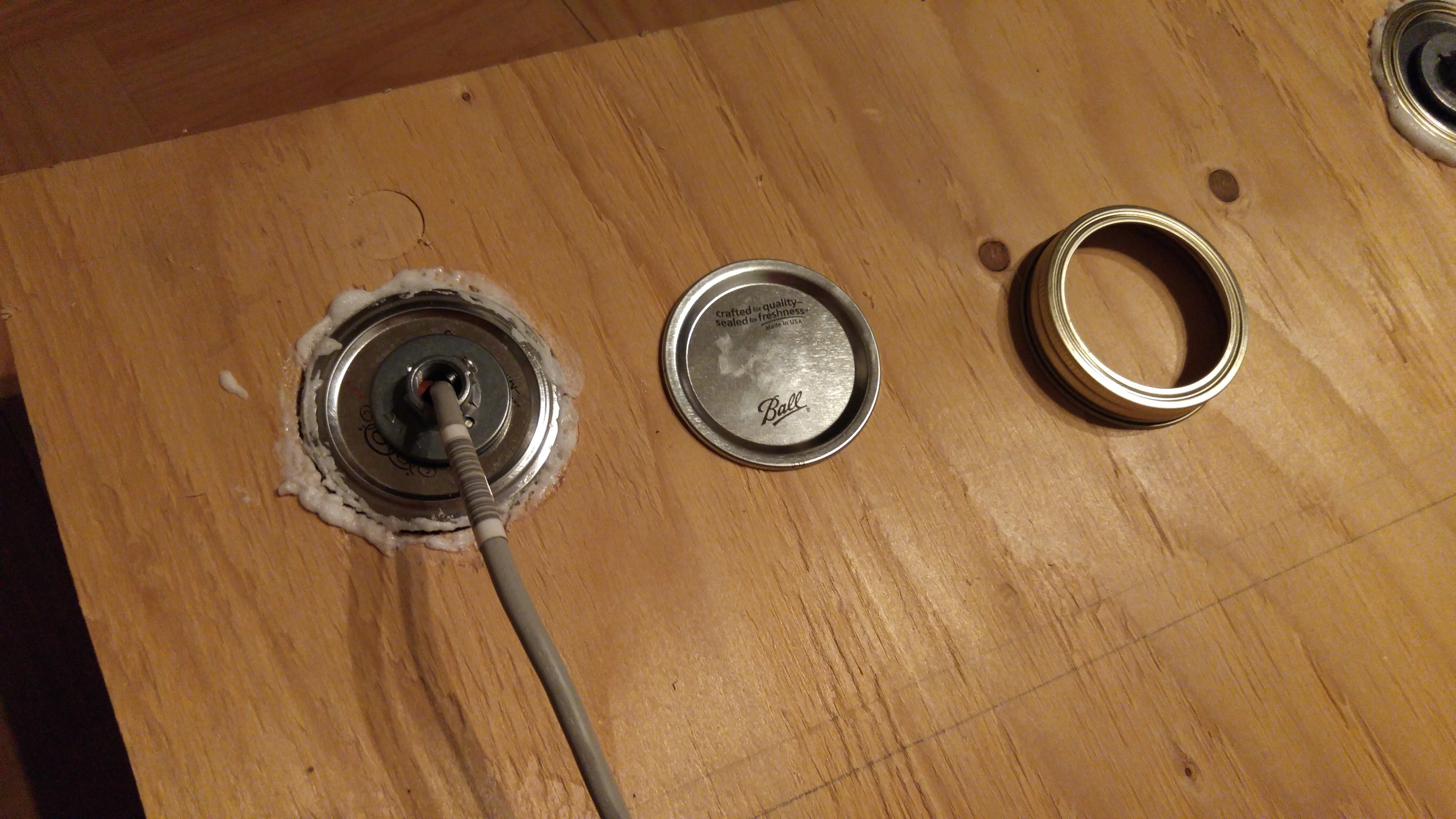


 Leonard
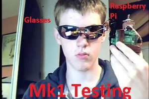
 danielmcgraw
 Warren
 nitr1c