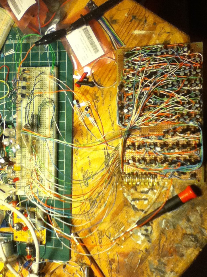
I finished the instruction decoding logic. here it is:
![]()
![]()
it's not quite done in these photos, but the finished version looks almost exactly the same.
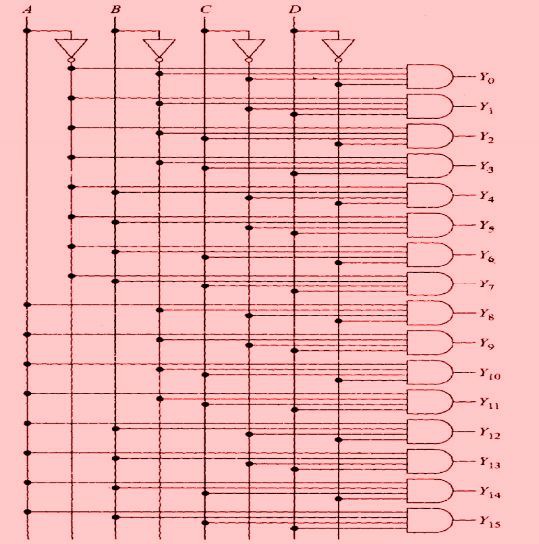
the instruction decoding logic's (IDL) job is to change a binary instruction into the appropriate control bits. I.e. if the next command is xxxx1000 (load @ register) I need to change that into a high on the load pin of the RAM. this means that the IDL is essentially a 1:16 multiplexer with the input held high. or this:
![]()
you may remember this circuit. I have already built one and it didn't work great, you can read about adventure here: (http://hackaday.io/project/665-4-bit-computer-built-from-discrete-transistors/log/7684-maker-faire-and-project-update)
basically the problem that I had previously was that I built the four input AND gates like this:
![]()
the above design reduces the number of transistors but ends up with sloppy logic levels. I ended up needing integrated circuits to fix this problem last time (see link above). this time I wanted to avoid ICs so I redesigned the four input and gates so that they now look like this:
![]()
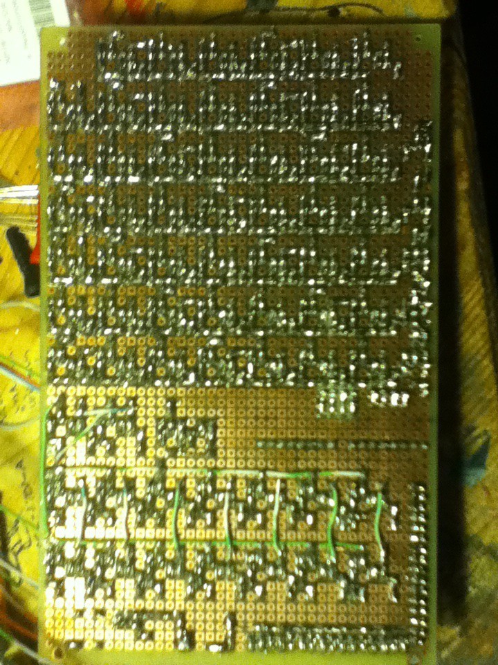
more transistors, but it works waaaaaaay better. astute observers will notice that the above design is just 3 two input AND gates. this method takes 50% more transistors but it is worth it in my opinion. after I had the AND gates built it was basically just a whole lot of boring wiring. and then I tested it and it didn't work uh-oh. the first thing I did was mess around with some resistor values on the inverters, and then it almost worked. after much hunting I determined that the input to one of the inverters was higher than it should be almost all the time, and seemed to be crossed with another input. it couldn't be a dead short between two pads on the board because the resistance between the inputs on the two inverters was extremely high. I figured it must be a solder flake bridging to pads, but after much inspection and cleaning the bug persisted. for reference here is the solder side of the board I'm working on:
![]()
when I was laying out the board I drew some pencil lines on the top so that I would know where to build things and to make sure that each of the AND gates was the same size. it turns out graphite is conductive (kinda). yay! basically what happened was that a pencil line had bridged two pads, but since graphite has very high resistance my continuity tester did not see it as a short. after cleaning off the graphite everything worked as it should. moral of the story is: use some sort of non-conductive marking system to layout perfboard.
whats next?
hypothetically the IDL is the last piece of logic to build. I should be able to connect all the pieces and have a working processor. however in real life it will probably be more complex than that. but that's the next step: start trying to get all the pieces playing together.
other stuff:
this project got an article written about it on hackaday.com. you can read the article here: http://hackaday.com/2014/11/22/a-4-bit-computer-from-discrete-transistors/
I imagine that's where most of you would have heard about this project, so thanks for all the views/skulls/follows.
 zaphod
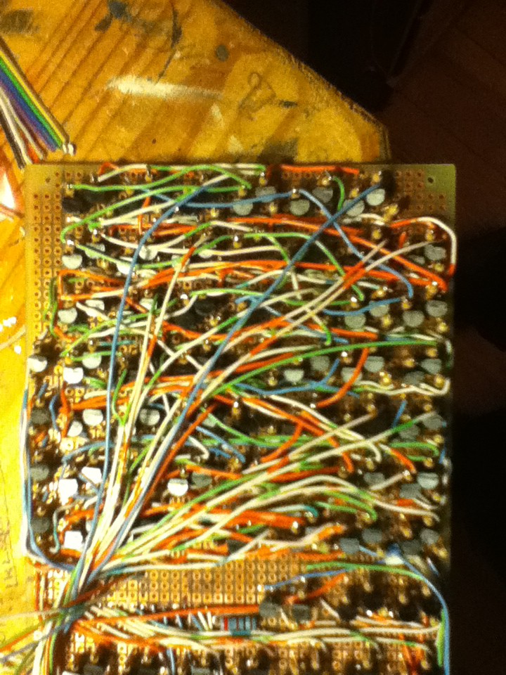


Discussions
Become a Hackaday.io Member
Create an account to leave a comment. Already have an account? Log In.