 zaphod
I'm back!
last weekend I got around to soldering the ~120 transistors that make up most of the program counter.
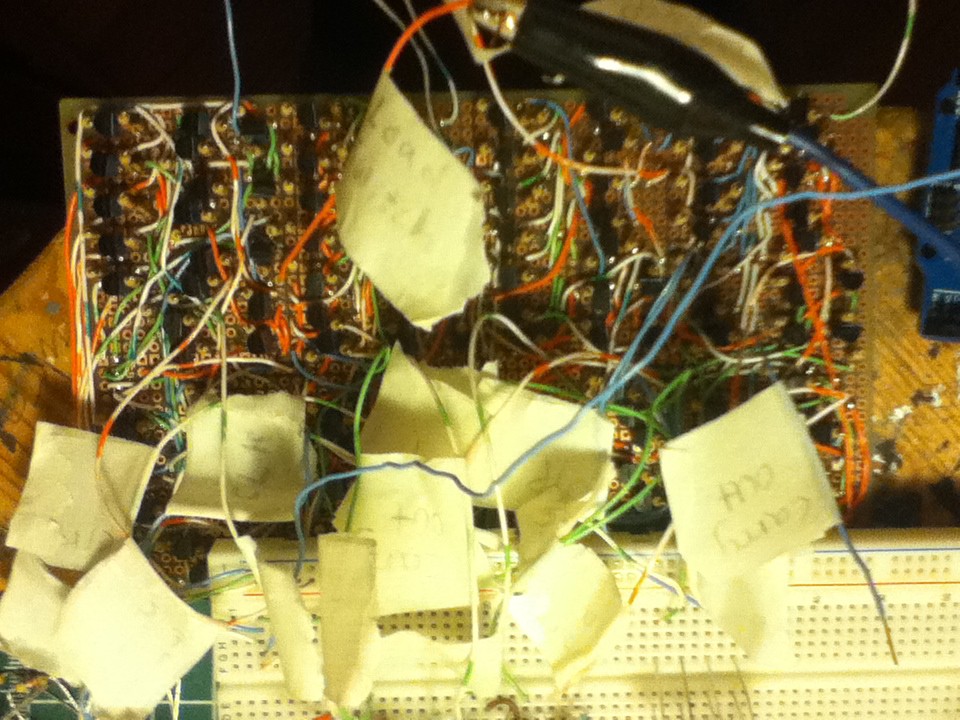
as of right now I think this is the most densely packed board I have made for the computer (and possibly ever).
here's the schematic:
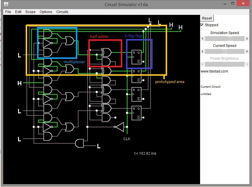
and here's how the board is divided up:
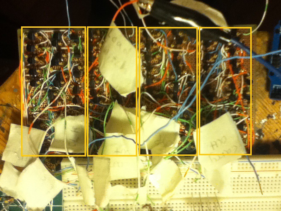
the yellow boxes in the photo correspond to the yellow box in the schematic.
some astute viewers may have noticed the AND gate and the inverter in the above schematic. these are not on the above board because I ran out of space, hence the breadboard in the below picture:
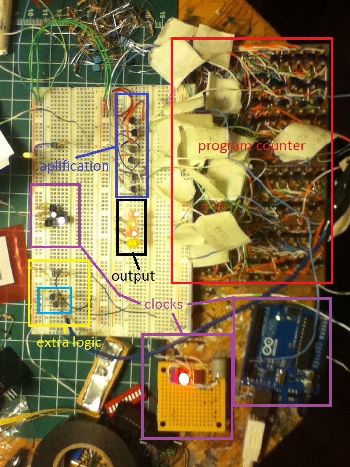
the red is the majority of the logic for the program counter. the yellow box denotes the extra logic. the blue box within the yellow box is the missing AND gate, the other transistor is the NOT gate.
the black box is the output. the output is a four bit binary count:
0000
0001
0010
0011
0100
etc...
it is currently represented by LEDs but will eventually be fed into the ROM as an address value.
the dark blue box is some amplification. each section of the program counter is essentially a half-adder, so the way that each section effects the next section is by sending a 'carry' bit to the next half-adder down the chain. it turns out that when I implemented this the carry bit was too weak to be read as a 1 by the next section of the circuit. because of this it is necessary to amplify each of the 'carry out' lines all the way down the chain.
the final boxes are clocks. the presence of three boxes marked 'clock' begs the question, why are there three clk sources? the answer is that I've had some trouble finding a good source. the first potential source is the Arduino.
pros of the Arduino as a clock:
-I can accurately say the processor has a clock speed of 'X'
-I can easily change the clock speed, to try to find the fastest speed that the processor will run at.
cons:
-it's an entire Arduino (!!!)
so I will probably not use the Arduino as a clock source, because it is overkill. I could potentially integrate the clock output onto the ATmega that is acting as RAM, however, this would probably cause more timing problems than it would solve.
the second second potential clock source is the 555 timer in astable mode.
pros of the 555 timer:
-easy to change clock speed
-simple
cons:
-I can't find the exact clock speed without some math, and even then it's debatable as it relies on component tolerances, and the various parasitic forces at play within the circuit
-it's still a chip, and this is a discrete transistor computer.
the third potential clock source is this circuit:
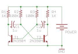
i'm not sure what it's called but it does seem to generate an oscillating waveform.
pros:
-made out of discrete components (yay)
cons:
-I can't calculate clock speed, (it requires math that I don't yet know how to do)
-it doesn't seem to play nice with my program counter. I have no idea why this circuit doesn't work with what I have built. my hypothesis is that the square(ish) wave that it outputs is too noisy, and is causing some kind of incorrect count. this is just a hypothesis, and to test it I would need an oscilloscope, which I don't have access to.
as of now I don't have any idea of which clock I will use, however right now I would give the edge to the 555 timer. if you have any suggestions, about discrete transistor oscillators, or why the above circuit doesn't work feel free to comment.
Discussions
Become a Hackaday.io Member
Create an account to leave a comment. Already have an account? Log In.
Nice log, I love to see progress here. Seems like there is still long way to go.
Are you sure? yes | no
Are you sure? yes | no