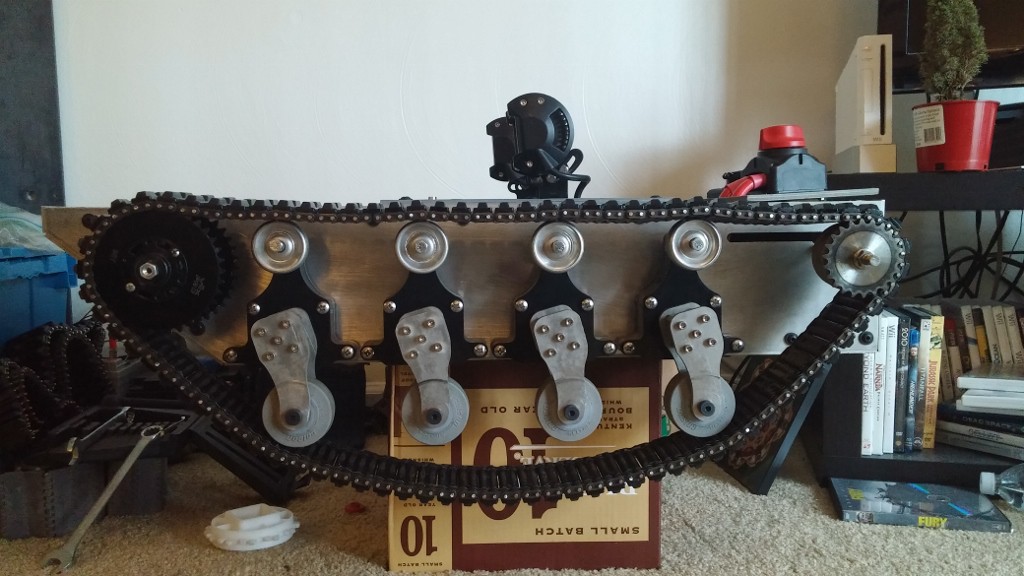
Close
0%
0%

Expandable Ruggedized Robotic Platform

Robotic platform designed to operated in harsh conditions experienced in outdoor environments. Modular with easy to replace components.

Similar projects worth following
The goal of this project is to create a easily expandable robotic platform capable of operating outdoors in all conditions. Tracks provide superior traction and ground pressure while FRC Mini-CIM motors provide 700 in-lb of torque, sufficient to move the robot over rough terrain and carry significant payloads.

Frame is composed of aluminium 8020 extrusions with 1/8" aluminium skin bolted into the 8020. Suspension system is composed of rotation plates of aluminium and stainless steel. Work on both robotic platform and universal controller is ongoing.

Chassis:

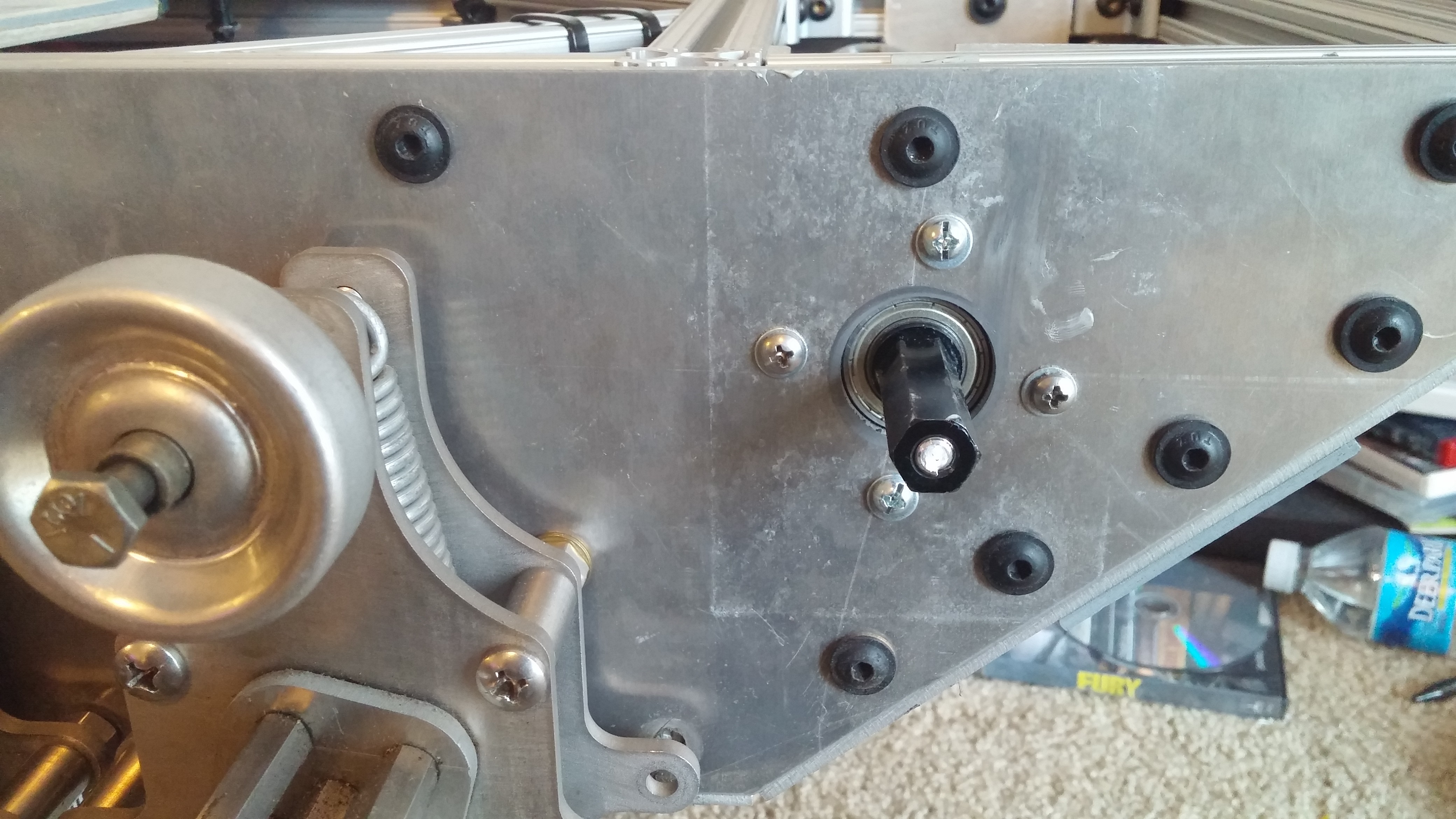
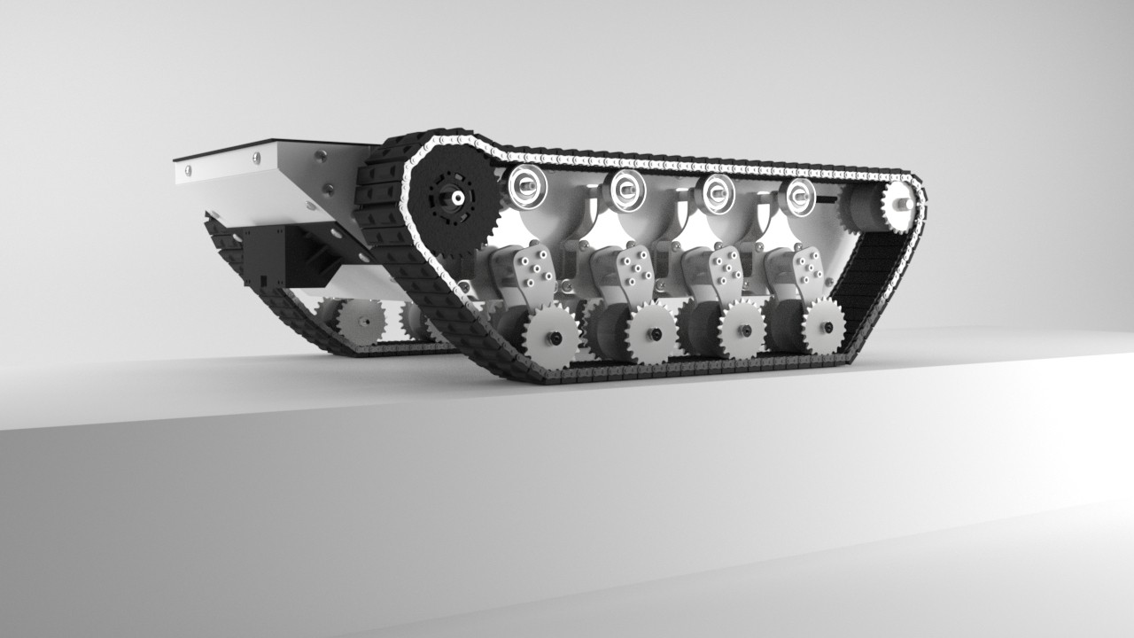
The frame of the robot is composed of aluminium 8020 bolted together using a combination of off-the-shelf and custom brackets. Onto this frame waterjet cut 1/8" aluminium panels are bolted, which creates a strong but lightweight and easy to repair chassis.

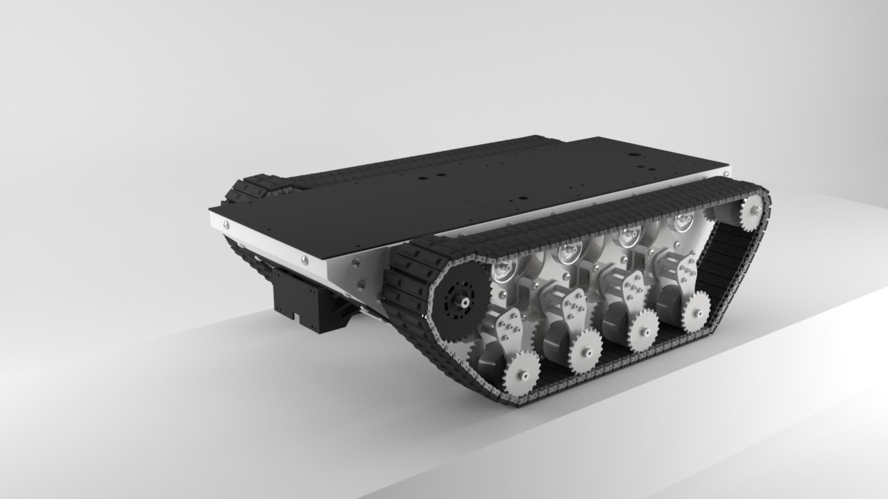
The entire frame was model in Autodesk Inventor to ensure a proper fit. (3DS Max was used for the renderings)
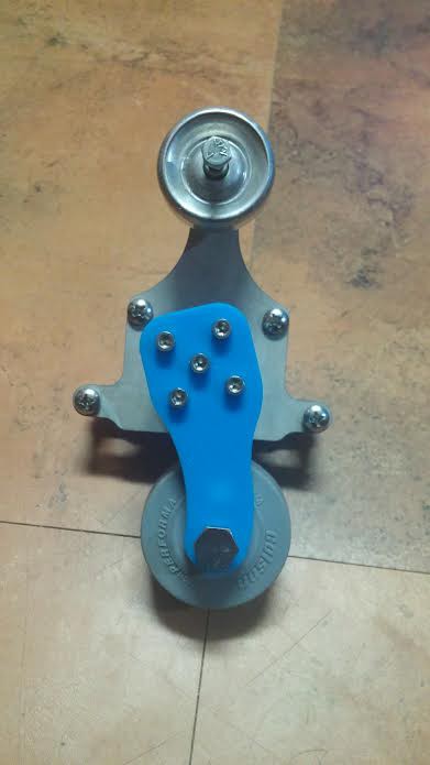
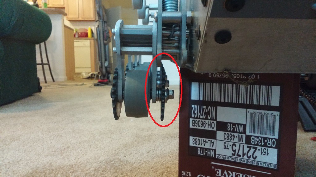
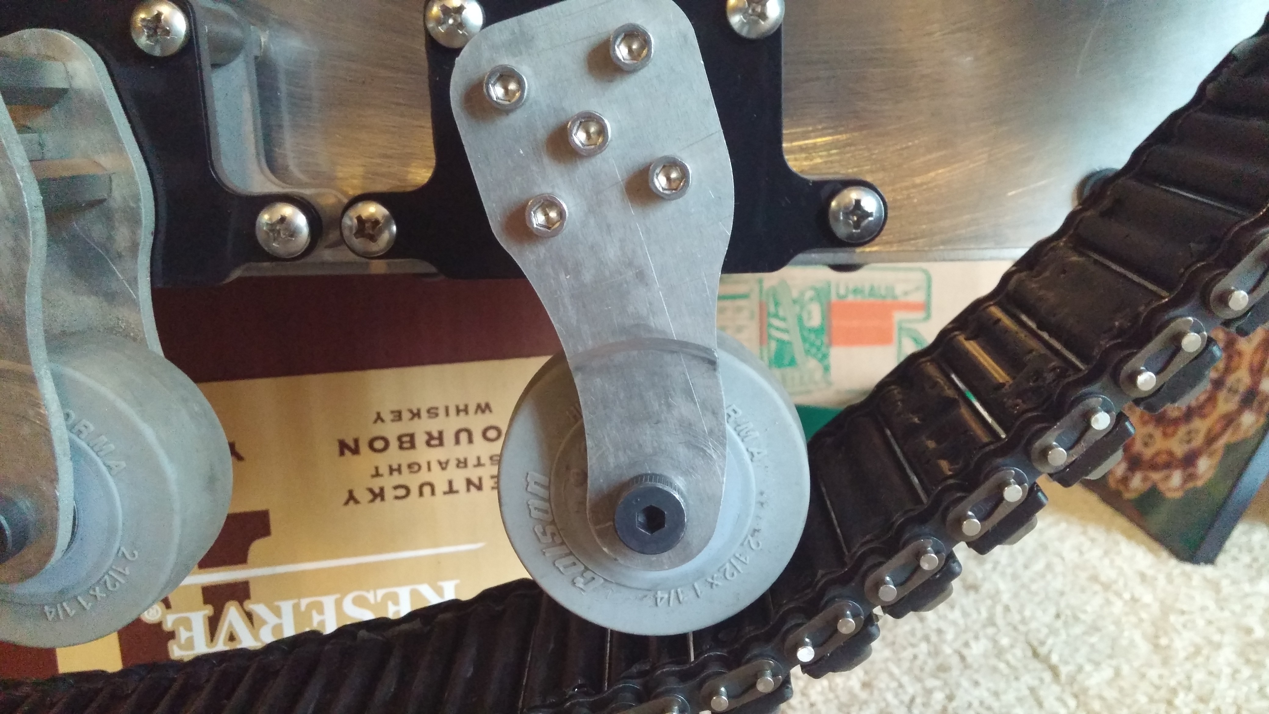


Suspension System:

The suspension system is composed of cut aluminium and stainless steel plates which pivot on shoulder screws. An early simulation can be found here: https://youtu.be/ClKLkGF4tBQ

A single spring provides the force which returns the wheel carriage to the upright position.


All pieces were first prototyped out of acrylic to act as a "proof of concept" and to ensure proper tolerances.

Eventually I will have a video to show the suspension in action.
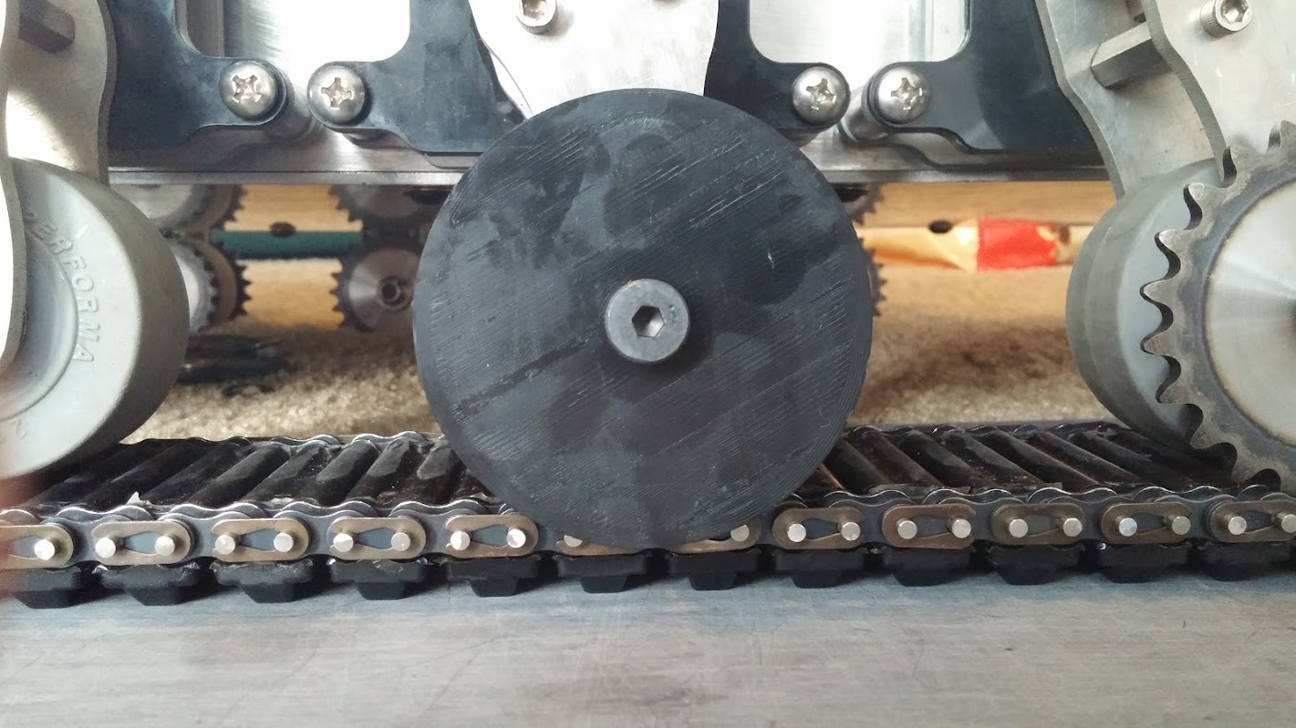

Drive Train:

In order to simplify the overall design, a self-contained off-the-shelf drive train was selected created for FRC robotics competitions. A mini-CIM and versa-planetary gearbox along with talon speed controller.

While adapting the motor to work with the gearbox reduced the key-way significantly, it was worth it just to make everything much cleaner and easier. Plus the mini-CIM motors are sealed which is a plus. The combination provides 700 in-lbs of torque.

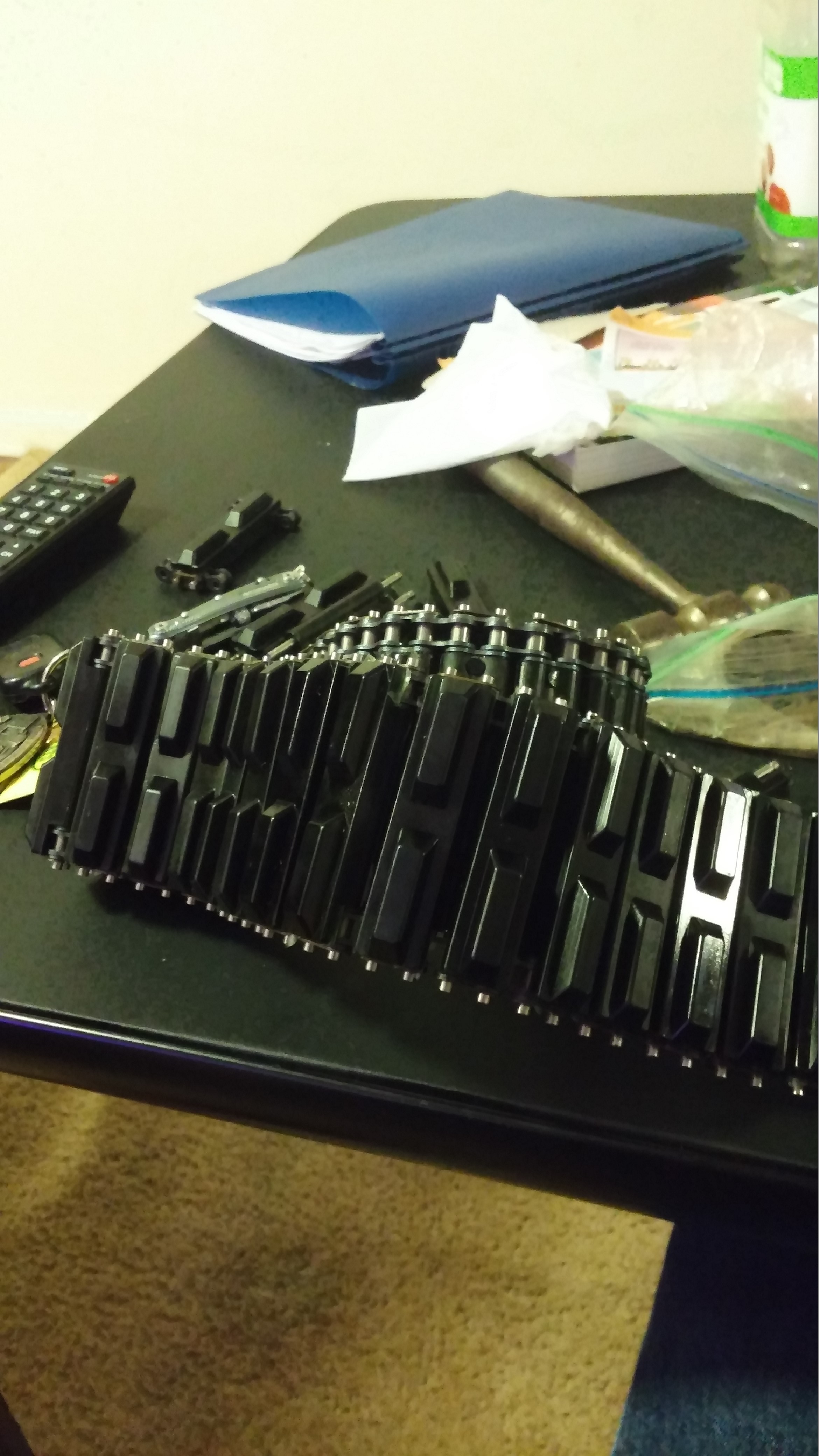
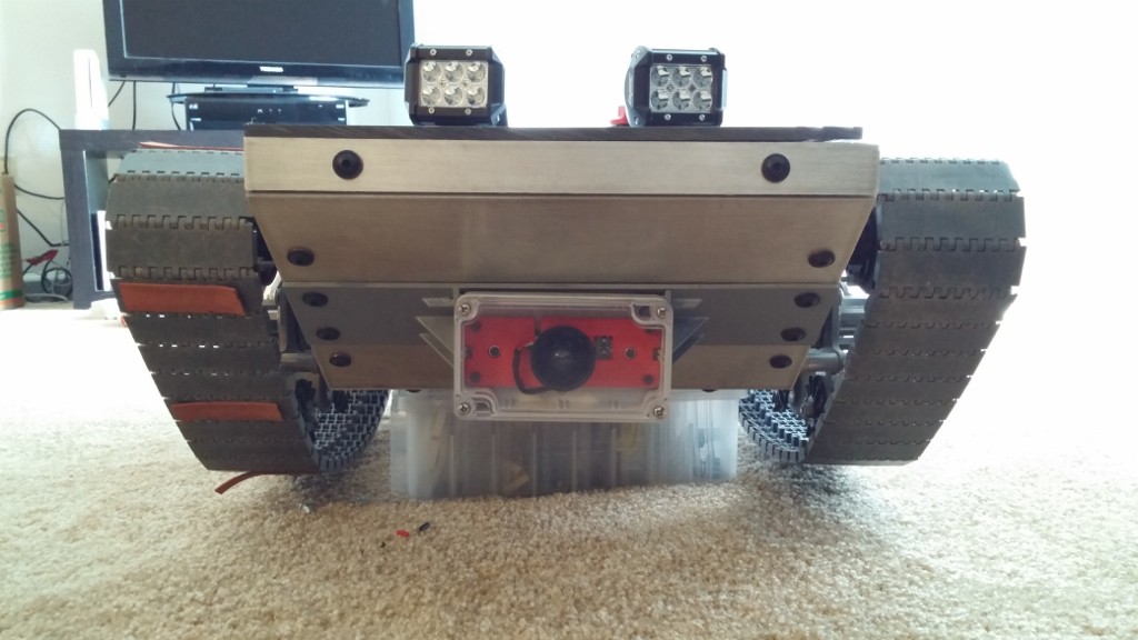
The treads are made from delrin, and are industrial conveyor belts.

A custom square bore cog interfaces with the belts, so a 3D printed adapter is used with a standard 1/2 Hex shaft and off-the-shelf FRC wheel hubs to get the torque to the treads. 3D printed parts are also used to help keep the belts aligned with the wheels and maintain proper tension.
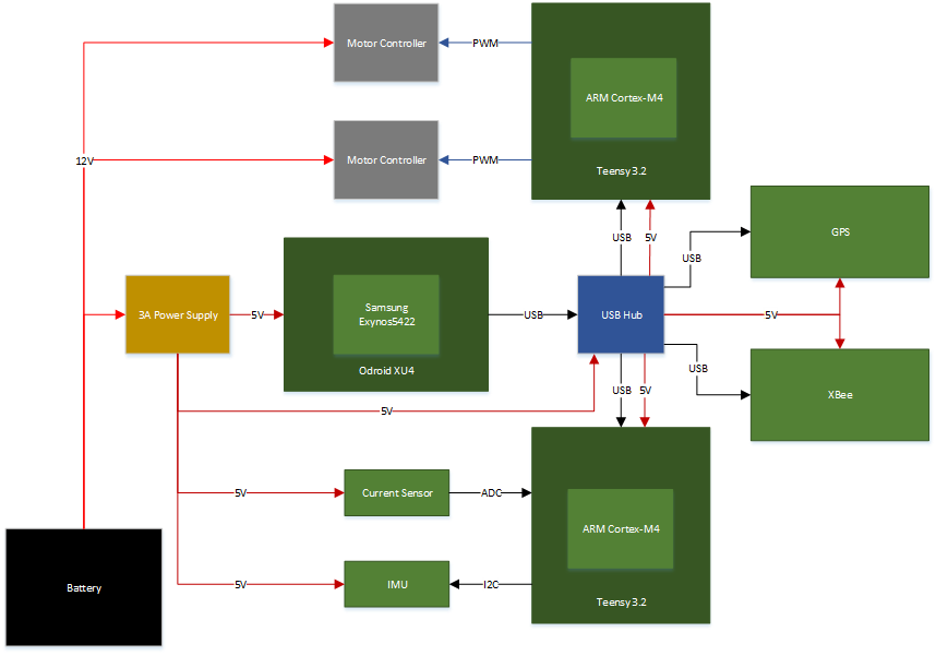

Electronics:

Main controller is a Beaglebone Black. It controls the motors, handles motion planning and remote controlled operations.

A custom cape interfaces the 3.3V board with the 5V external peripherals and adds an Real TIme Clock (DS1307) an Xbee radio socket.

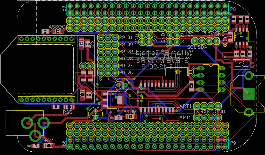
The main power source for system comes from a 26 Amp-Hour lead acid battery and the motors are controlled by two FRC Jaguar motor controllers control by PWM.
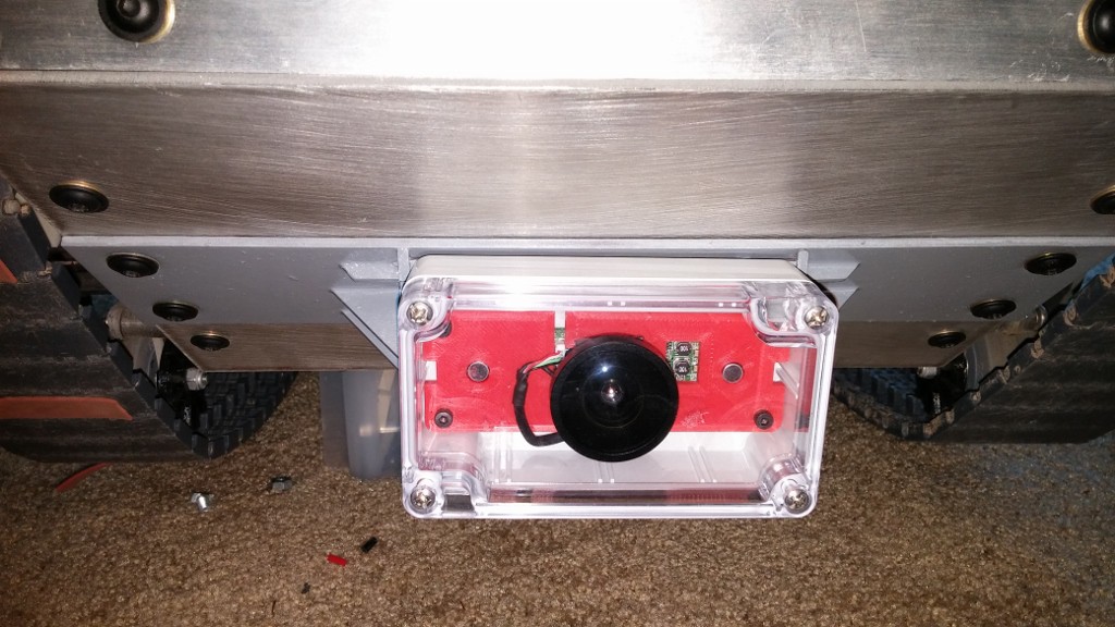

Water Proofing

In order to actually be a usable, the robot must be able to work in wet conditions. While sealing the entire chassis is an option, it would make replacing panels difficult. Instead all electronics will be enclosed inside of IP67 or higher enclosures and interconnected with waterproof circular connectors. This both makes the electronics much more durable, and easier to replace or upgrade.


More specific details and updates will be in the project logs.

  • 1 × Beaglebone Black
  • 1 × Custom Cape
  • 2 × jaguar Motor Controller
  • 2 × Mini-CIM
  • 2 × Versa-Planetary Gearbox

  • Minor Update

    williamg4203/24/2016 at 15:40 0 comments

    In order to reduce friction and help with spacing, I ordered and installed oil impregnated bronze bushings for the sprockets, however it has not fixed the problem. My current working theory is the sprocket's teeth are not releasing from the chain and as a result are getting jammed in the chain links and pulled backwards, royally messing up the drive train and preventing forward movement.

    The current fix (just to get the friggin robot to move) is to discard the sprockets (for now, I think they are the best solution, but sometimes excellence is the enemy of good enough) and use some oversized 3" washers and the spacers previously purchased to keep the chain captive. I've run a simulation and with two washers on each side, the maximum deflection due to a 100 lb-force load on the area where the chain is contained is .01" maximum.

    Which is good enough. I also managed to bend both the original rod, and the new one I ordered with the bearings.

    Here is the mockup of the 3" washer on the system.

    And the washers came in fairly quick, so I've started working on installation. I also laser cut acetal copolymer, mainly because it looked cool and would help protect the aluminium from getting scratched.

    That is all for now! Hopefully I will have time this weekend to replace the bad output shaft on the left gearbox, and finish attaching the washers to the wheels, so I can get this robot rolling again!

  • Updates! Mechanical, software, and more!

    williamg4203/05/2016 at 16:51 0 comments

    Sorry for the long bought of silence, between school and a mishap with the ordering department, I have just within the last week got all the mechanical bits required to mount the new treads. However there is still some mechanical bits that need to be finalized and some bugs to hammered out.

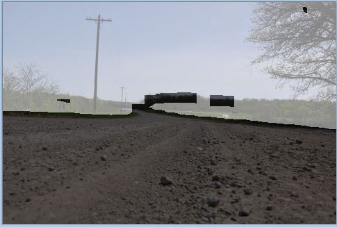
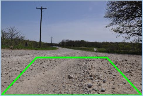
    (sorry for the potato quality photos, took these on my phone before I left for spring break)

    First on the list:
    Sprockets on the wheel modules are creating some problems. Basically in order for the suspension system to work, the sprocket on the inside needs to be offset enough to avoid hitting parts of the suspension system

    As you can see the sprockets had to be offset to avoid hitting the steel plate. However, The sprocket on the outside of the system has no washer now, and grinds the aluminium, and locks up.

    You can see the marks on the wheel module above.

    Basically I just need to play with spacing and spacer so that the sprockets can rotate without grinding but still be captive and rigid enough so the treads don't slide off. I'm thinking that laser cut acetal resin washers/spacers is probably the best bet. I've already used that technique to help reduce friction on the suspension system, as you can above and below.

    The acetal resin dramatically helped with friction and binding, and combined with new oil-impregnated washer I hope will provide a longer service life before the washers wear out. I think doing something similar to the outside of the wheel module, combined with oil impregnated washers, would help the spacing of the sprockets as well as prevent the sprockets from binding and locking up the drive train.

    Second:

    I need to replace some parts of the drive train. Sadly, while taking apart drive train, I broke a standoff.

    Opps. So the output of the drive shaft needs to be replaced. Fairly easy to do, just a bit of a pain as the whole front of the robot needs to be taken off to get the motor and gearbox out.

    However overall I am very happy with the new tracks and cannot wait to get the system moving. And every single part I need to get the system function arrived in the mail before spring break. So hopefully I can get the platform moving before the 19th.

    Software:


    I've continued working on the monocular camera obstacle avoidance and I would say that overall it is going pretty well. Basically the last big challenge is getting rid of the latency due to the video frame buffer in OpenCv. Sadly the OpenCV video capture property CV_CAP_PROP_BUFFERSIZE isn't working with the Logitech C920 on the Odroid. Therefore another solution needs to be found to ensure the video frame being processed is as close to real time as possible.

    But as you can see the algorithm works fantastically well on road surfaces


    And does a great job on finding obstacles in an unknown enviroment. Sadly no screenshots of this yet, but hopefully soon.


    The next big step is to implement memory, and have the system save the histograms from previous frames and use those histograms to find obstacles in the current frame. This will remove the strong assumption that the area in the reference area (green box above) is free from obstacles and would allow the user to "train" the robot by manually driving the robot.


  • Some slight mechanical misfit

    williamg4201/21/2016 at 16:55 0 comments

    So finished assembling the new treads and test fitted them on the chassis.

    It looks good! Downside is my CAD model was a little bit off, so the spacers spacing the sprockets so they interface with the chain on the boogie wheels is a little bit off (looks like an 1/8 of an inch or so on each side). Opps. But my 3D printer has been fixed and the Taulman Bridge Nylon has arrived, so I will print some spacers. They will either be a temporary measure to ensure the new spaces fit or as a permanent solution if they work well (really depends on how well they hold up).

    That is all for now!

  • New treads have arrived!

    williamg4201/19/2016 at 15:51 0 comments

    Just a quick update, with the big news being the new improved treads have arrived and I have started to assemble them.

    I am very impressed with the quality and cannot wait to mount them on the chassis. In addition I have continued to work on the software for the Cortex M4 (Teensy 3.2) to control the motors given a velocity and angle message sent over USB. Hopefully I can finish that up today. Now that I am back at college, I can once again have access to the chassis.

    That is all for know!

  • Mechanical and Electrical Improvements (12-15-2015)

    williamg4212/15/2015 at 17:52 0 comments

    Sorry for the delay in updating this project, but it's the final stretch in the semester so I have not had a lot of free time. However I have had time to finalize several electrical and mechanical improvements, order parts, and render some new models to show the changes!

    The biggest mechanical change is moving away from industrial conveyor belts (which work well on flat surfaces but are too slick to grip well) and use jupdyke's Modular Continuous Track System! I'm excited to get my hands on the new tracks and see how well they perform. Since I can use steel sprockets and have more control over the length of the tracks, they should help prevent the system from throwing tracks as often as it is now. Also, I should be able to go up wet hills!

    I've also finalized the design for the new camera mount and laser-cut an abs prototype.

    New renderings with improved tracks, sprockets, and the new camera mount:

    On the electronics front I've installed OpenCV with OpenCL, OpenGL, TBB, and as many other optimizations as possible on the Odroid XU4, and have the obstacle detection algorithm running at 10 FPS. Taking a lesson from ROS and the embedded systems class here, I've tried break the system into smaller parts to make programming and debugging as easy as possible and have them communicate with each other with standard messages. Therefore, I have the Odroid XU4 doing the image processing and sending messages over USB to Teensy 3.2s which interface with the sensors and motor controllers. This way, I can program and test the motion control and planning, obstacle detection, and sensors interdependently.

    Updated Block Diagram:

    That is all for now.

    -William

  • Obstacle Detection and Avoidance

    williamg4210/31/2015 at 16:46 0 comments

    Examples

    Original

    Processed (White is impassable terrain)

    Obstacle Detection:

    based on and taken from:
    Ulrich, I. 2000. Appearance-Based Obstacle Detection with Monocular Color Vision. In Proceedings of the AAAI National Conference on Artificial Intelligence.

    Theory:

    The basic algorithm utilizes histograms and a "safe" area to detect impassable terrain in the environment. It is assumed the area directly in front of the robot is clear of obstacles, and can be used as a reference. A histogram of this safe region is generated. The more advance alogrithm stores histograms from past travel, and uses those as known "safe areas". Then the image is scanned pixel by pixel and the value of each pixel is compared its bin in the histogram of the safe region. If the number of pixels in the bin is below some threshold, that pixel is classified as belonging to an obstacle. The HSV color space is used instead of the RGB color space because it is more resistant to changes in lighting.

    Implementation:


    Implementation so far can be found here: https://github.com/williamg42/AGV-IV/tree/master/Autonomous/Autonomous_Obstacle_Avoidance

    The current code is only the segmentation algorithm, which applies the basic algorithm described above. A more advance algorithm is currently under development.

    Obstacle Avoidance:

    based on and taken from:
    Horswill, I. 1994. Visual Collision Avoidance by Segmentation. In Proceedings of the IEEE/RSJ International Conference on Intelligent Robots and Systems, 902-909.


    image at time t and let D(.) be the obstacle detection algorithm described above. We define the bottom projection ("bprojection") of the binary image J to be a vector b(J), indexed by x (horizontal) coordinate, whose x'th element is the height of the lowest marked pixel in the x'th column of J:

    bx(J) = min{ y: J(x,y) = 1}

    It will be shown below that under the right conditions, b(D(I)) is a radial depth map: a mapping from direction to the amount of freespace in that direction. Given the radial depth map b(D(I(t))), we define the left, right, and center freespaces to be the distances to the closest objects to the left, right and center:

    Where xc is the x coordinate of the center column of the image, and w is a width parameter.

    Now if we assume the robot is a true holonomic drive (which it is not, but we can "convert" and angular and translation velocities to left and right wheel velocities fairly easily. This should allow the robot to avoid hitting something but will not maintain its previous direction vector, which is fine for now)

    Where dTheta/dt is the angular velocity, v(t) is the translational velocity, and dmin is the closest a robot should ever come to an obstacle, and c_theta and c_v are user defined gains. There will also be velocity cap on the equations to limit the robots maximum speed, which are not mentioned in the equations for simplicity.

  • Waterproof USB Web-camera with Wide Angle Lense

    williamg4210/21/2015 at 13:38 0 comments

    One of the important design aspects of this project is a sensor system for detecting obstacles in the path of travel. However to keep in line with project theme of ruggedized and usable in all weather conditions, this sensor system needs to be housed in an IP66 enclosure and firmly attached to the robot. The majority of off the shelf sensors in the hobbyist price range are not designed to handle rough use or exposure to water or mud. To meet this goal I decided to use a USB web-camera and modify its mechanical housing.

    In particular the Logitech C920. I removed it from its default housing, designed a custom 3D printed mount, and epoxied the entire assembly into a poly-carbonate and ABS box. Combined with a cheap wide angle lens, I now have a sensor that can get wet and hopefully handle the abuse the system is designed to take.

    On a side note, the grey bracket the camera is mounted to is a quick prototype created by 40 watt CO2 laser engraver. It is more of a placeholder until I finalize the design and get it manufactured out of aluminium or delrin.

View all 7 project logs

Enjoy this project?

Share

Discussions

williamg42 wrote 08/16/2016 at 13:17 point

Nifty, thanks for sharing the link! Yeah they also have a similar platform over at sparkfun too. Of course the biggest different between the systems is size. My platform is 36 inches by 12 inches by 12 inches and a max carry weight of 200+ Lbs. As soon as I am done unpacking in my new apartment I'll post some updated logs of what I have been working on.

  Are you sure? yes | no

Bharbour wrote 12/17/2015 at 02:23 point

This is really nicely executed! Is the water jet cutting expensive to have done?

  Are you sure? yes | no

Alex Rich wrote 12/16/2015 at 01:42 point

can't wait to see a video of this, nice project!

  Are you sure? yes | no

jupdyke wrote 10/21/2015 at 17:56 point

Hi. I am working on a similar project, but I spun out on the track design. Maybe we can collaberate and you can test out my track designs.

  Are you sure? yes | no

williamg42 wrote 10/22/2015 at 17:41 point

Sure, sounds good. 

Theses tracks are currently industrial conveyor belts made of delrin. I previously made the standard bike-chain and plates based treads, but there was performance issues due to weight and the friction based drive wheel.

  Are you sure? yes | no

jupdyke wrote 10/22/2015 at 17:58 point

Check out my project. https://hackaday.io/project/6106-modular-continuous-track-system I am currently trying to get this to a commercial product. The product is designed and I have the manufacturing worked out. Right now I am working on website design and marketing. If you think it is something that would help your project then we can maybe work out a something in exchange for some promotional video of your robot driving over stuff. I am trying to find people who have good applications for my product to use as demonstration. Send me a private message if you are interested.

  Are you sure? yes | no

allrounder wrote 07/14/2015 at 09:55 point

This is awesome, can't wait to see more. Will you be releasing the plans at all? 

  Are you sure? yes | no

williamg42 wrote 07/16/2015 at 13:48 point

I definitely can after they are finalized a bit more. There are enough little errors in the aluminium side panels that I plan on making another set, and the aluminium top design still needs to be finalized. I also have a Lite version in design right now, it should be manufacturable on a laser cutter out of plastic or plywood which may be more accessable for most people.

  Are you sure? yes | no

Similar Projects

Does this project spark your interest?

Become a member to follow this project and never miss any updates