 Daniel Wiegert
I had a small break, I let the mowers do their job outside! :)
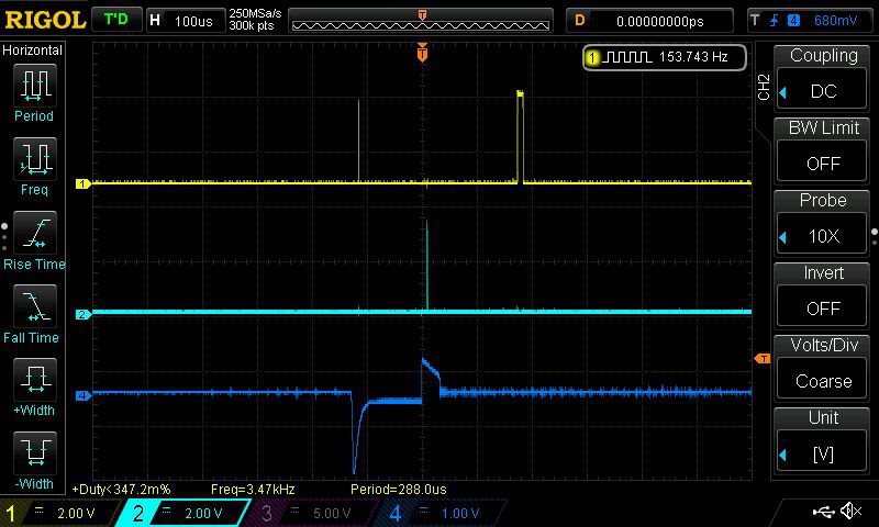
I've figured out the boundary wire and how it works. I finally got the idea to use the USB d+ and d- (p0.29 + p0.30) and output of p0.7 - p0.10 and measure with oscilloscope.. :) (4 wire inputs -> raising and falling each on pos / neg)
The blue is probe directly on the boundary wire.
 |  |
So if negative measurement is before or after the positive, then you know if you are inside or outside wire.
p0.21 select amplification or something, you can detect if you are within 1 meter of the wire or not.
p0.22 probably selects between left and right sensor.
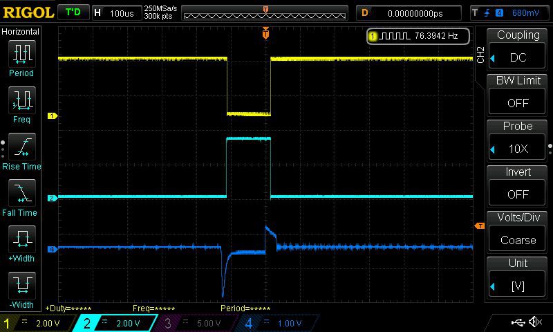
And if you are close to the sensors you get some weird artifacts in the measurement, longer pulse, and even more than one pulse. It seams this is following a pattern and it might be possible to user and detect the distance to the wire at 0cm, 10cm, 20cm and 100cm.
And the last one, wire right on top of the sensor.
Discussions
Become a Hackaday.io Member
Create an account to leave a comment. Already have an account? Log In.
I am sorry about the long text above. I have a WR106SI.1 Landroid S with no bump sensors or otehr.
I had issues with it cutting the wire and wanted to use it in different areas and wanted to be able to manipulate this sensor to be able to add bump or other sensors. Could you elaborate on your findings and any knowledge of how to build more perimeter generators would be appreciated.
Are you sure? yes | no
?I am not great with exploring the posts but access to https://hackaday.io/project/6717-project-landlord/log/37326-guide-wire adds to this post." I found this by change as it was not on the previous/next in case others could not see it. Please see after the line as that is my request for help.
"There are 4 inputs (digital), P0.7, P0.8, 0.9, P0.10) that the original firmware has put on extint3, two trigger on Falling edge, the other two on Raising edge. Probably and each on each sensor.
There are also two control pins (digital).
One is for Range, or Amplification, P0.21.
If I'm close I get triggers regardless of p0.21 state, and then I am far away from guide wire I only get triggers then P0.21 is High.
The other control pin is so far unknown, P0.22. It changes the output on P0.7-0.10. I cannot figure out how this works yet.
The Falling edge's also show if the mower is looking perpendicular to the guide wire; P0.8, P0.10 is high.
If the mower looks 'Downrange', P0.10 is high, P0.8 low.
If the mower looks 'forward', the opposite, P0.8 High, P0.10 Low.
So, any suggestions? My next move is probobly to try to make a logfile of all the triggers, there are around 10-20 per second."
------------------------------------------------------------------------------------------------------------
-------------------------------------------------------------------------------
I think the above is great but do not understand how the robot knows whether it is in or out of the boundary wire especially if not moving.
I would like to make some perimeter wire generators , so I can use my landroid elsewhere.
I have looked at https://www.robotshop.com/community/blog/show/diy-perimeter-wire-generator-and-sensor.
I am going to buy "Xr2206 Signal Generator Diy Parts With Shell Function Sine Wave UK" and hope it may work.
I got the impression it was a 7kHz signal from a web page talking about interference with pet electric fences. I do not understand why this would not be audible though
Any ideas on how to create another landroid perimeter generator?
Are you sure? yes | no