Close
0%
0%

Solar Track Rack

PVC pipe portable sun tracking solar mount

tztz
Similar projects worth following
I saw someone at the recent Ham Field Day that had a solar panel, bu t noticed it wasn't angled perfectly. I also noted the systems to do it were expensive, mainly the mounting, but if you don't face the sun you can lose over 50% of the possible energy (cosine, and is it cloudy in the morning, afternoon, or evening?).. I found some solar cells with a lightweight backing, and\ worked out the geometry.

The subtle thing is the rotational axis has to be parallel to the Earth's axis, but the panels must be angled (0 at the equinoxes, +/-23.4 at the solstices). The sun angle would only need to be adjusted about every week and then only at the equinoxes so could be done manually. But you'd need an axle so it could rotate (more than 180 degrees since the sun goes from northeast to east to south to west and sets in the northwest during the summer).

I'm in an area that is sunny 2/3 of the time, but that isn't the whole story. For an "optimized" fixed mount, the panel would be in shade during the first three hours of the day as the sun would be north and not very high up (my north window bedroom needed blackout drapes since the bright summer sunrise would shine right through).

It is usually sunny through the early afternoon, but it varies. That is why the mount. Many places have different weather including mid-day clouds or rain. A fixed mount will get at best 50%, and only if it is sunny mid-day. With the mount, I'll get almost all the energy when the sun is shining.

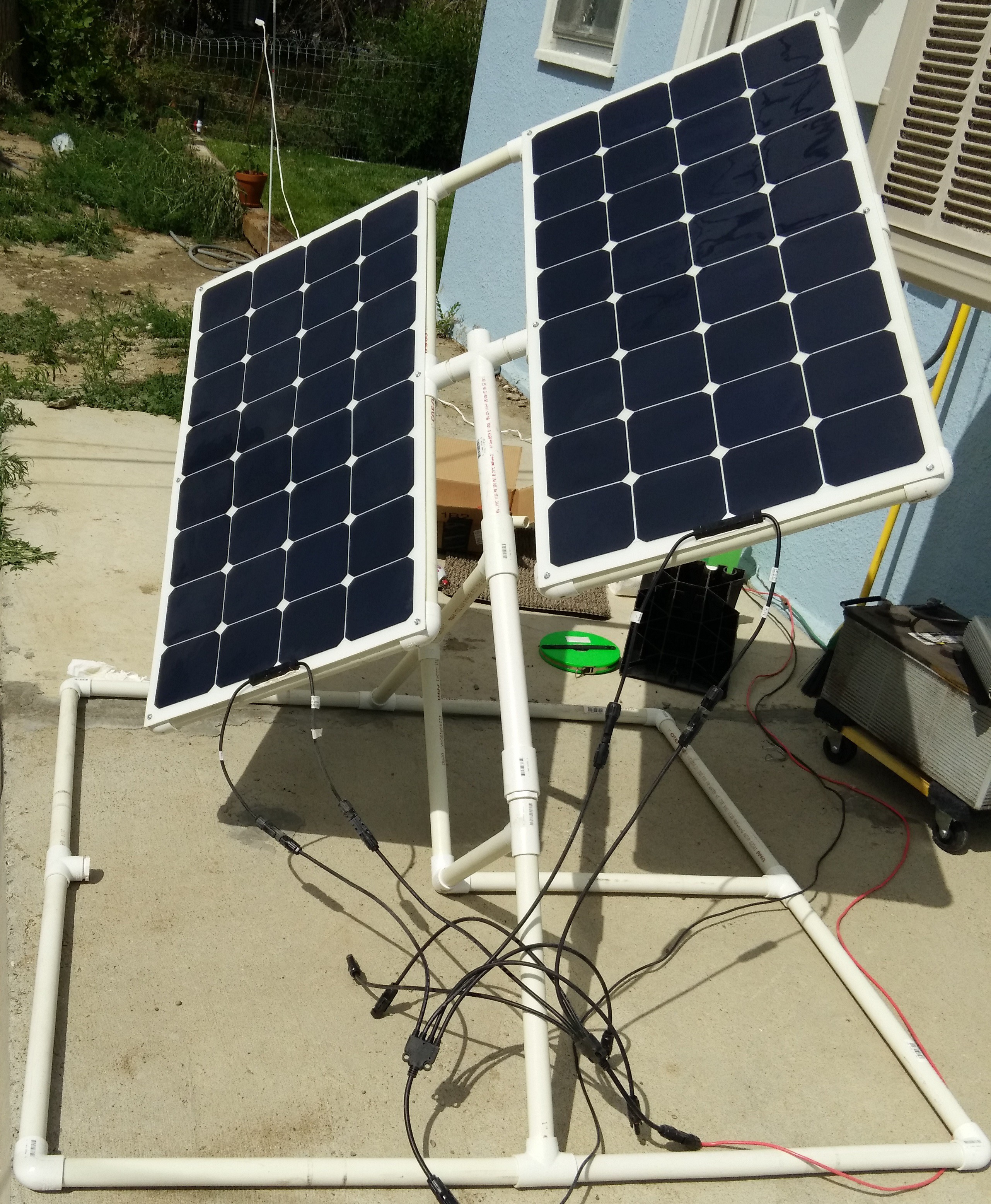
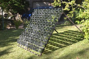
Solar panels are expensive, PVC is cheap. Instead of adding 2x or 3x panels to get more power, I just point the ones I have directly at the sun.


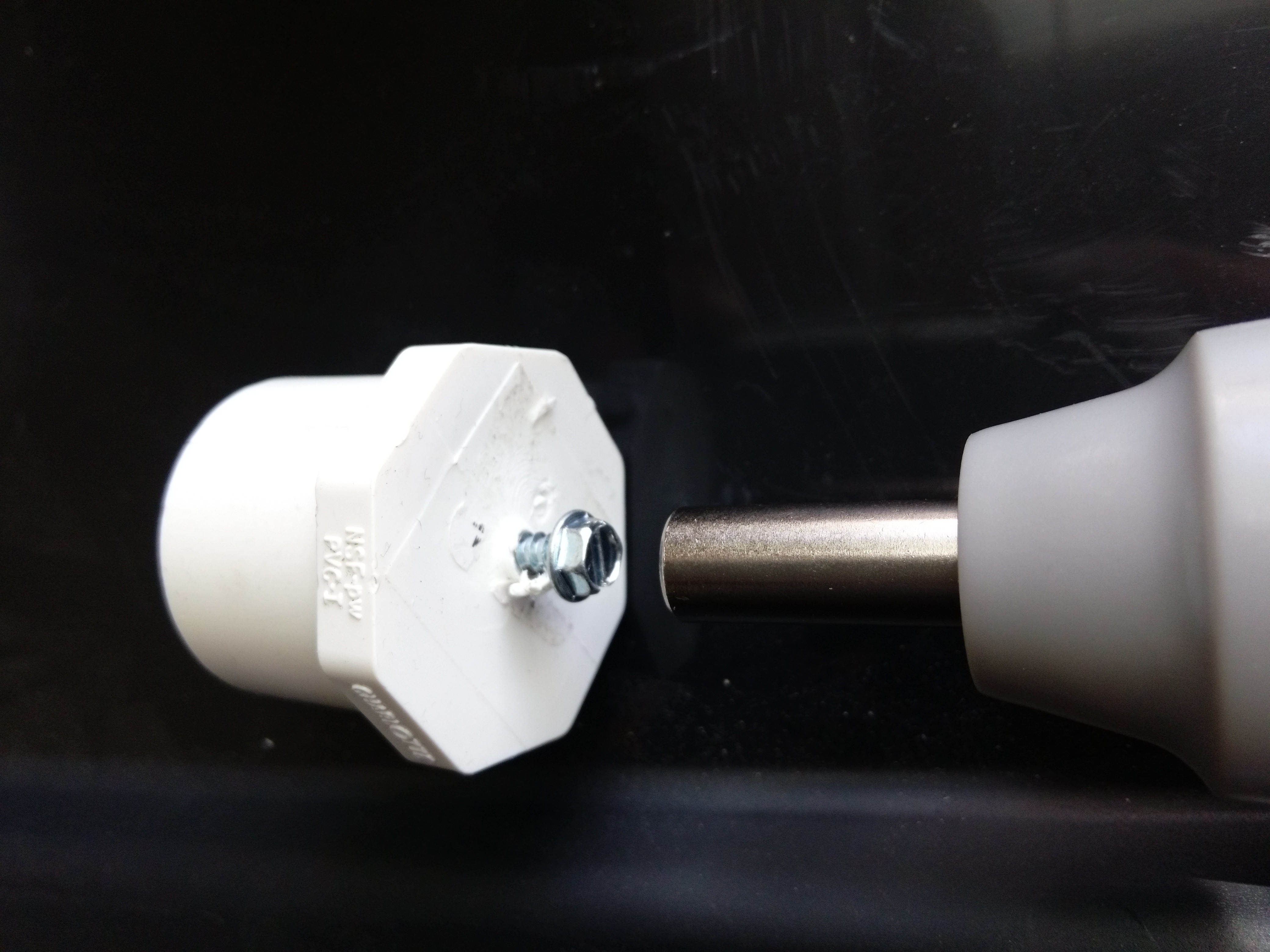
My local ACE Hardware has inexpensive PVC pipe and the 1-1/4 inner diameter will fit a 1" inner diameter pipe inside where it can spin (and they have a second "1 inch" light, thin, but stiff version).

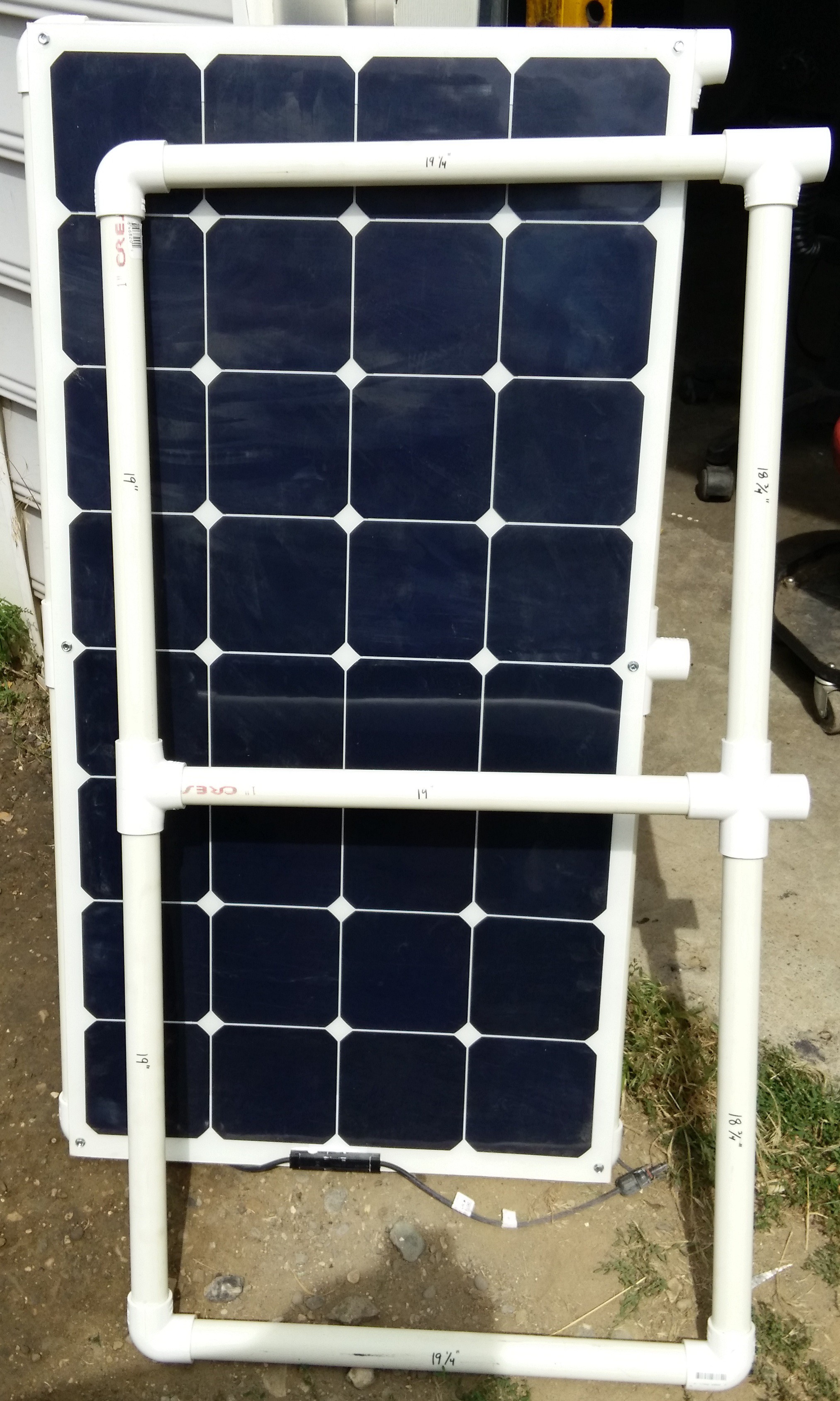
One key is to balance the panels so they won't put much force to turn.

I'm still tweaking the geometry, but have most of it designed and am ready to cut pipe and get the joints. I doubt all the material (except for initial errors) should cost about $50. Lightweight and portable. It would be set up for my Latitude (right near 45 degrees) but if I get too far off, I can place it on an incline to compensate.

For winds and stability, they are pipes which I can fill with water or sand, or put sandbags or weights on them.

There are already commercial "sun tracking" bits of hardware, or I could use GPS or something else to get it to point to the sun - the harder part is the mount and that is what I'm trying to solve.

  • Rotor #3 (pics)

    tz08/01/2015 at 19:17 0 comments

    Here is the latest rotor (I've added another coupler and section of pipe to extend the T on the actual rack, I should have made the top pipe longer, but I can adjust it later)

    The first pic shows most things broken out vertically but where they end up horizontally in the final assembly.

    The motor is inside the thin walled "21 200" piece and is glued inside, and the pipe glued to the gear housing. That piece goes into the coupler on the right. The gear housing fits inside the larger T at the bottom (1-1/4 thru, 1 side) to the middle (bottom pic). The 1-1/4 tube holds the motor in from the left side, and the motor-cork goes inside the smaller and slightly longer pipe (fits into the 1" T or a coupler) which goes all the way to lightly sit on the motor housing.

    I was trying to use a bolt with a hex head and grommet but it wouldn't quite fit right, so I switched to a (real) cork.

    The coupler is held loosely by the T connector, but holds the bottom of the motor.

    The larger pipe supports the smaller. I'm not using lubrication since it seems to work when clean. The T rotates around with the smaller pipe and sits on the housing, I drill a hole in the pipe into the coupler for the wires to come out. The assembled version is pic 3.

    I needed to use a 1-1/8" cork, cut the top off, and drill a hole. And added some glue:

  • Glue

    tz07/27/2015 at 03:51 0 comments

    I should have updates shortly, but the main thing is you need to use PVC cement to prevent bending, sag, etc.

    Although the panels were screwed to the joints, there was enough slop for them to sag bynhaving the pipes rotate.

    Using PVC cement locked thempanels flat and stiff. Also fixed the base.

    Still experimenting with the upright (and the screwdriver body fits loosely into a 1-1/4 coupler).

  • Cosine

    tz07/24/2015 at 17:02 0 comments

    It is why fixed panels work so well, but also an advantage here. 8 degrees off only drops 1%, so for an hour, you still get 99%.

    18 degrees, (about 2 1/2 hours) you are still at 95%. So some slip or error or sag will still give me most of the energy. It doesn't have to be precise.

    But at 60 degrees off - you only get 50%, so if you have clear mornings, but cloudy mid-days you won't get most of the energy.

    Also the tilt is part of the error. If you are pointing at your latitude, or below (you would want more in winter) this adds to the error.

    http://www.grc.nasa.gov/WWW/K-12/airplane/tablcos.html

  • Measure twice, cut once

    tz07/24/2015 at 16:52 0 comments

    Oops. PVC pipe is sold with a little extra. "2 foot" precut is actually 25 1/8 inches. I also had to verify how deep it actually goes into the joints (11/16, elbow and T, 13/16 cube vertex - different brands probably vary more). So I have some recalculation to do for the upright, then some cutting

    To open the MPJA screwdriver, push the two metal posts which are close to where it connects to the battery-motor (dark gray) body.

    I'm also waiting for an H-bridge.

  • Pictures 1

    tz07/20/2015 at 17:40 0 comments

  • Wind

    tz07/20/2015 at 13:21 0 comments

    One expected problem now confirmed (so far not severe) is wind gusts moving the panels - it does. I was hoping for a pull-only design but might need push-pull.

  • First Pass

    tz07/19/2015 at 22:26 0 comments

    Got the solar panels from Amazon, and some thin walled "one inch" PVC pipe, a section of 1-1/4", and various couplers, tees, crosses, elbows, etc.

    The result is in the gallery. Self-tapping screws were used to attach the panels to the pipe (they flex so need support).

    I might need to stiffen it or add some Kevlar thread to avoid the little bit of sag, but it works so far.

    The central cross (could have been a T but I might put the actuator on top) has friction to each side to hold the solar angle (which only needs to be adjusted every few days at most), but going downward is a thick walled 1" PVC pipe that fits loosely inside the 1-1/4 so as to be the axle for the day rotation.

    Next step is the tracker. Dollar Tree has "solar lights" (for $1 each) with a 1"x1" amorphous solar cell that should make a good sensor, and I have a number of AVRs but will probably use a Pololu A-Star and a battery powered (reversible) screwdriver.

View all 7 project logs

Enjoy this project?

Share

Discussions

tz wrote 07/20/2015 at 13:17 point

LEDs or photodiodes are an alternative.  Put a load (small value resistor) on solar cells and voltage depends on current (E=IR).  Current depends on illumination.

  Are you sure? yes | no

sbi.gaijin wrote 07/20/2015 at 07:23 point

I'm looking forward to seeing your progress reports on this one.

I think the solar cells might be too sensitive for this application.  They put out a surprisingly high voltage in what seems (to our eyes) to be low light conditions, so they're going to be difficult to use in the normal two or four cell, differential mode; the shadowed side will still put out a substantial voltage.  I know there's a trend for using LEDs in trackers (www.redrok.com), but you might be able to utilize the solar cells if you buy a couple of pairs of those huge, 1970's sunglasses that Dollar Tree has had in stock for the last  40 years and use the lenses to cut down the light reaching your cells.  :^)

Despite the slightly tongue-in-cheek suggestion, I -am- looking forward to your updates (I'm  crap at mechanical design myself).

  Are you sure? yes | no

Similar Projects

Does this project spark your interest?

Become a member to follow this project and never miss any updates