 Johnny
I've now reverse engineered the JP-1482 board and drawn a schematic of everything.
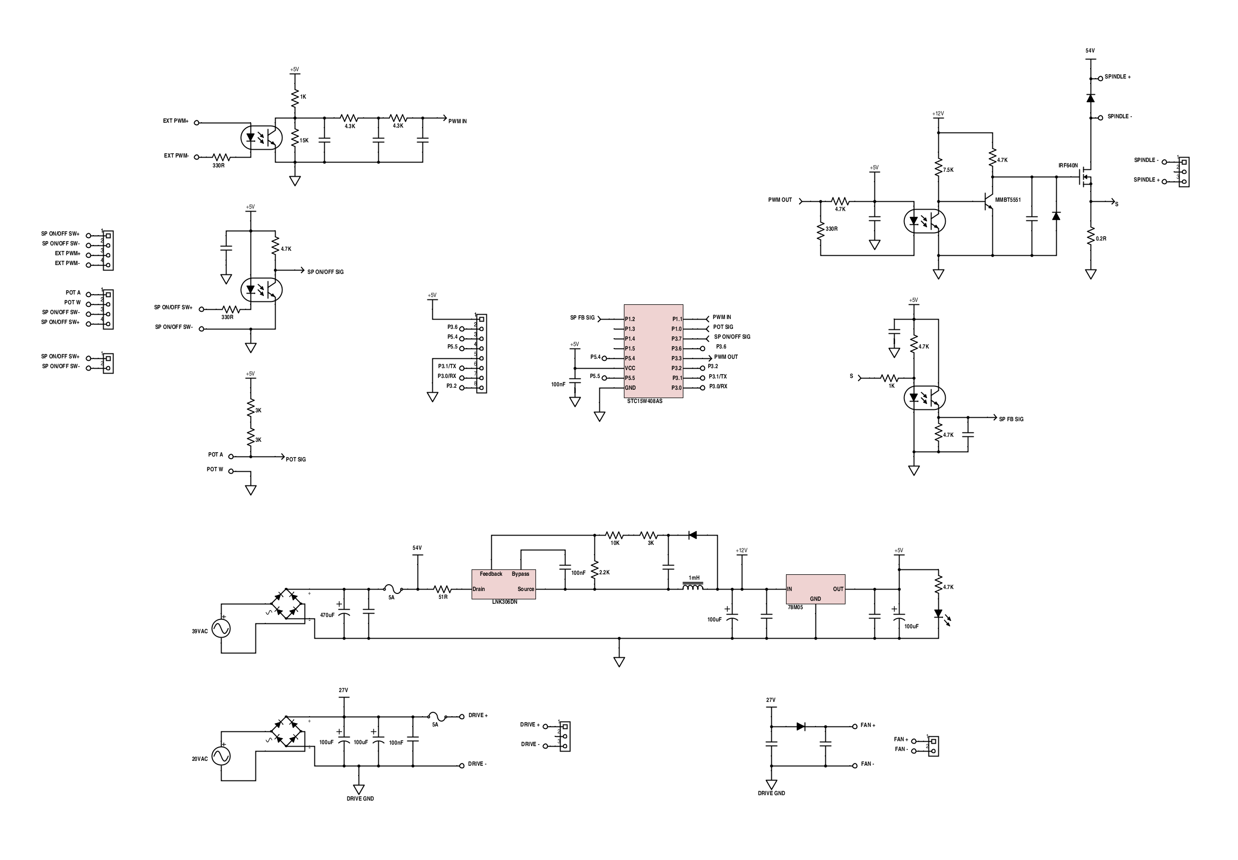
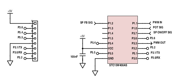
The micro's connections:
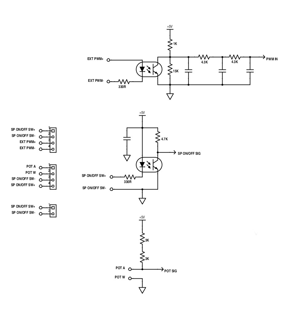
Control signals:
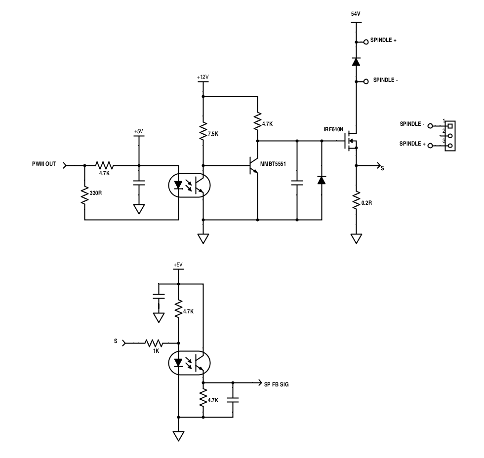
Output to spindle and overcurrent detection:
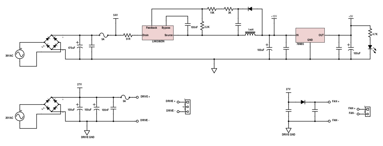
Power supplies and fan output:
A project log for 3040 CNC Milling Machine Mods
Upgrades to 3040Z-DQ
I've now reverse engineered the JP-1482 board and drawn a schematic of everything.
The micro's connections:
Control signals:
Output to spindle and overcurrent detection:
Power supplies and fan output:
Discussions
Become a Hackaday.io Member
Create an account to leave a comment. Already have an account? Log In.
Hi all, Thanks for posting the reverse engineered schematic, it came in handy. In the process of tearing down this badly engineered product, I've discovered a few things that may be useful to anyone owning this T-D Controller. First of all, the 24 VDC wiring for the stepper board has red for ground, and black for 24V. Easy to blow a 5A fuse if you are not aware of this. My 3040T is made by Vevor, and the quality is generally good, but the spindle controller is limiting the power that should be around 400W to somewhere less than 240 Watts (P=V*I). Notice the 5A fuse in the 54VDC circuit will blow somewhere near 250W and the spindle will never reach it's potential. This controller is so badly engineering, so I'm replacing the whole thing with some Digital Drivers, a couple of 48vdc DIn supplies, a bog standard BoB and a Real spindle controller. Just thought that cnc folks should know what they are getting into...
Are you sure? yes | no
I'm not sure but assume I received ( as a port of the MINI-CNC ENGRAVING MACHINES T-D ) a clone of the spindle circuit above based on a 8051 microprocessor. Unfortunately there are NO names added to the two connectors. I have a picture of the circuit available. Anybody came across this spindle controller?
Are you sure? yes | no
Does the PCB look the same? If so I can let you know what pins are what.
Are you sure? yes | no