 Charles Ahrens
I wanted to create a circuit diagram in order to figure out how I was going to fit all the components on the circuit board and how they were all going to connect together. I don't want to spend the money to get a custom printed PCB, and I don't have the components to do my own toner transfer and etching method, so I will use a solderable perfboard to wire everything up.
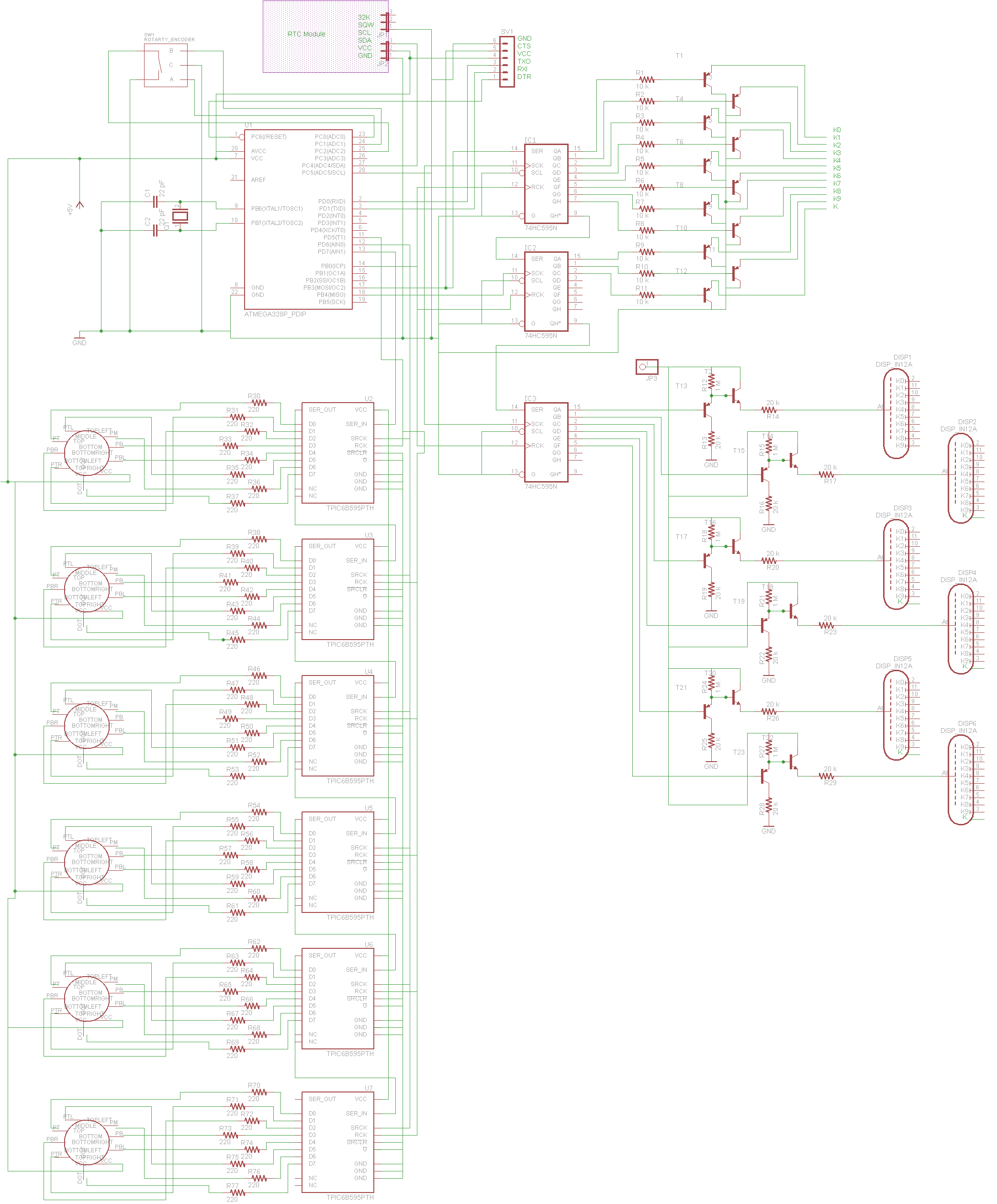
As shown in the circuit diagram, the cathodes of the Nixie tubes will be run through shift registers connected to high voltage transistors that will dump the current to ground, while the anodes for the Nixie tubes are connected through another shift register and high voltage transistors in order to supply the 180V supply and multiplex the tubes.
The Numitron tubes, however, will all have their common connection to 5V, then the cathodes will be dumped through the high current shift registers. I have it designed to have 6 of these shift registers, but I might change that to have the Numitron tubes multiplexed as well. I'm not sure yet, I will have to do some tests to determine which method is better.
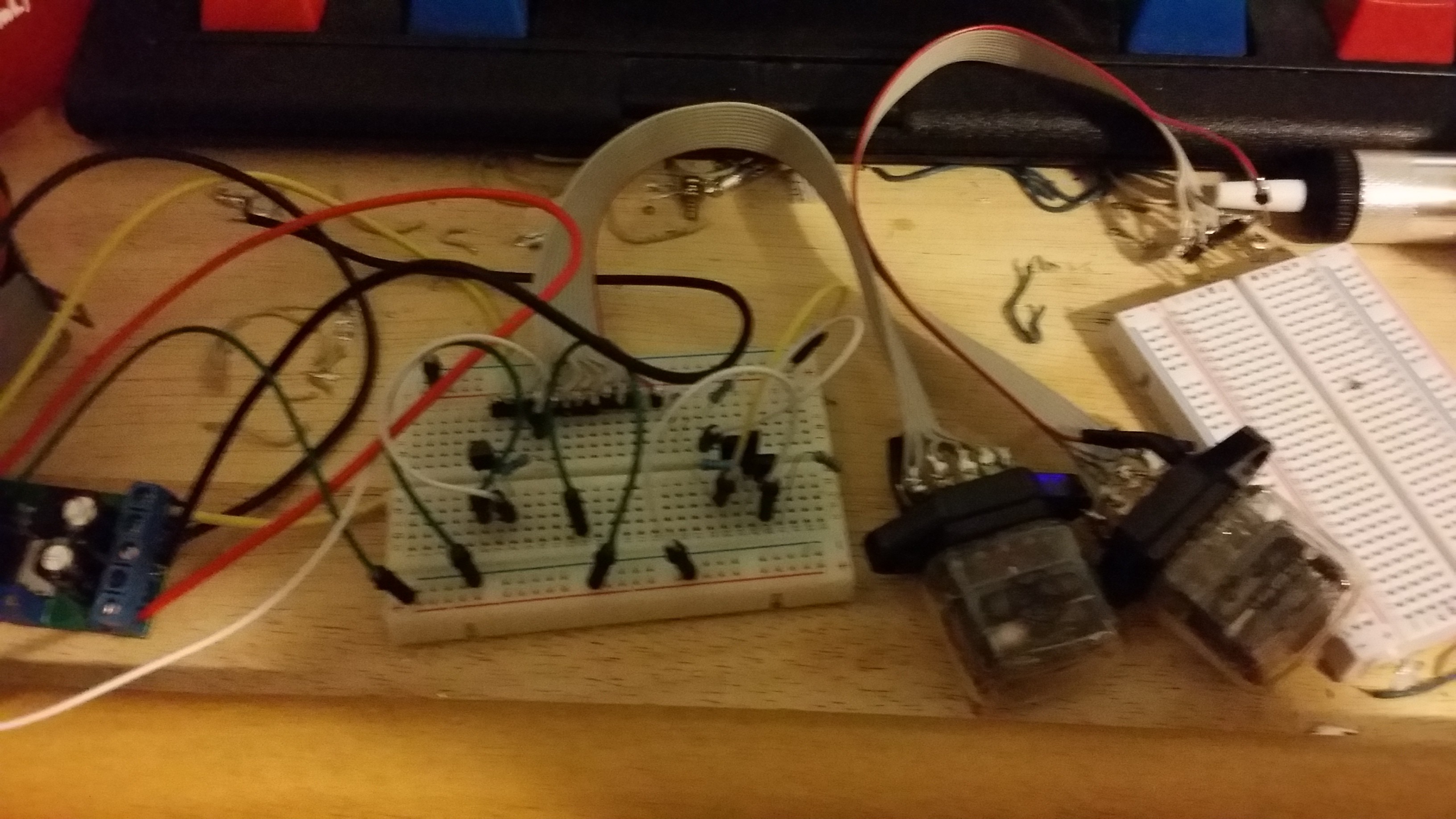
The test of the high voltage transistors is shown below. I wired these up with a 5V and a 180V power supply to check that the tubes would light with the correct anode resistor value, as well as not burn out either the transistors or any of the circuit. Luckily I ordered 25 of each MPSA42 and MPSA92 (NPN and PNP) so that I can have a few extra when I inevitably burn one out from faulty wiring.
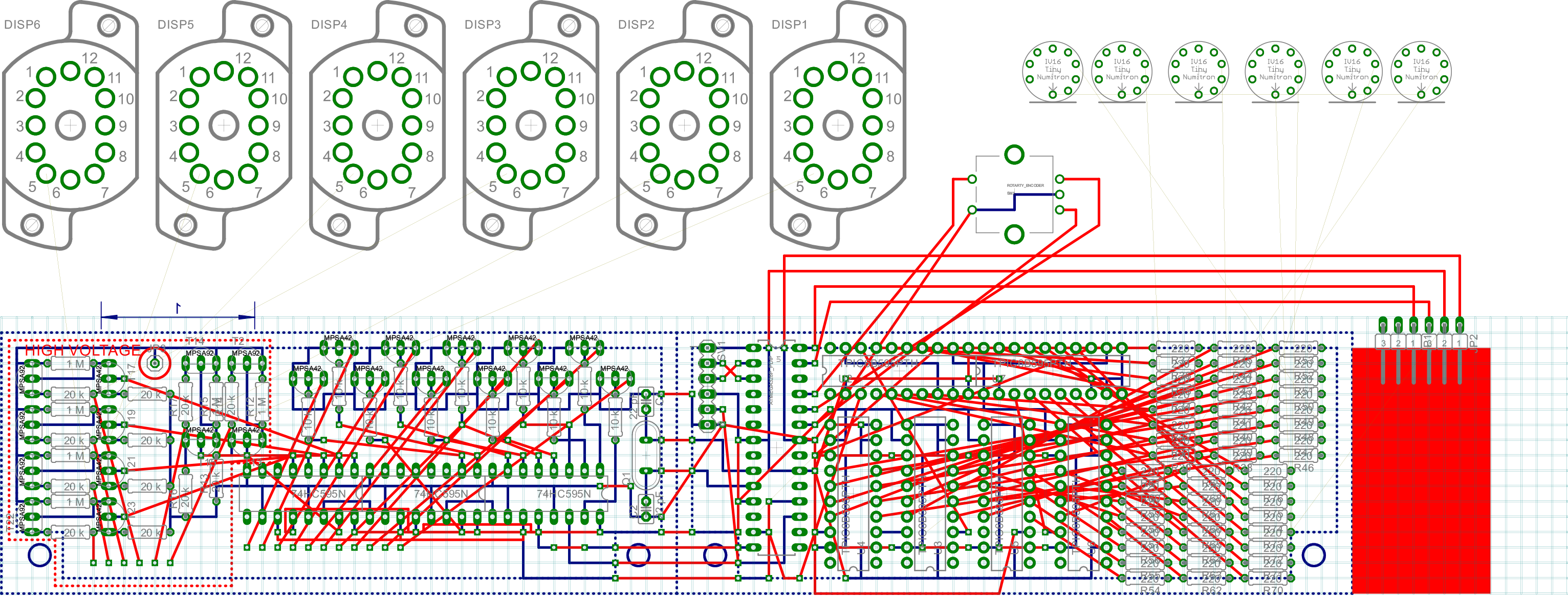
Once I ensured that the circuit would work, I designed a PCB in EAGLE, with the intention of copying it to solderable protoboard with a sharpie and then soldering over it. I bought single sided protoboard, so the soldering will be on the bottom, and the top layer will have loose wires connecting the different chips and bridging gaps. As shown in the PCB, there will be only a single rotary encoder (with a built in button) to navigate the setting of the time, as well as enable me to switch between temperature display, day of the week, and date.
Discussions
Become a Hackaday.io Member
Create an account to leave a comment. Already have an account? Log In.