 John
JohnHow it Works:
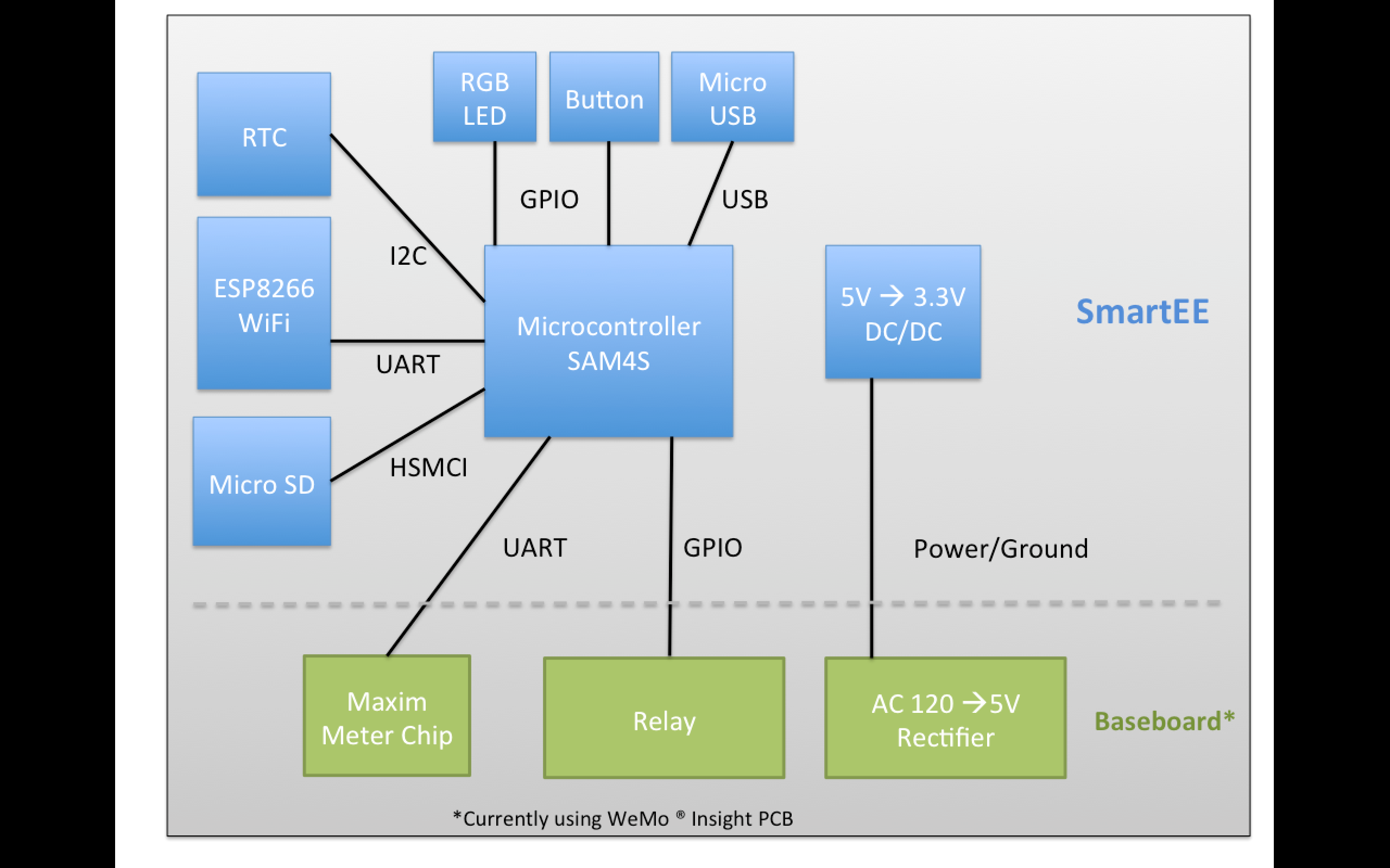
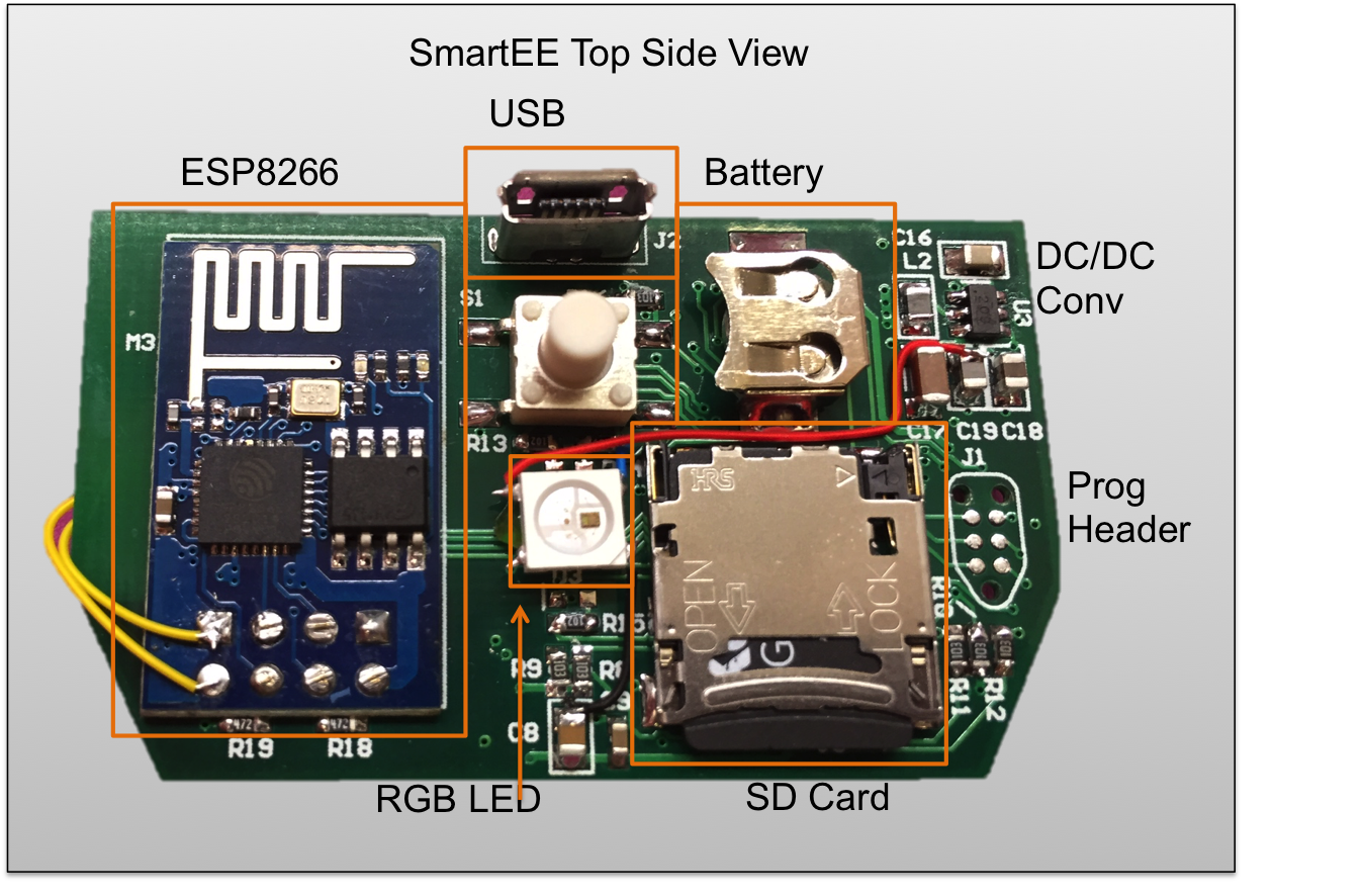
SmartEE is an opensource hackable smart plug. You can turn on and off loads and monitor power consumption all over your home or lab's WiFi network. Its easy to customize - just import the plug.py python module into your code to add SmartEE's to your own project.
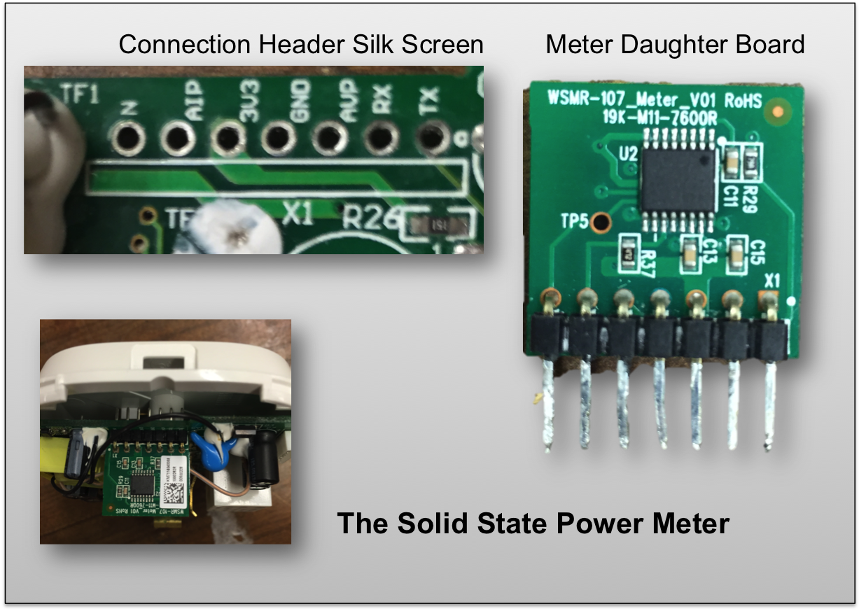
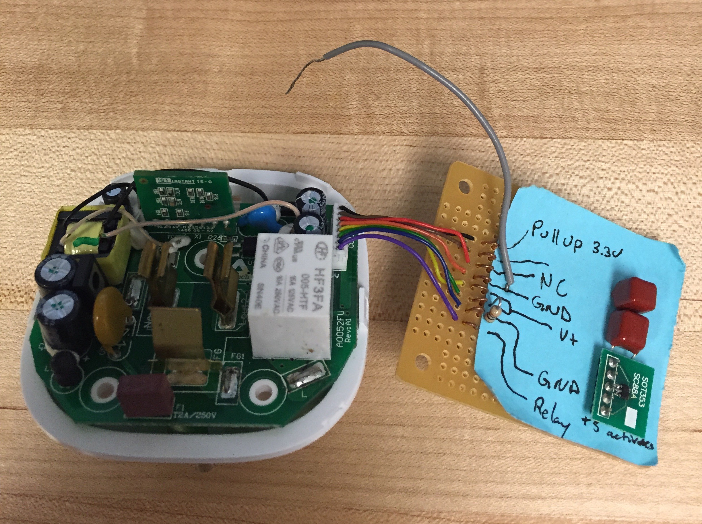
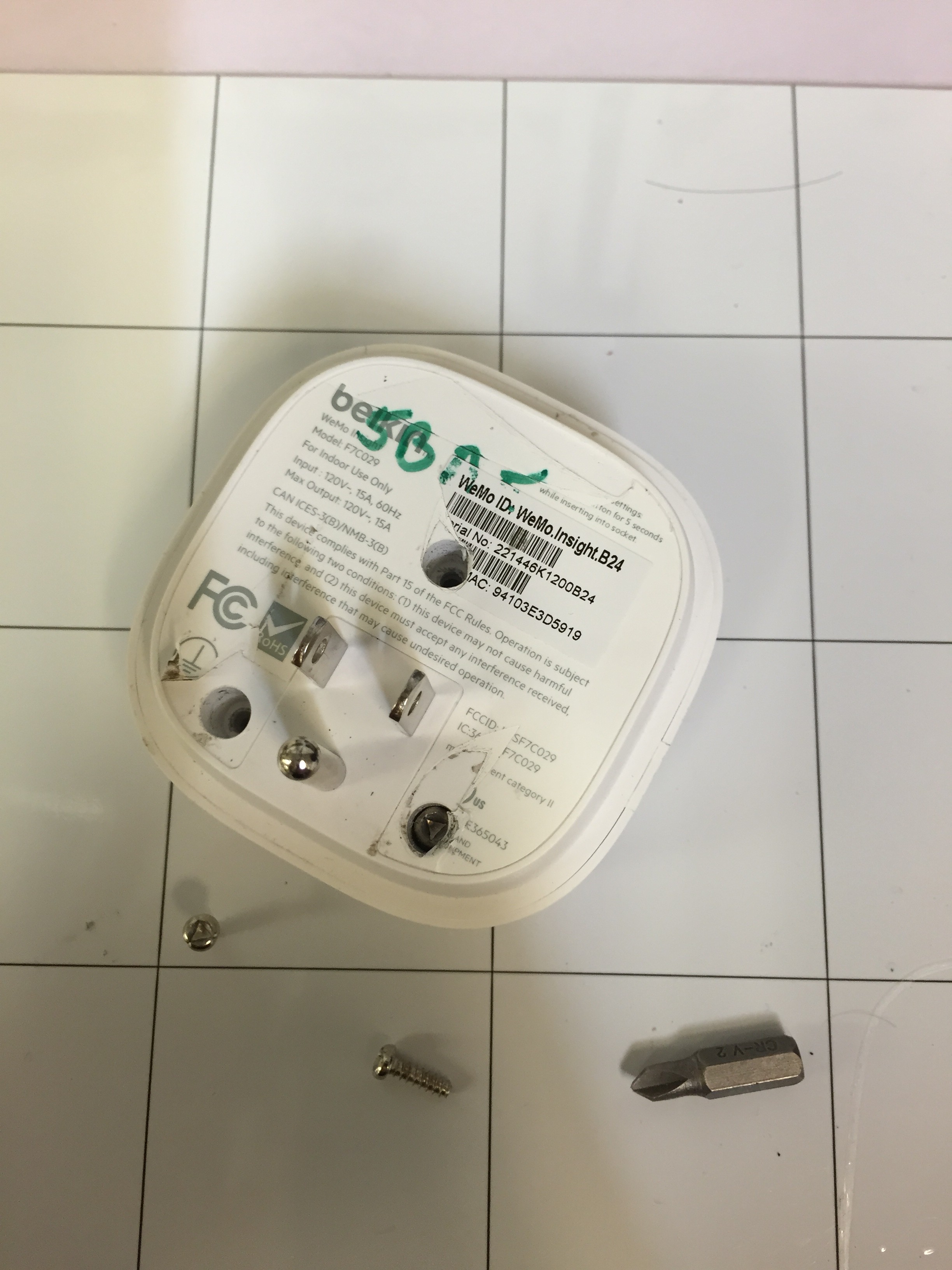
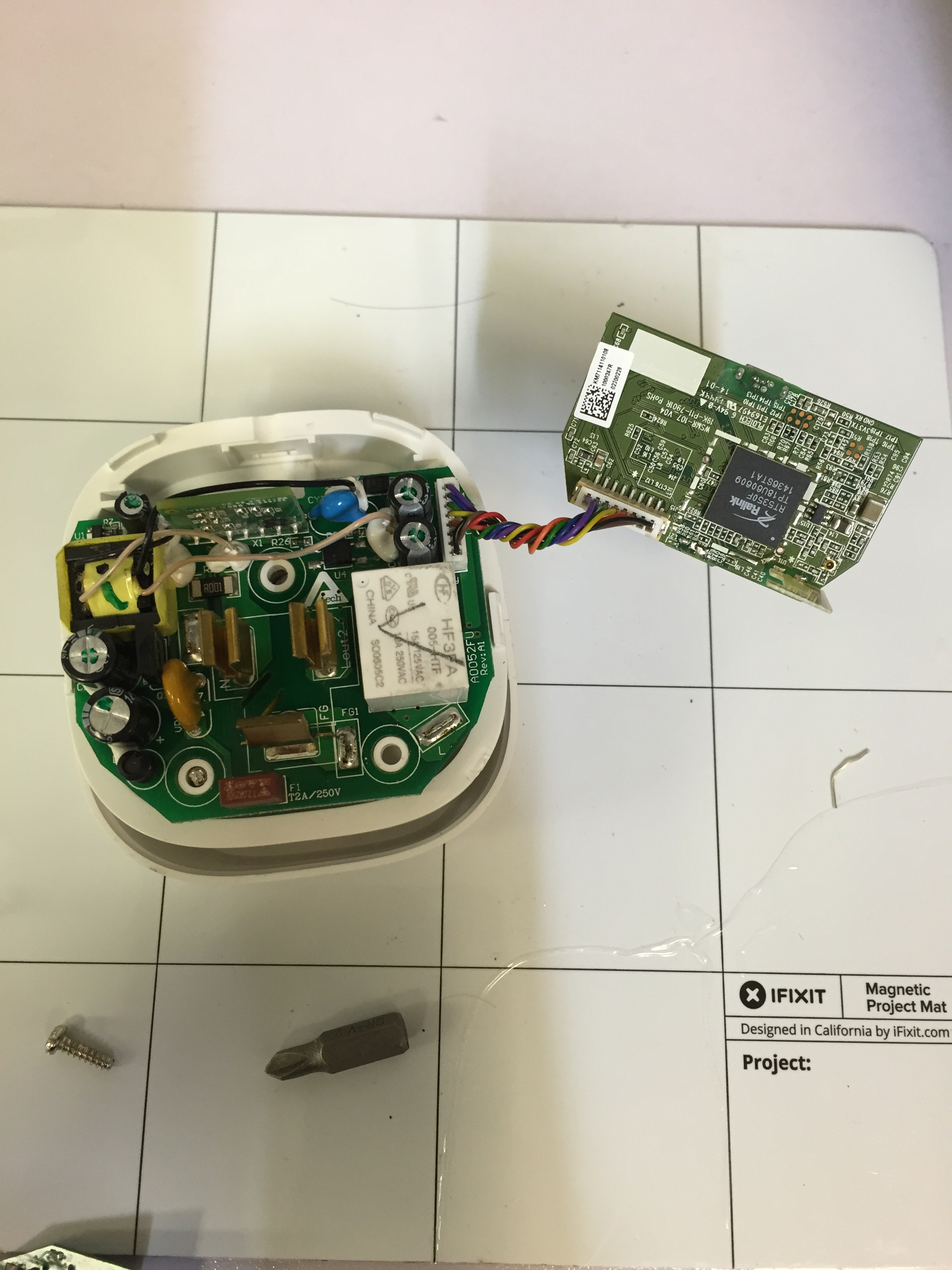
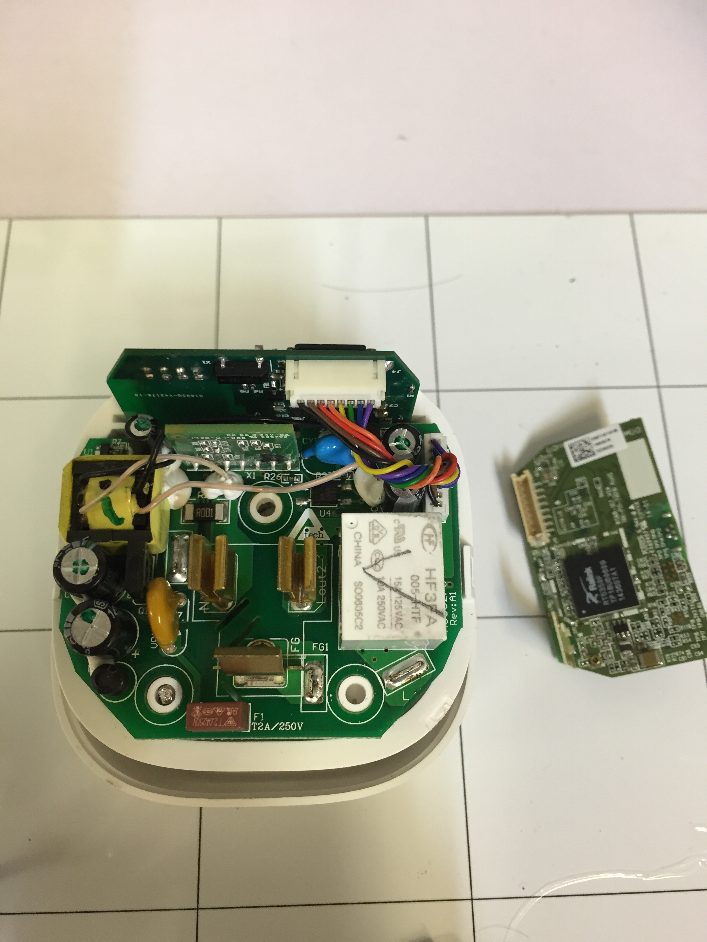
Right now the project uses the WeMo Insight's enclosure and base board. Designing UL certified enclosures is straight forward but expensive. If I get some money ( !! ), I'll invest in the injection molding dies to make the SmartEE a standalone device.
Why would I want this?
The stock WeMo (R) is a pretty cool device but you can only use it through the app they provide or with a few third party services (eg IFTT). These tools only expose a fraction of the plug's monitoring power and do so with limited API's. By switching to the SmartEE you get all of the stock functionality plus:
- High bandwidth data logging (0.5 Hz sample rate)
- On board storage with up to 4 years of capacity (uSD card)
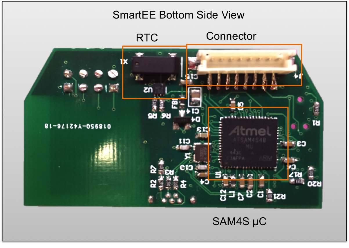
- Real time clock (RTC) for precise time stamps
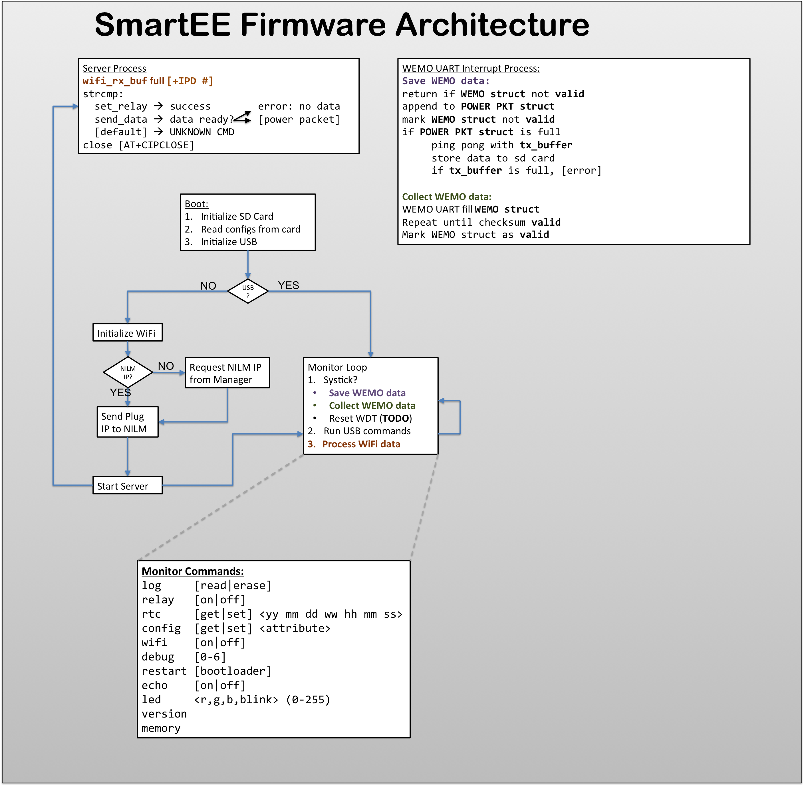
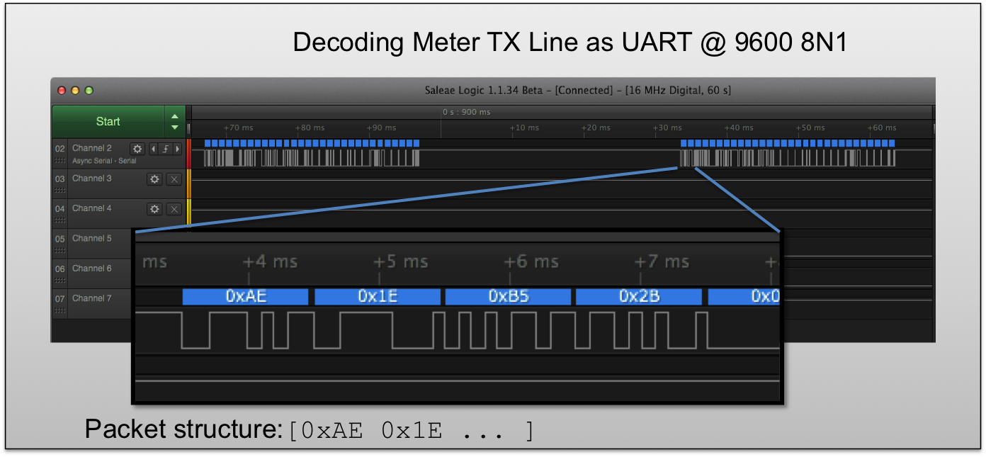
- Advanced power metrics in addition to just power usage including:
- RMS current
- RMS voltage
- Average power
- Watts
- Power Factor
- Line Frequency
- Total energy
And of course its all open source so you don't have to worry about changing API's or third party cloud services peering at your data.
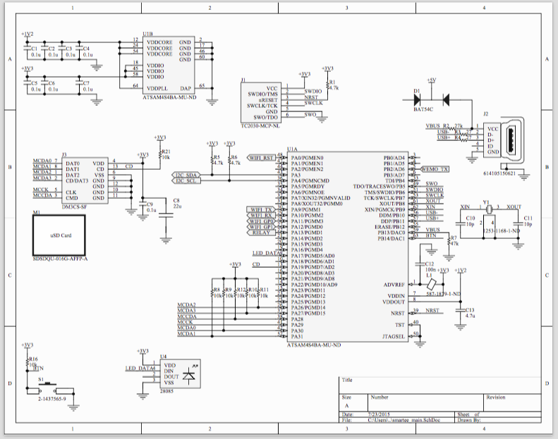
All of the source is available on github including hardware schematics, gerbers, firmware, and software examples. Check out the drop box for pdf versions of the hardware docs.
Check out the project logs for more details.


 jlbrian7
 David
David
 Ashwin K Whitchurch
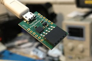
 Luke Valenty
Hi John, is there a way I can plug and play this for power monitoring ?