 Montassar
The Code:
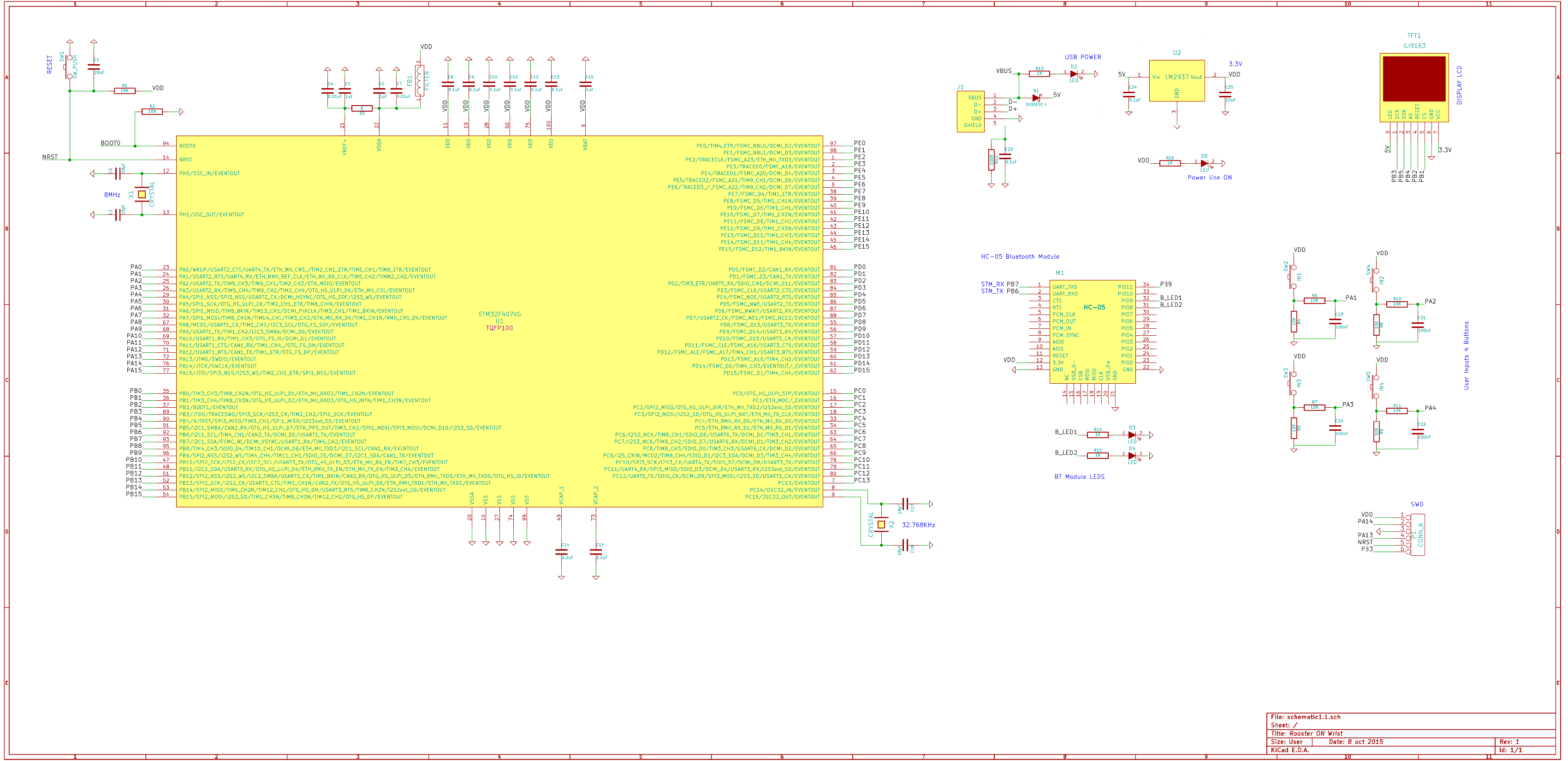
Just like many of hobbyists out there I use CooCox with GCC for my projects and that's a major key factor why I chose ARM over PIC32 MIPS , the free IDE and C compiler.
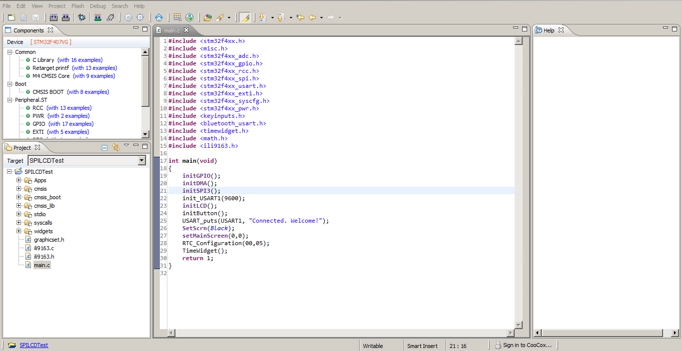
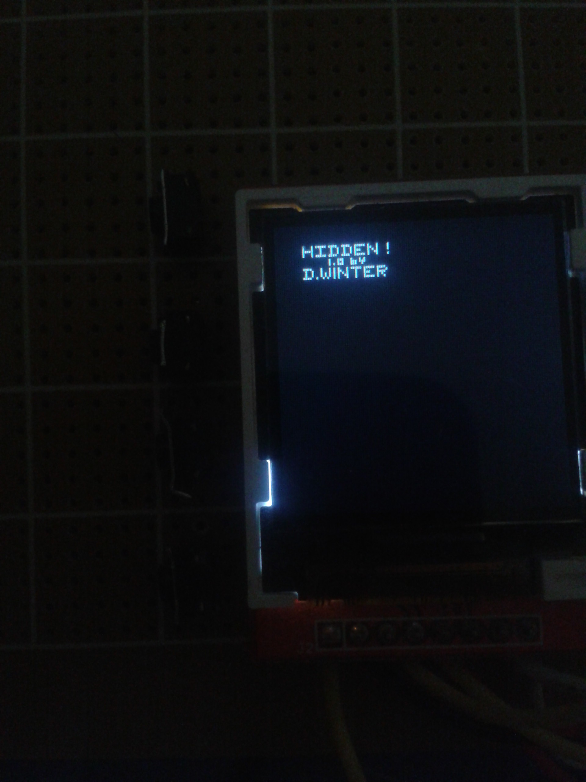
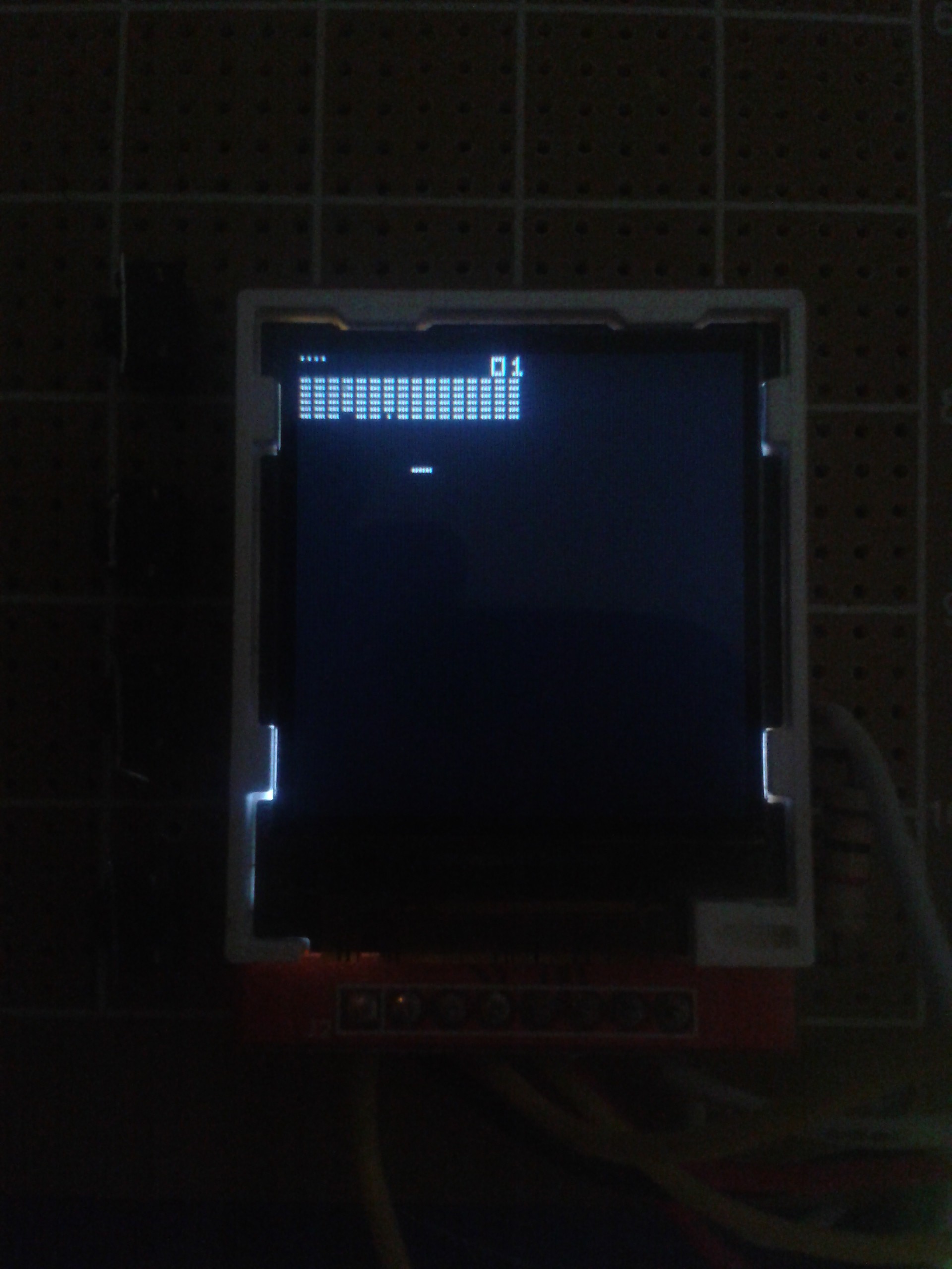
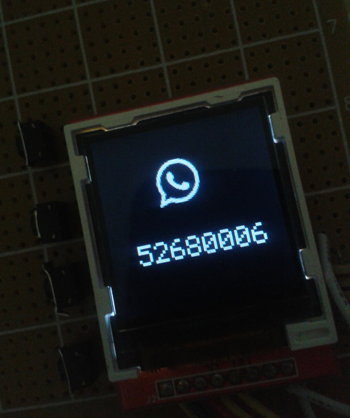
The first step was to interface the tft lcd , I looked up online and luckily I found many useful blog posts about using the ili9163 tft lcd. Obviously I could have checked the datasheet and write my own library which I eventually did and managed to get something on the screen (a bitmap of what I imagined)
This TFT LCD uses SPI and is interface to SPI3 on the discovery board. I use DMA to make it even faster to loads frames ( thought I did not see much a difference )
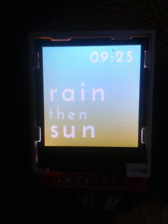
I kept working on the display library because it was a key factor in handling most of the work here.
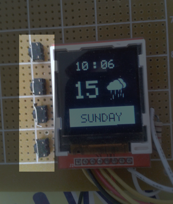
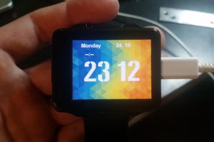
Next I wrote the code for the RTC unit, which has two main functions RTC_Configuration() which sets the RTC configurationa and TimeWidget() which constantly keeps track of the time and updates it on the screen.
The bluetooth module:
The hc-05 is connected to the USART1 unit pins and triggers an interrupt which stores the data received from the phone and calls RTC_Configuration() to sync the Time/Date from the phone.
The Mobile App:
When I first started I had to use an app called BlueTerm on Android, it's an extremely useful Bluetooth terminal app that allowed me to communicate with the HC-05 module and send data manually to test my code.
Later on I learned about App inventor by MIT and it was like few minutes untill I got my first companion app done. It reads automatically the time on the smartphone and syncs it to the device.
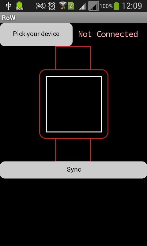
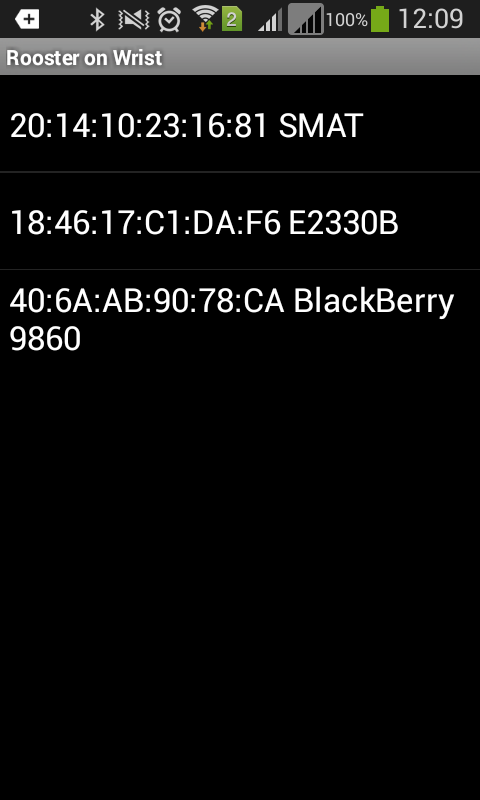
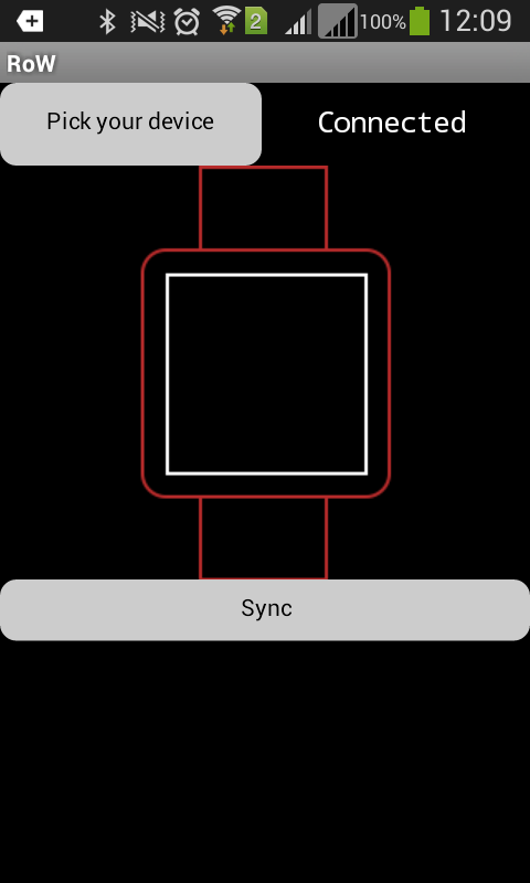
android sync app screenshots
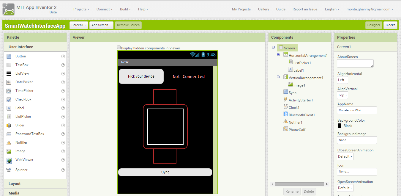
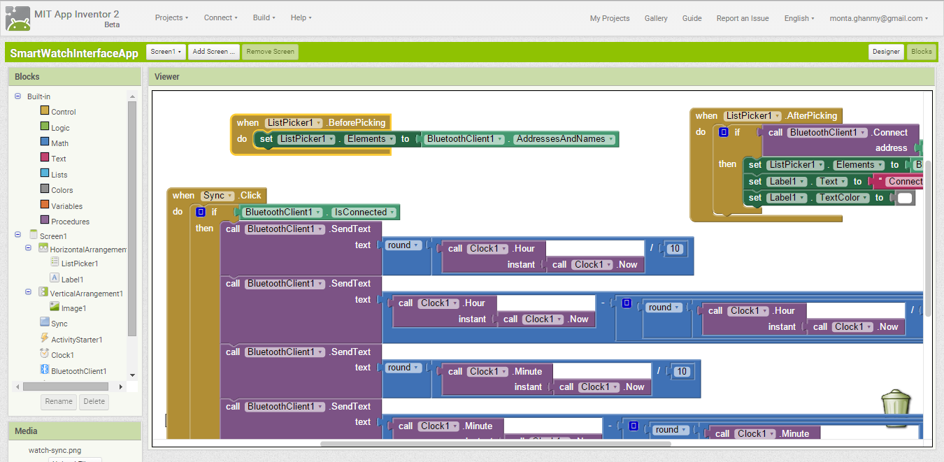
appinventor2 screenshots
What's Next ?
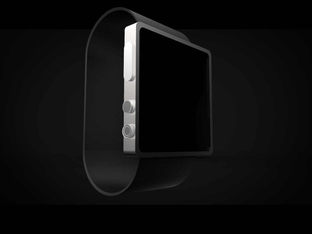
From the begging the goal was to create a complete smartwatch with complete functionality.
What's left to go:
- Improving the software, adding more watch faces, adding apps and notification sync.
- Improving the android app and sync incoming calls and weather.
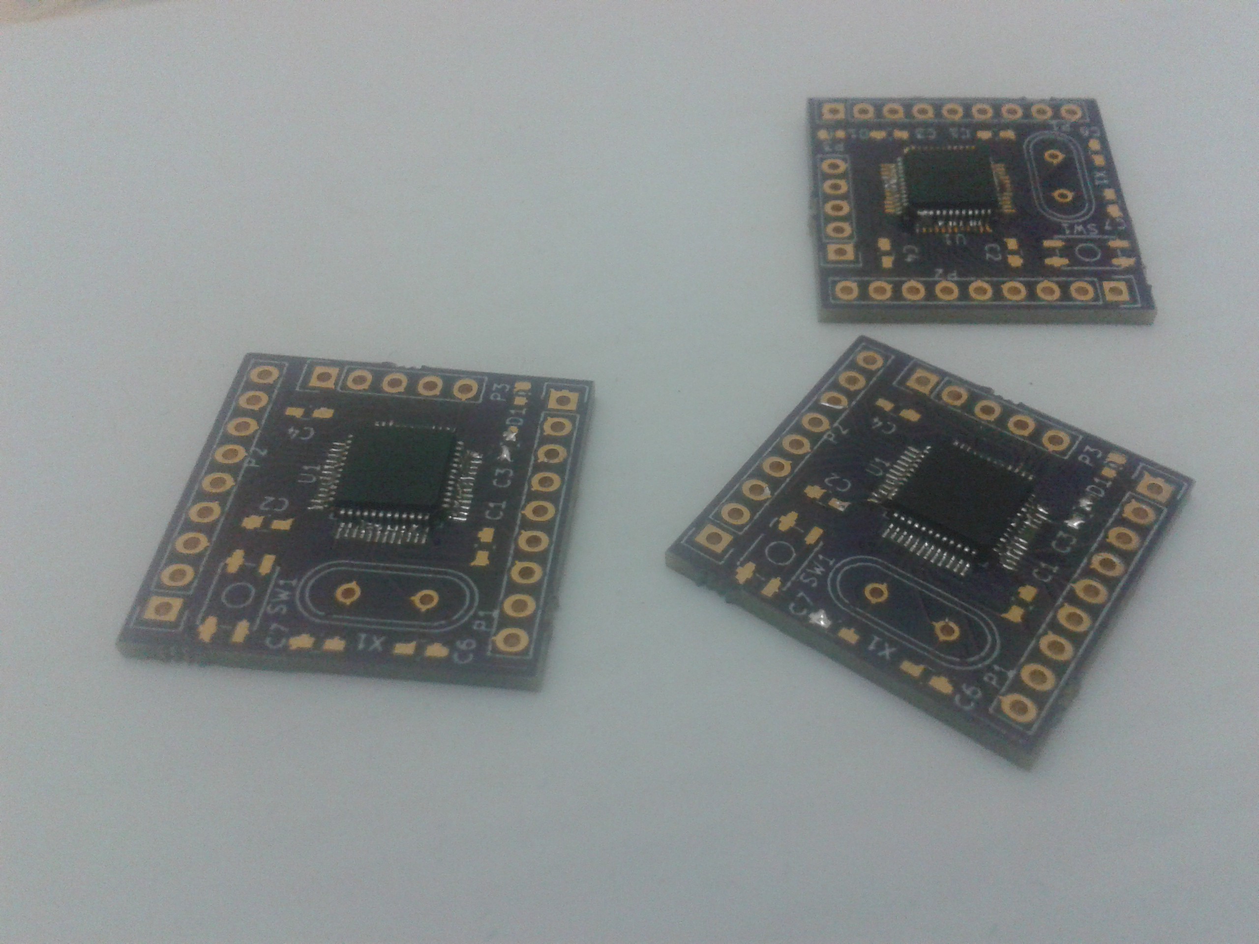
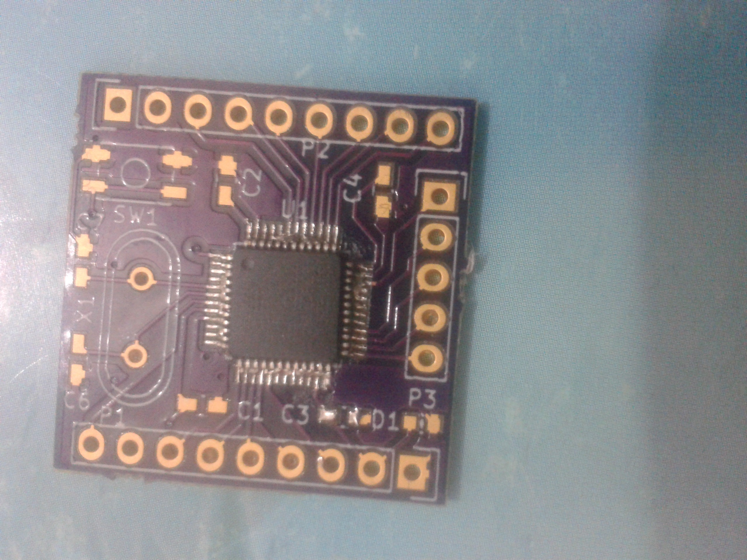
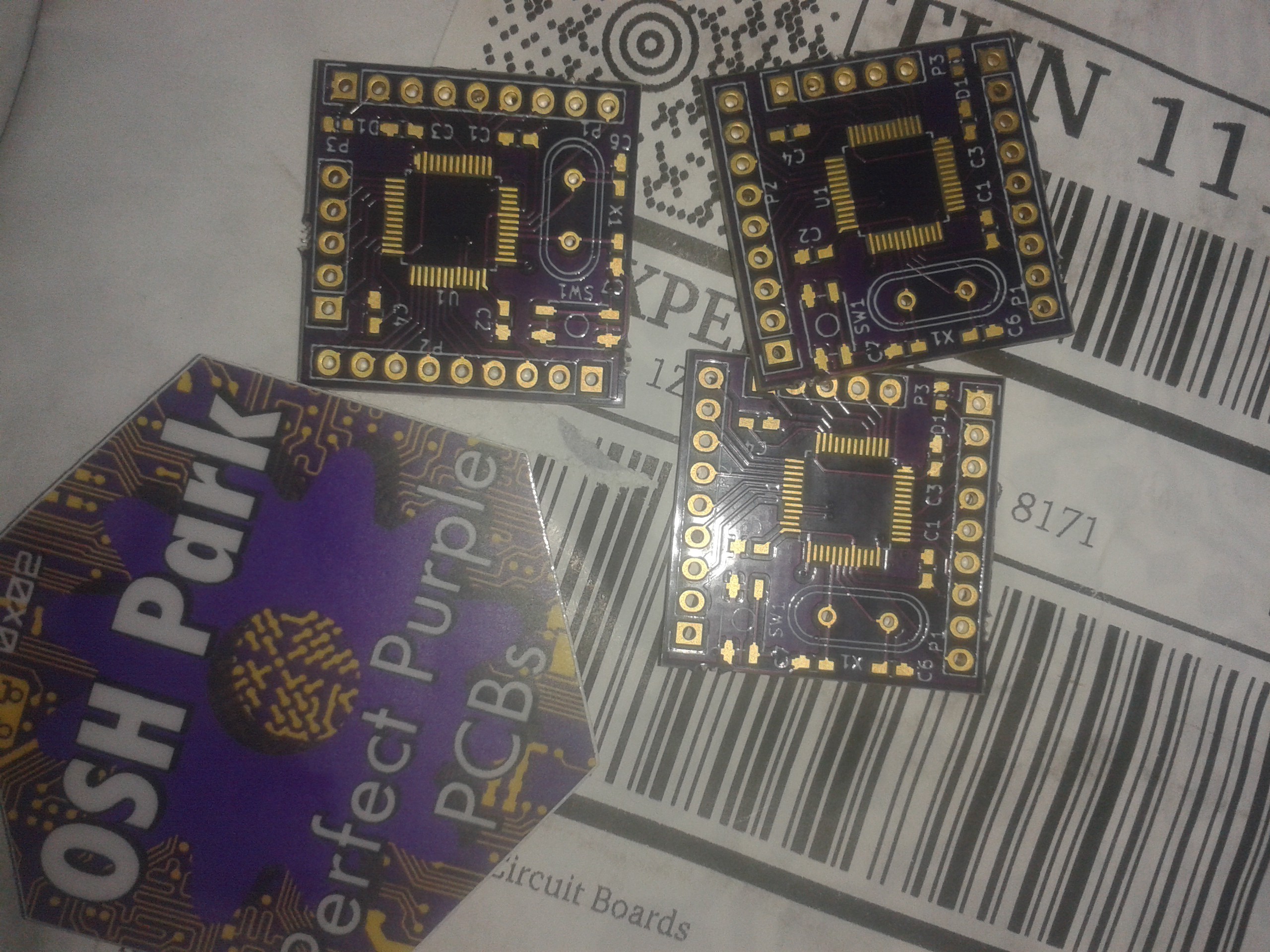
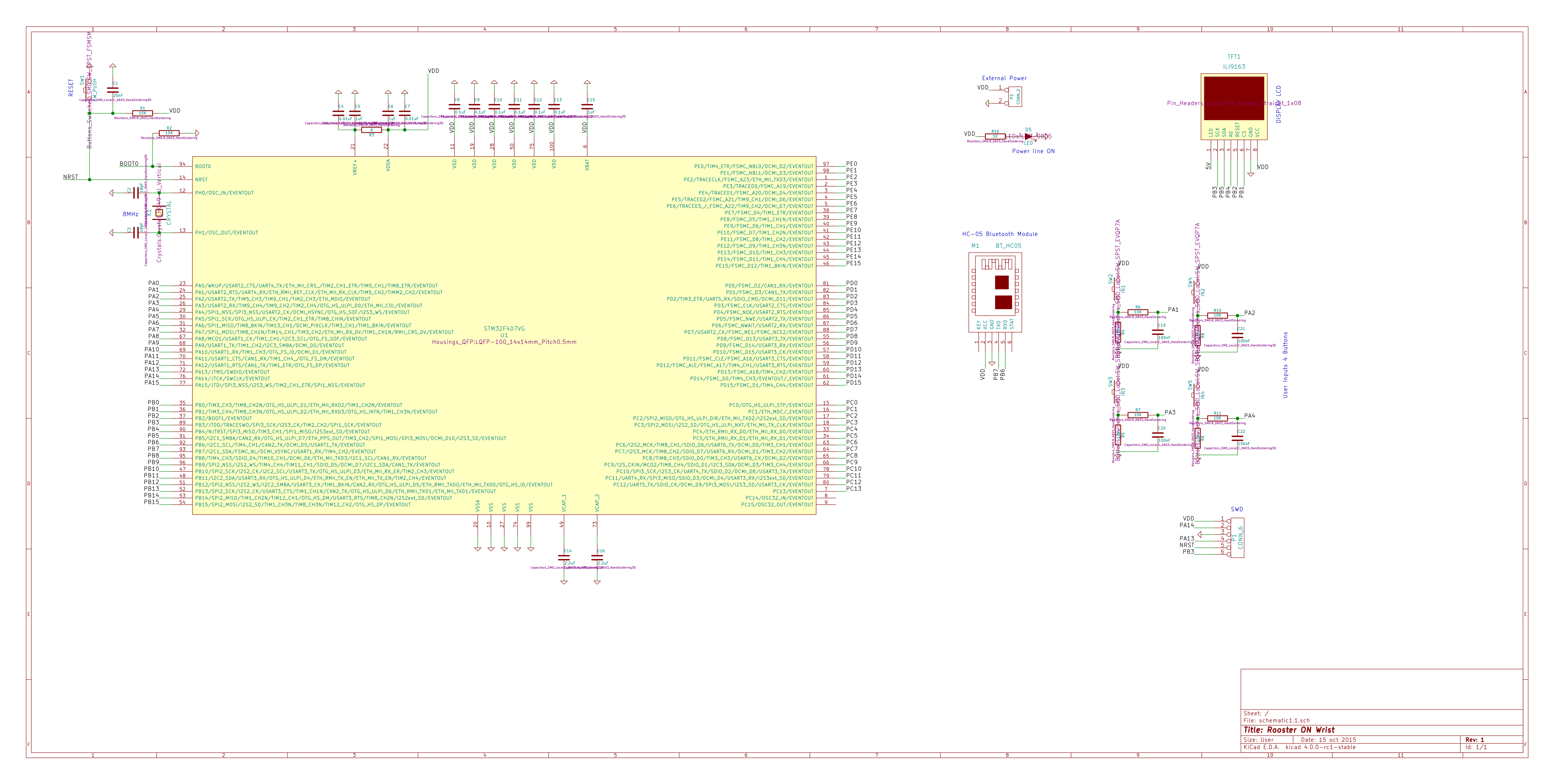
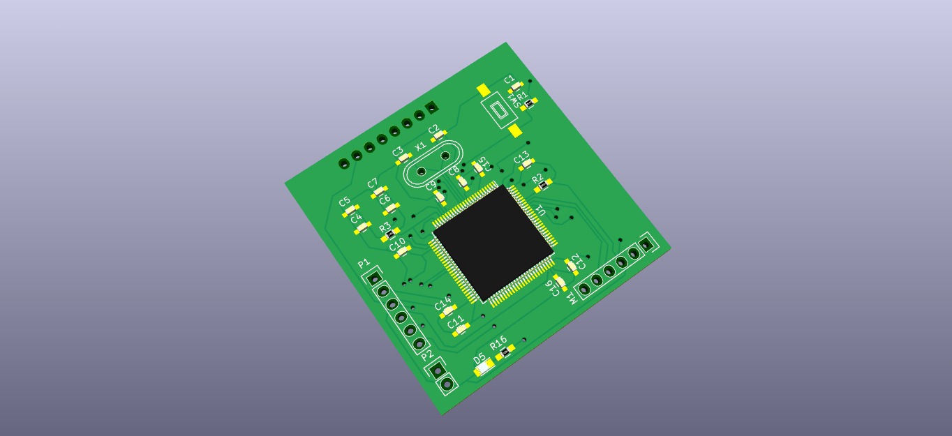
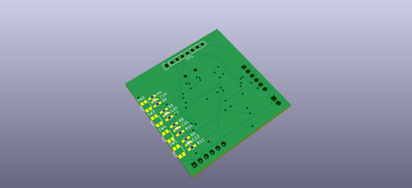
- Build a small PCB for with the STM32F407 or STM32F051, add battery (with voltage regulator and controller ic) , add a SPI 16MB flash memory to store all bitmaps.
- Use a BLE module instead of the HC-05
- 3D Modeling a case and manufacturing it.


 Next step ?


 Peter Wasilewski
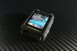
 WΛLLTΞCH
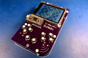
 Piotr Esden-Tempski
Hey there— I can't seem to find your design files. Could you post a link?