 Chris Hamilton
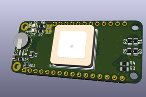
This Flex Module uses the new MAX30100 module. Requires a 3v3 VDD input for the LEDs. Also requires a 1v8 power source, so we added a tiny SMPS onboard powered from the VDD. 1v8 SMPS is around 500mA, so the board provides it to auxiliary boards through a pin out. We need to make the driver once we have a board ready.
Any software related will be released under BSD or MIT license. SAAS or cloud based software will be AGPL.


 Alistair Jordan
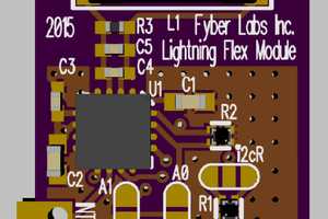
 sirmylesavery
Hi, in case someone needs it, I made a code to read the Infrared data and plot it in the pc via serial port with the software SerialPlot. I'll leave it here. https://mega.nz/#!lxNUGabb!kZQF51G4X880iESr4EPBIMfcDMrOi1_C-XqQXmHDWXo