Close
0%
0%

LowFER Transmitter for your Arduino

Transmit on the license free Longwave band using your Arduino!

Similar projects worth following
Build an Arduino powered transmitter for the little known "free band" at 160KHz-190KHz. If conditions are right, you could potentially transmit for hundreds or thousands of miles. This project makes use of the Arduino's PWM circuit to directly synthesize CW or FSK transmissions.

The LowFER bands consist of several frequency ranges, but I will be focusing primarily on the United States 1750 meter "free band" between the frequencies of 160KHz and 190KHz. This band is covered by Part 15 and no license is required.

This band has some specific requirements, but they are easy to meet:

  • Maximum input power into feedline and antenna system is 1 watt
  • Maximum antenna length is 15 meters (approximately 50 feet)
  • Upper harmonics must be 20dB down from fundamental carrier
  • CW, AM, and SSB modes are specifically permitted

The reality of the situation is that antennas are extremely inefficient that such lengths, and only a small fraction of the power will be emitted out of the antenna. Under the right atmospheric conditions, CW beacons have been received thousands of miles away.

You can read more about the LowFER, MidFER, and HiFER bands here: http://www.lwca.org/

With some minor tweaks, this code and circuit can be tweaked for other LowFER and MidFER bands.


  • 1 × Arduino Most any type, but mainly Uno and Mega
  • 1 × 50 feet of wire Wire can be of any type. I use simple isolated hookup wire
  • 1 × Various inductors, capacitors, and resistors you can find

  • Holy Broadband Noise, Batman!

    Casey Halverson07/27/2015 at 07:18 0 comments

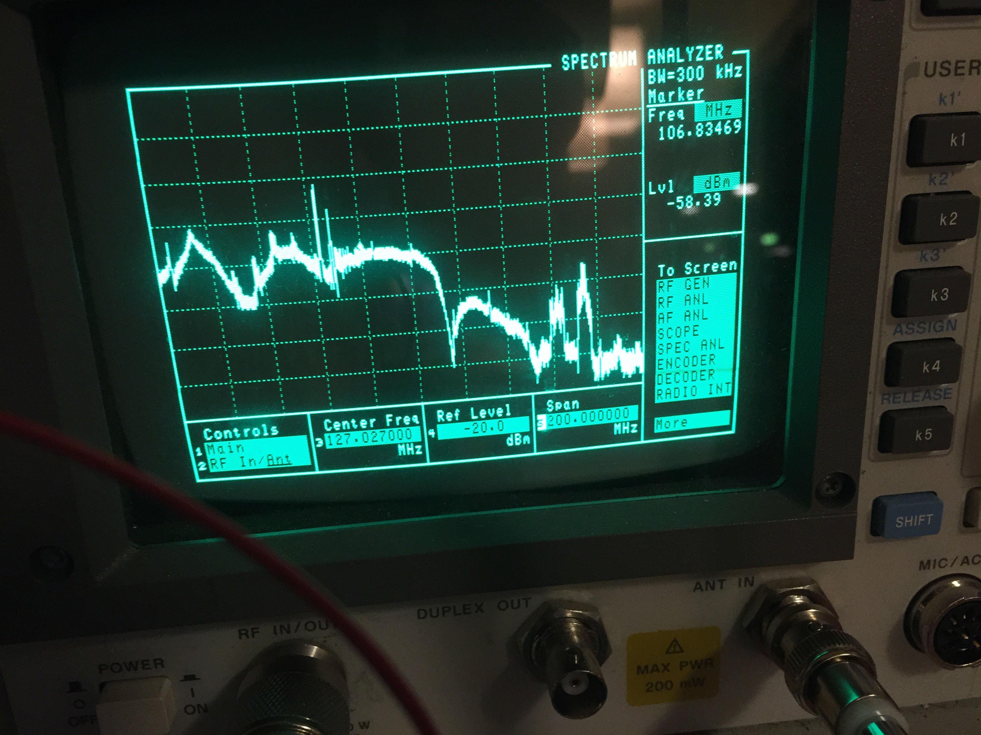
    Our spectrum analyzer only goes down to 10MHz, but as you can see, the Arduino PWM generated a ton of noise! The top of the spectrum analyzer is -20 dBm, so while we might have been in good shape, some of the harmonics in the LW and AM band were probably not in compliance.

    To fix this, I ordered some components to assemble a low pass filter off Digikey. Once these show up, I will demonstrate how well our spectrum has cleaned up!

    Also, for fun, I ordered some programmed crystal oscillators at some specific frequencies for all of the experimental bands (along with low pass filters). We can use the Arduino to turn this oscillator on and off with a GPIO pin, allowing us to use bands that are out of reach of the Arduino PWM to generate CW.

    Crystal oscillators are fun because they generate square waves when powered. These square waves can be surprisingly powerful. Driving a crystal oscillator at 12 volts can produce a quarter watt if you are not careful!

    Stay tuned for some Arduino PWM LowFER (160-190 KHz) and MedFER (525-1705 kHz) examples, along with some HiFER (13.56 MHz) and 49er (49.82-49.90 MHz) using these cool crystal oscillators.

    We did neglect one band that doesn't have a name yet (26.960 MHz - 27.280 MHz), but that falls within the CB band and might be a bit boring.

    Remember, these are all part 15 bands. Assuming you follow the rules, they are completely legal to use without a license. Thats right, you could potentially talk around the world without an amateur radio license. How weird is that?

  • Experimenting with "1 Minute" Antennas

    Casey Halverson07/22/2015 at 23:33 0 comments

    Antenna Introduction

    There are a ton of projects online that you can find for LF band antennas. These range from various loop antennas, random wire, inverted V style antennas, and countless other designs. You can even find some kite antennas! A great antenna has a resonance for the desired operating frequency, good SWR, and some gain to focus the energy to places we want it to go. Unfortunately, given the Part 15 restrictions and absurd wavelength of about 1 mile, we really can't do any of this. Most LowFERs make up for this deficiency on the receive side. The receive antenna can be unlimited in size, which is usually combined with a good receiver.

    After my last disaster of trying to make a "simple" Yagi antenna for 70 cm satellite work (my son uses the ruins of this poor Yagi project as swords now), I decided to see what could be done with a pair of wire strippers and some wire. Even a well built poster boy antenna will do poorly on the LF band, but lets see what antennas a loafing LowFER an accomplish without a trip to the hardware store, no parts, and no antenna matching. Or..... lets just pretend you are being held prisoner behind enemy lines, and they made the unfortunate decision of leaving an Arduino and some scrap wire in the cell....

    "1 Minute" Untuned Antenna Circuits

    The Jumper Antenna

    The Jumper Antenna was just one of those male/male jumper wires that are useful for breadboards. It wasn't very long, perhaps 4". It was connected to nothing on the other end.

    Results: Worked great on the kitchen table, but not much further than that.

    The Wire Antenna

    The FCC lets you use up to 50 feet of wire for an antenna. Lets stick the wire into one of the header pins and see what happens. To avoid a trip hazard, I just laid it on the floor. It was connected to nothing on the other end.

    Results: Not bad, but not all that great. It covered the house but not much more. The signal was considerably weak but better than the jumper wire I used.

    The Wire Antenna in a Loop

    Everyone seems to be on to something good with these loop antenna designs. Using the dining room chandelier as a support, I was able to construct a very crude loop antenna. The final end of the wire was connected to an unconnected pin on the same breadboard.

    Results: It actually improved over the long wire on the floor. I was able to receive it outside the front door. I suspect that there might be some weak coupling with ground taking place, making the radio circuit slightly more efficient.

    A Wire Loop Connected to Ground

    A word of warning: do not connect an untuned, unmatched antenna circuit directly to ground. This will damage your Arduino.

    Connecting a PWM pin to ground will force a relatively large amount of current to flow through the wire. Some of this energy will be radiated out. In order to avoid damage, I was able to rig up a 194 ohm resistor (100 + 47 + 47), which should limit the current to about 25 mA. We can get over 100mW flowing through this antenna.

    Results: If my Sony is anywhere near the loop, it overloads the receiver AGC. Wow. That was a big improvement. I can get about 100 feet now. If you just adhere to the Absolute Maximum Range (40mA), it does boost a bit -- but you risk burning out that pin.

    Wire Loop with 100 pF Decoupling Capacitor Connected to Ground

    Maybe blocking the DC component from generating heat into the resistor(s) will help? I will use a de-coupling capacitor (the 100pF I found in a drawer) and connect the other end of the loop to ground.

    Results: This significantly dropped the radiated power level worse than my basic wire antenna. If I disconnect the ground and touch the conductor, it does give the signal a slight boost...interesting. Besides our obvious antenna matching problem, a better ground system is going to help us improve later.

    Conclusion

    While some of these simple wire designs partially worked, we are going to need to do a little work to design a tuned antenna circuit.

    In the next update, we will take a look at the resonance circuit from an...

    Read more »

  • Experimentation with high speed PWM

    Casey Halverson07/22/2015 at 21:38 0 comments

    I have been experimenting with high speed PWM on the Arduino. After some exploring, I found a couple of libraries: http://madscientisthut.com/wordpress/daily-blog/16-bit-pwm-high-resolution-dc-source-on-an-arduino/

    I am currently using Sam Knight's library to generate PWM at 170,000 Hz, which seems to work just fine.

    For my first test, I connected a short wire (4") directly to the PWM line and placed it next to my Sony ICF-SW7600CR. I heard nothing on AM -- which is a good thing. After I switched it into SSB mode, I heard a CW tone! Using my fine tuning knob, I was able to raise and lower the tone's frequency. Tuning off frequency eliminated the tone, which I found a bit surprising. The PWM was remarkably clean with zero filtering.

    I looked around for harmonics. I found one on 340 KHz (Frequency * 2), but it was a bit weaker. I was unable to find one on 510 KHz and higher due to some very strong AM stations in my area.

    In order to comply with 20dB down from my carrier, and to play nice with everyone, this circuit is going to need a Low Pass Filter (LPF). This allows lower frequencies to pass unhindered, while attenuating higher frequencies. This will help squash this 340 KHz harmonic and anything up the band. There may also be some random spurs from the PWM signal that will also be attenuated, but I will not know what I am looking for until I put it on a spectrum analyzer.

    Now for a better antenna...

View all 3 project logs

Enjoy this project?

Share

Discussions

Radio Pushka wrote 09/01/2019 at 22:07 point

add a 50 ft wire and connect one of the GND pins to ground and enjoy your 10 miles of range.

  Are you sure? yes | no

Radio Pushka wrote 09/01/2019 at 21:55 point

I am planning to do the same thing, only I will use raspberry pis to send data and the arduino as an RF repeater with a nice solid 50 watt RF amp and a 200 watt ERP on 190 khz.

  Are you sure? yes | no

Similar Projects

Does this project spark your interest?

Become a member to follow this project and never miss any updates