 Tim
TimSTEM education is often talked about as something that needs to be improved and made more accessible. In recent years STEM has made newspaper headlines and become a political hot topic in the US. SAB3T offers a hands-on learning experience that is as equally suited for the class room as it for a tinkerer's desk.
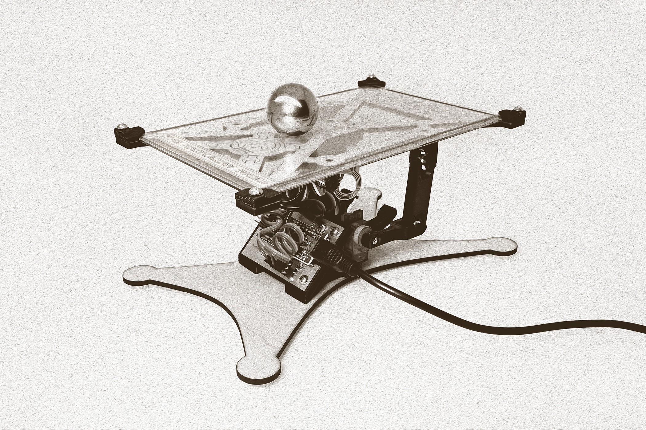
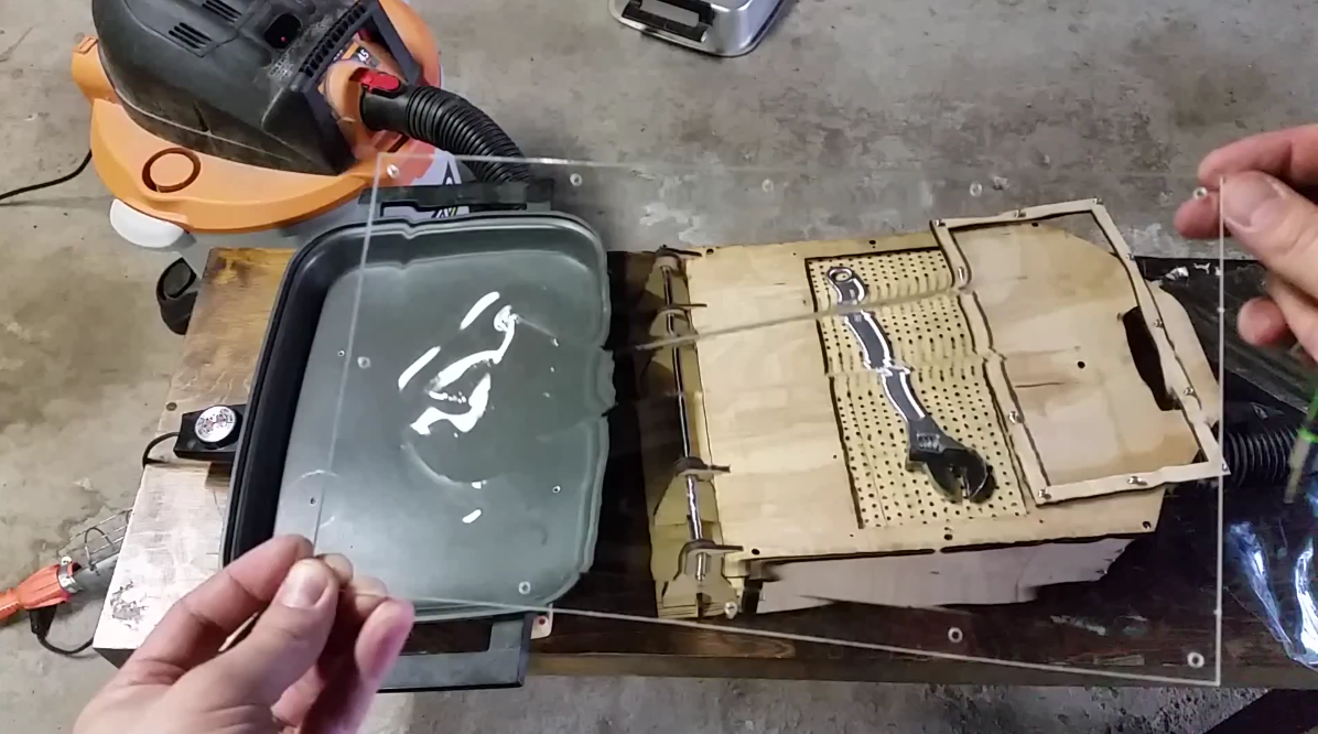
PID loops are a fascinating piece of engineering that are in use all around us. They move the nozzles in your inkjet printer, they keep quadcopters in sky, they keep your car cruising at 55; and with SAB3T they can balance a ball on a flat surface. They are so prevalent yet most people know little about them. With SAB3T you can watch the loop run and tune it in while viewing the actual PID data in real time. (Viewing data in real time requires a computer to run the python script)
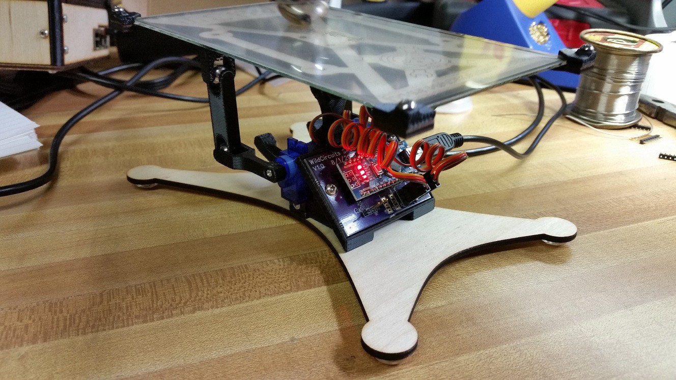
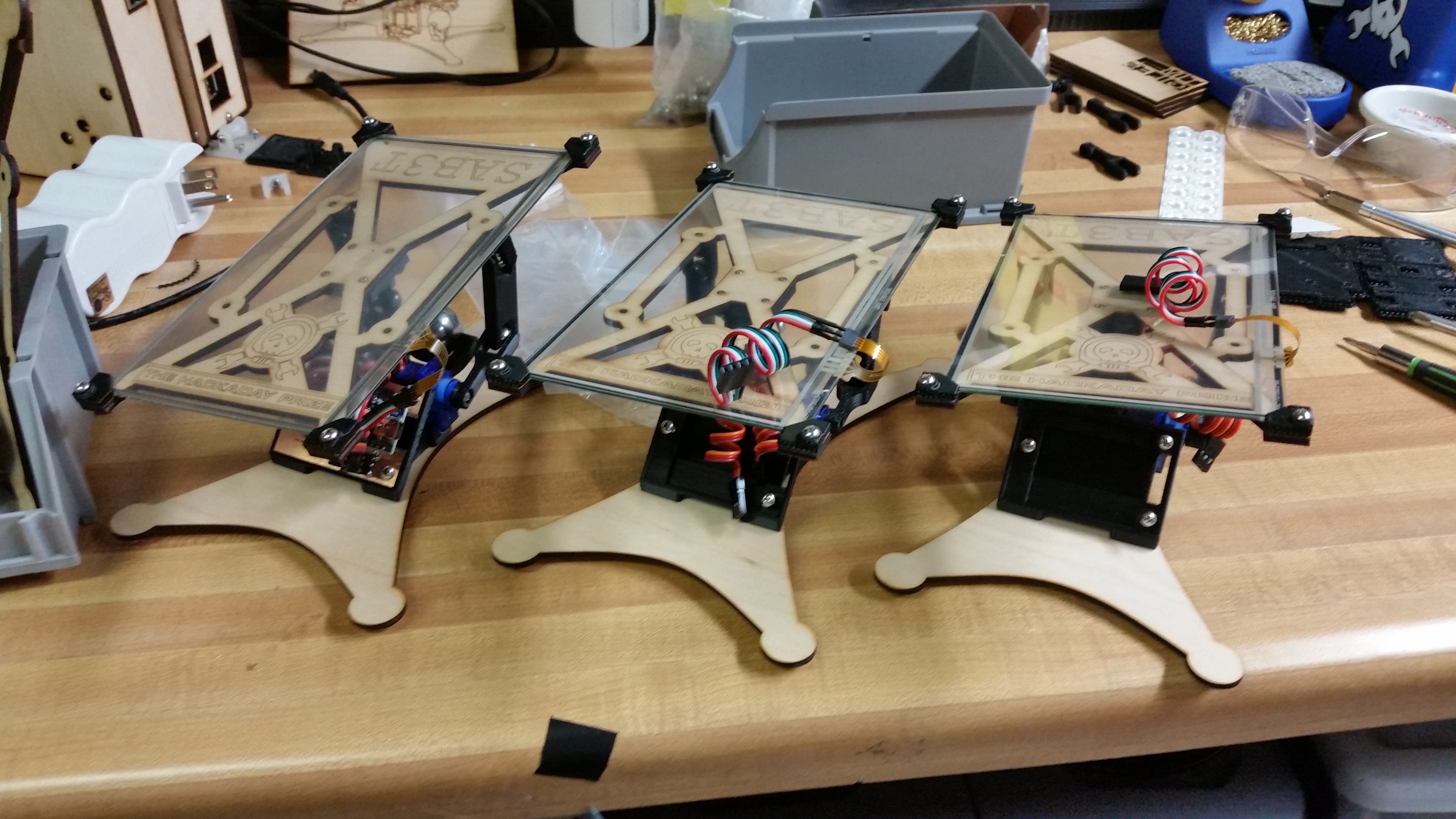
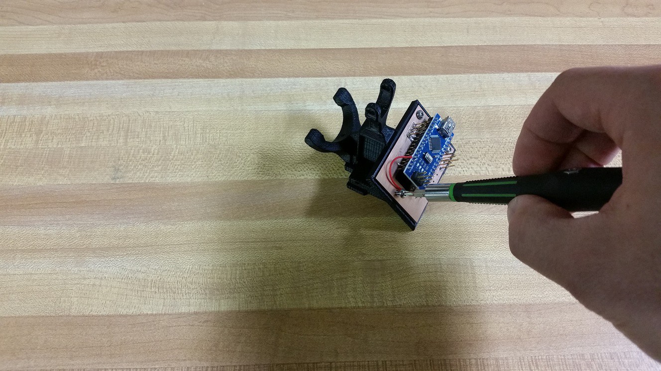
SAB3T will be sold as a kit to be assembled along with code examples and educational materials about the mathematics of control loops. Currently the SAB3T design is mechanically sound and functioning, working Arduino code is able to balance a ball bearing, and a python script is able to take data from the Arduino and live plot it.
SAB3T doing it's thing:
System Design Documentation
Electrical Connection Diagrams
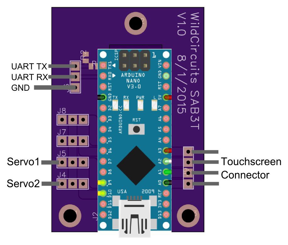
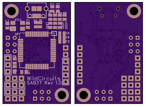
If you are building with the SAB3T PCB the following connection diagram applies:
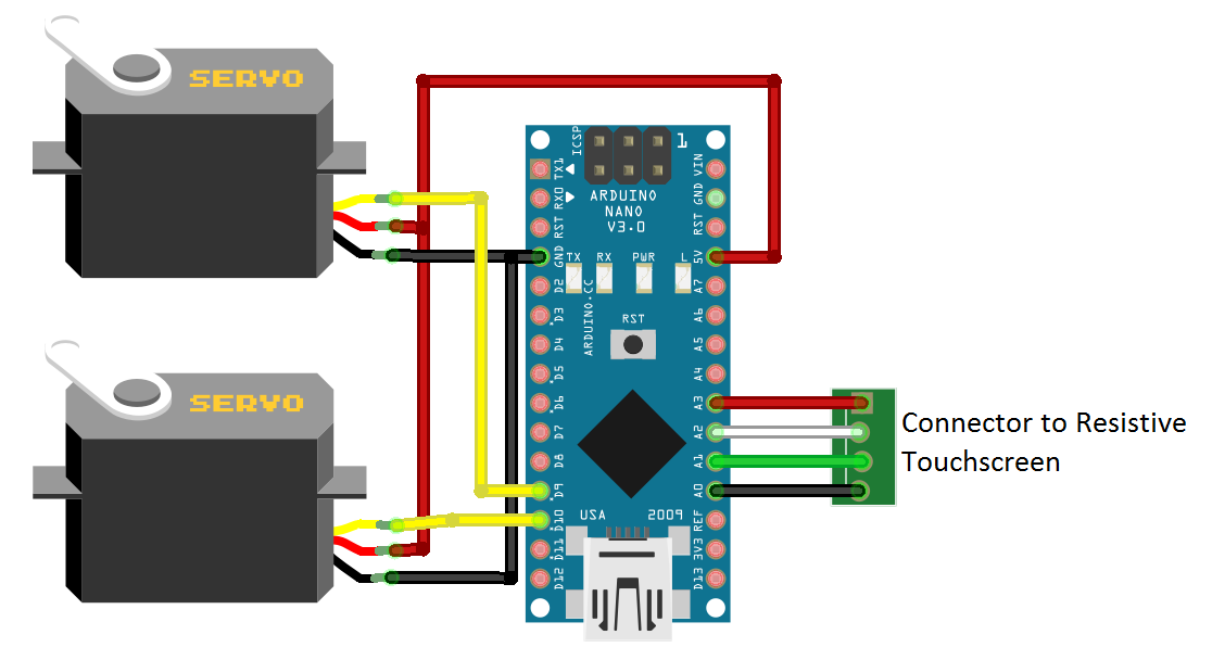
If you are building point to point with jumper wires then the following diagram applies:
Full build instructions are available below in the "Build Instructions" section
Example Arduino Code
Working code is available on the SAB3T github. Here are some of the features of SAB3T_PreProduction.ino:
- Initial servo position is stored in EEPROM
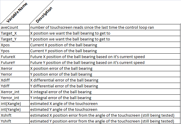
- All PID loop data is sent out the serial port to be graphed and studied. It is sent in a comma separated format after each control loop iteration
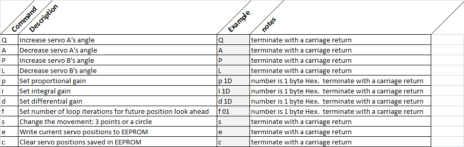
- A simple serial command interface has been implemented to allow live tuning of the control loop while it is balancing the ball bearing.
BalancerDisplay.py
This script requires python, pygame, and pyserial. I've tested it on Raspberry PI (Linux) and Windows.
There are 3 modes of operation: XY position graph, PID line graph, XY position overlaid on PID line graph. You can cycle through the modes by pressing "G" on your keyboard.
Updating PID parameters:
To update PID parameters, activate a parameter and use the "UP" and "DOWN" arrow keys on your keyboard to adjust the setting. You can activate a control parameter by typing it's letter.
"P" - proportional
"D" - differential
"I" - integral
When the PID line graph is active the traces can be turned on and off by pressing the number keys on the keyboard.
"1" - enable/disable position error
"2" - enable/disable differential error
"3" - enable/disable integral error
"4" - enable/disable touchscreen angle
"5" - enable/disable X/Y shift from touchscreen angle
Setting the level point:
Press the "E" key when the touchscreen is level to overwrite the servo start points in the EEPROM.
Website
I bought SAB3T.com. Right now it just redirects to my Build Instruction here on hackaday.io. I'd like to make that website into a central point of information for SAB3T, including tutorials, code and a forum for users to share.
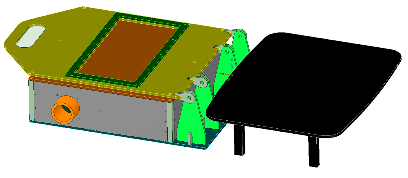
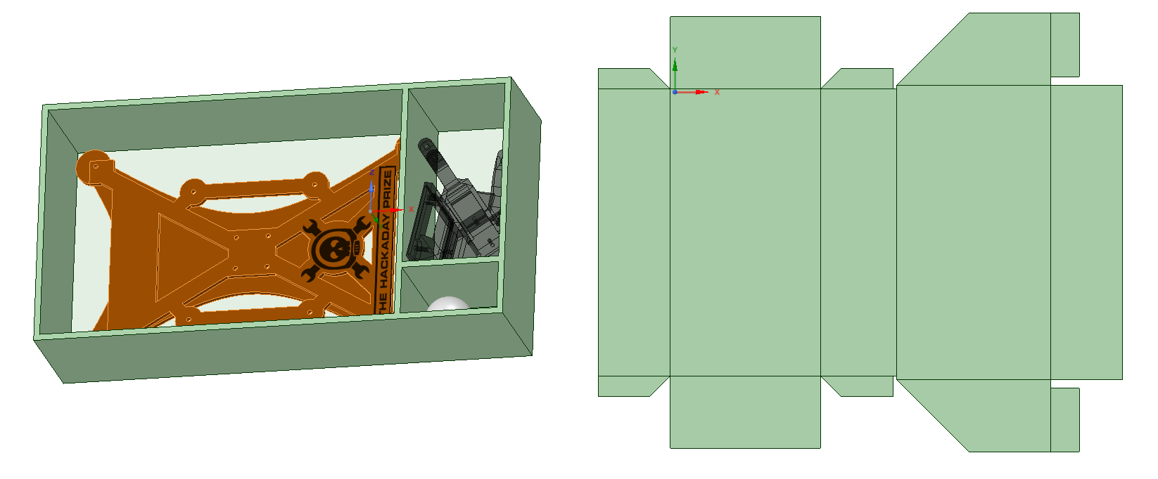
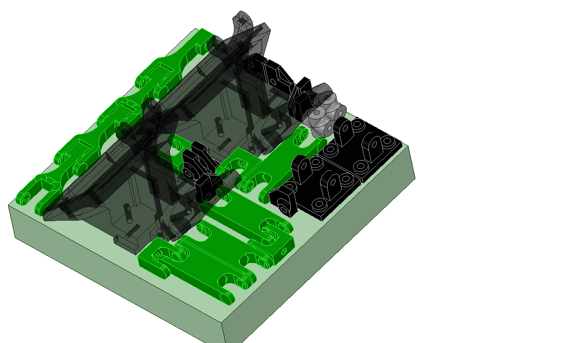
Artists Rendering of Productized Look and Feel
What's Next
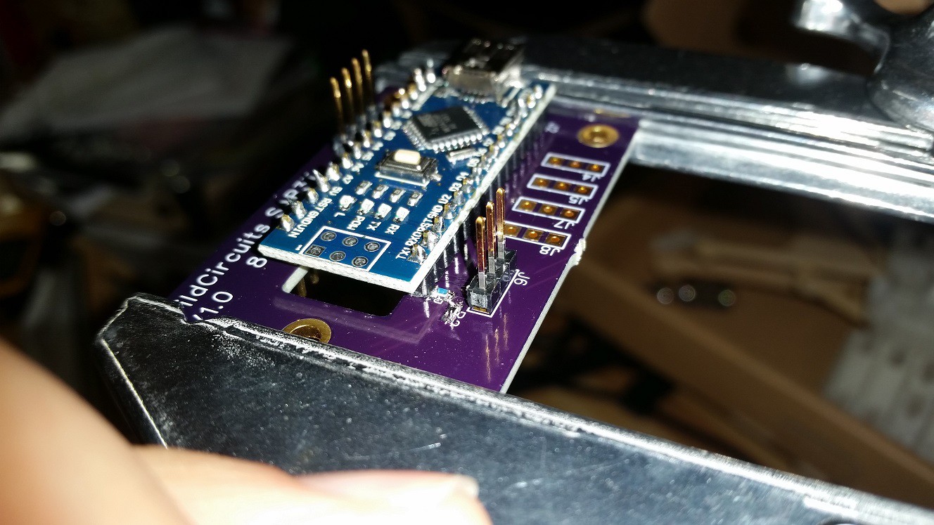
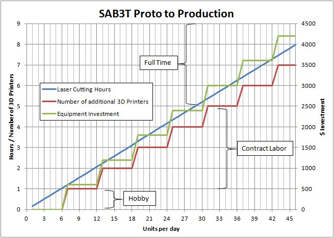
PCB rev 2: Instead of an Arduino Nano breakout board I want to create a custom Arduino compatible board that is small and has the appropriate connections for SAB3T. I need to study the cost of this approach and figure out at what volume a custom board like that will make financial sense. Bringing SAB3T to market with a fully custom Arduino might take a crowd funding campaign to hit some order requirements.
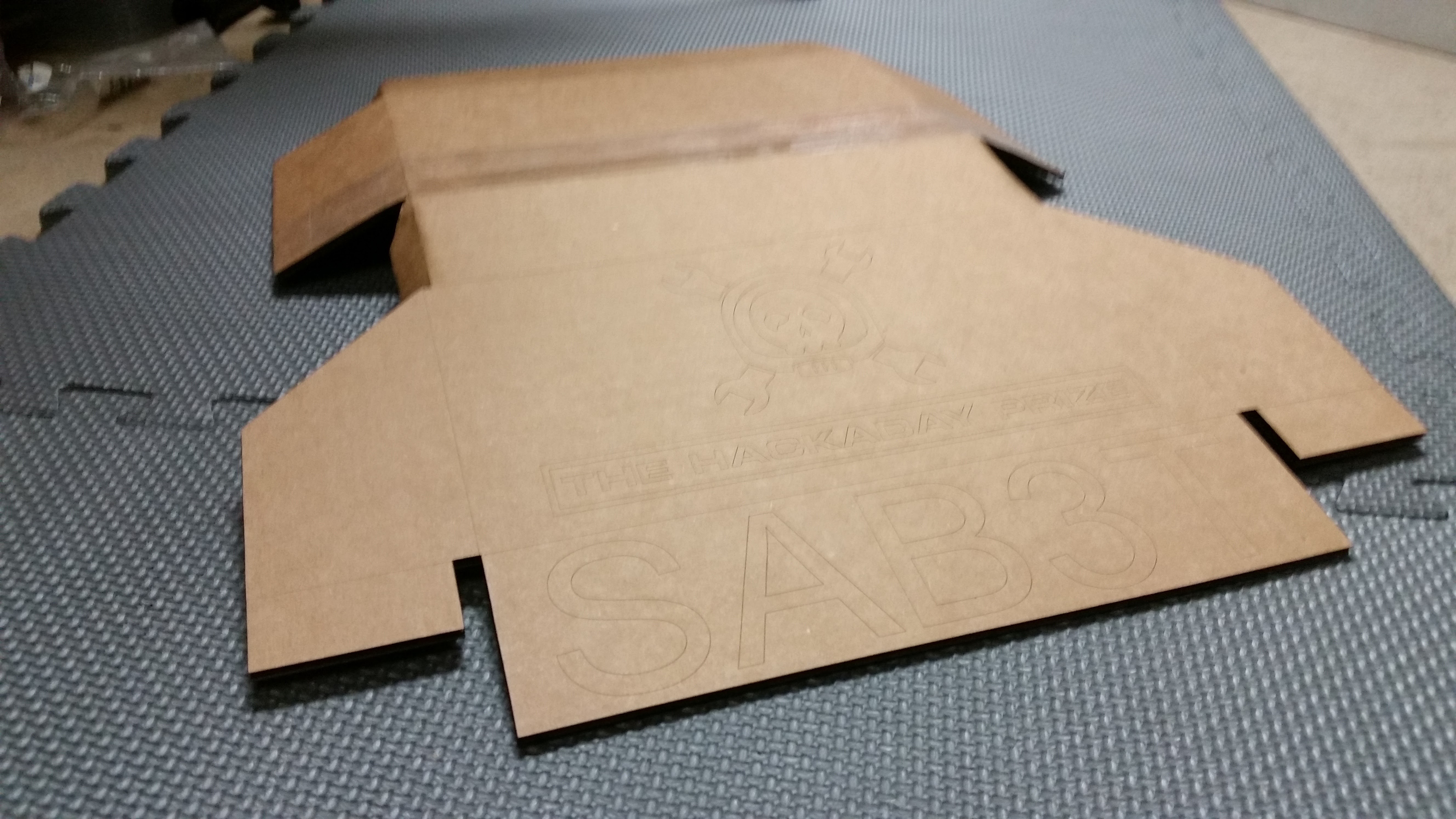
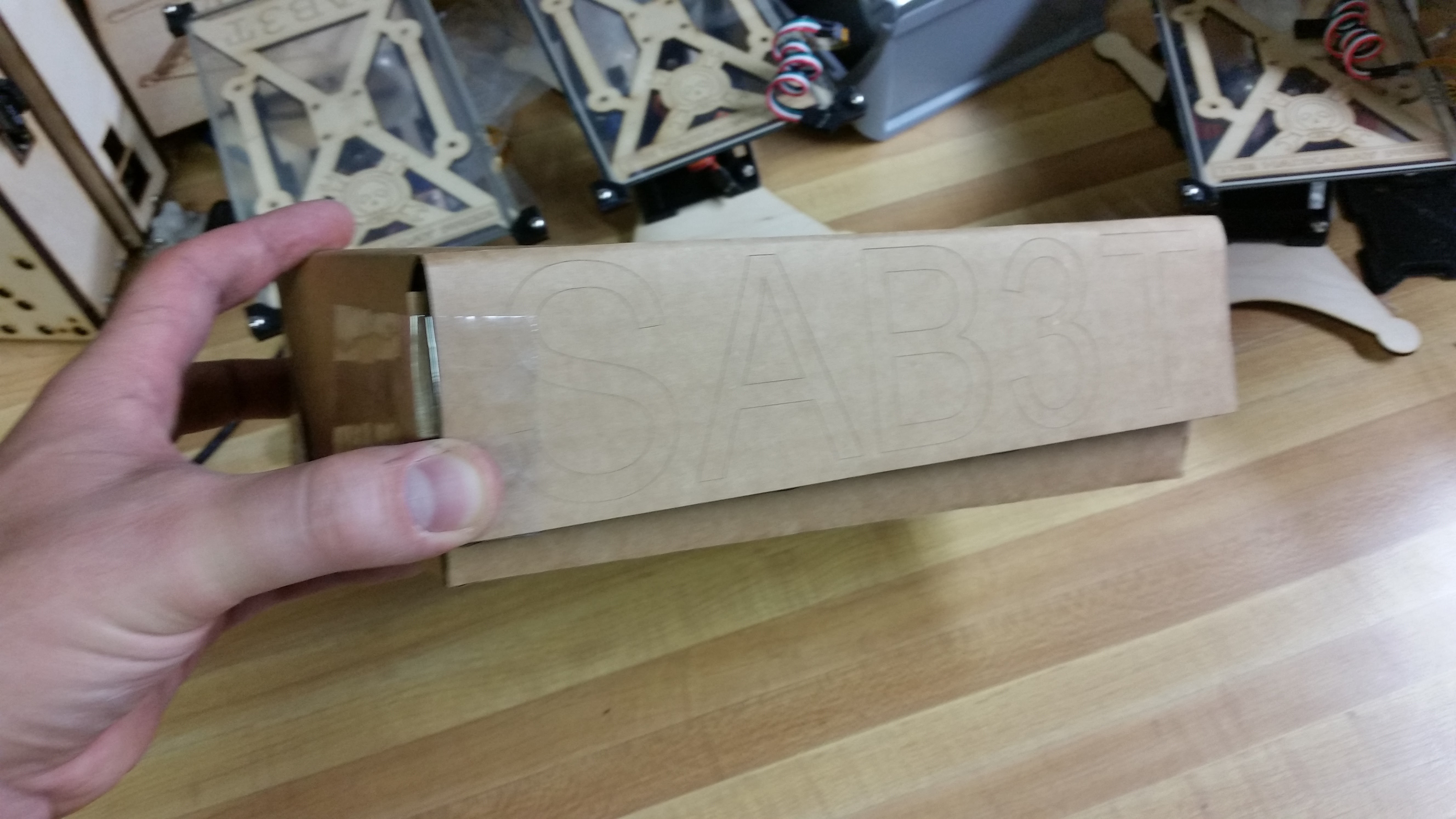
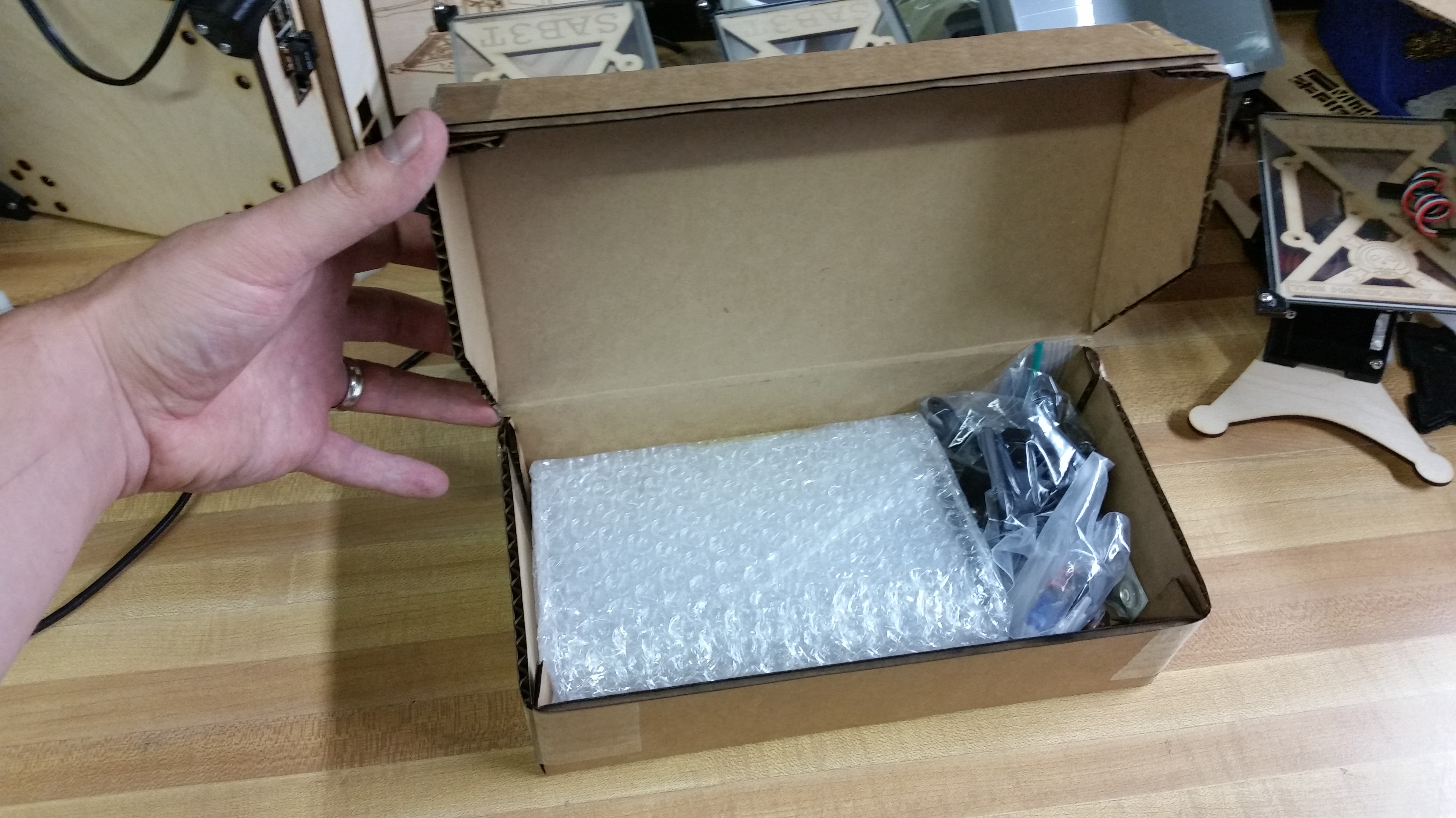
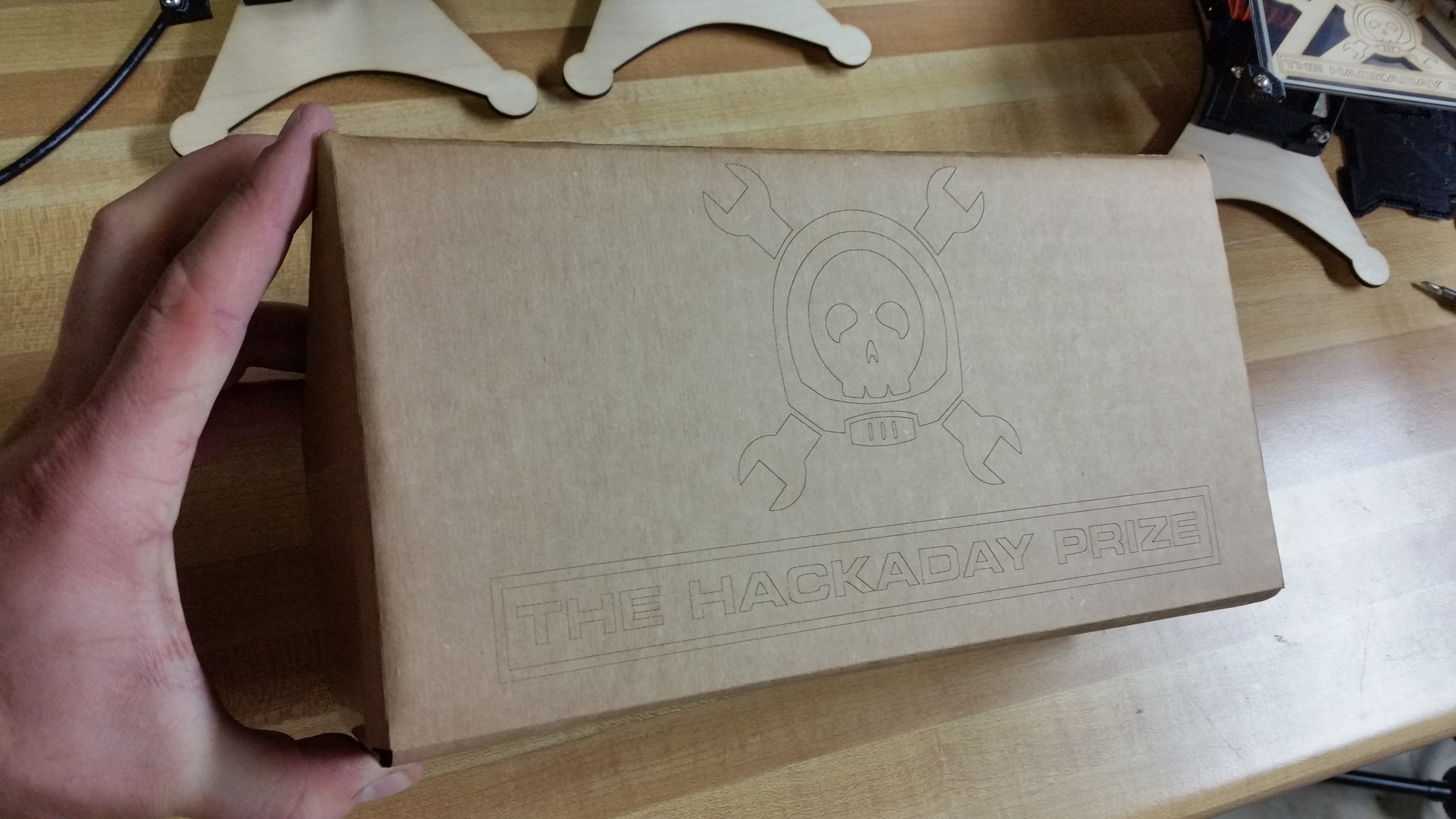
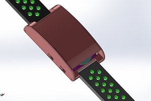
Retail Packaging: I want to explore unique packaging options. I want it to be sleek and cool and functional. My first attempt ended up being a regular old box with some engraving on it.
Educational Material: I've positioned SAB3T well to be useful educational tool. Now I need to create some supplementary educational stuff.
Licenses
All hardware and software is licensed under "Creative Commons - Attribution...
Read more »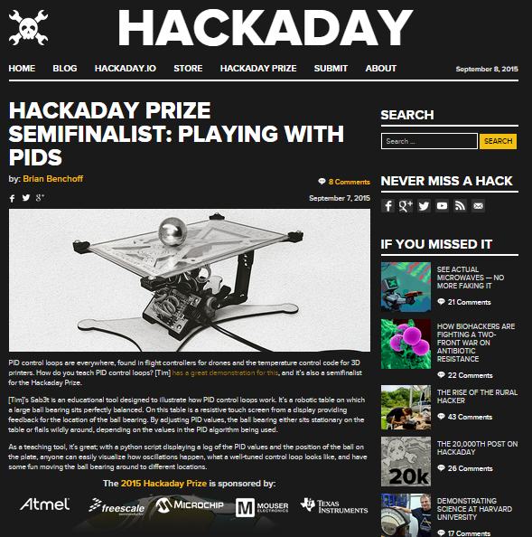


 Chaz
Chaz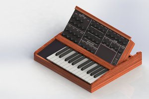
 T. B. Trzepacz
 barb
barb
 Giovanni
Thanks for providing us this great knowledge, I love the green space so visit automatic washing machine