charliex
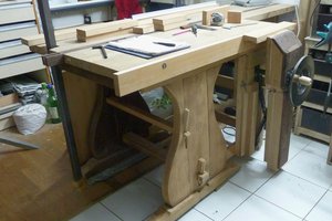
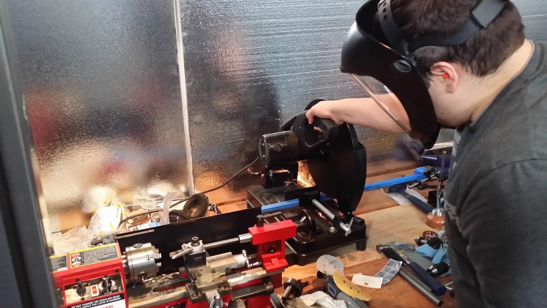
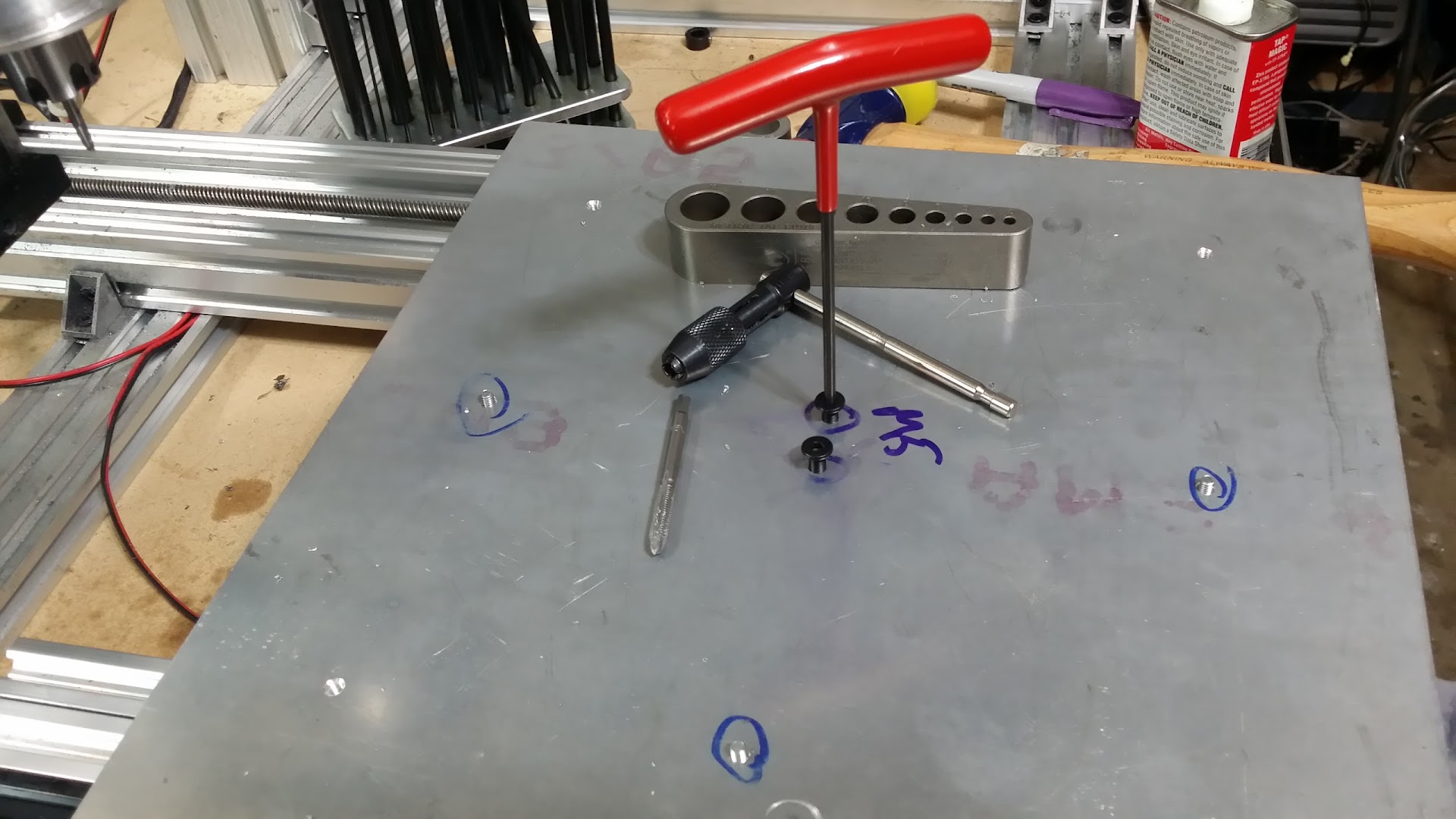
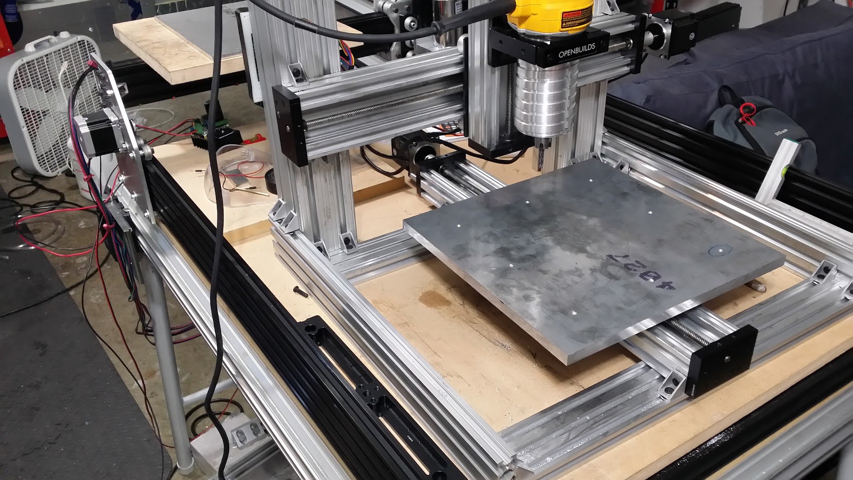
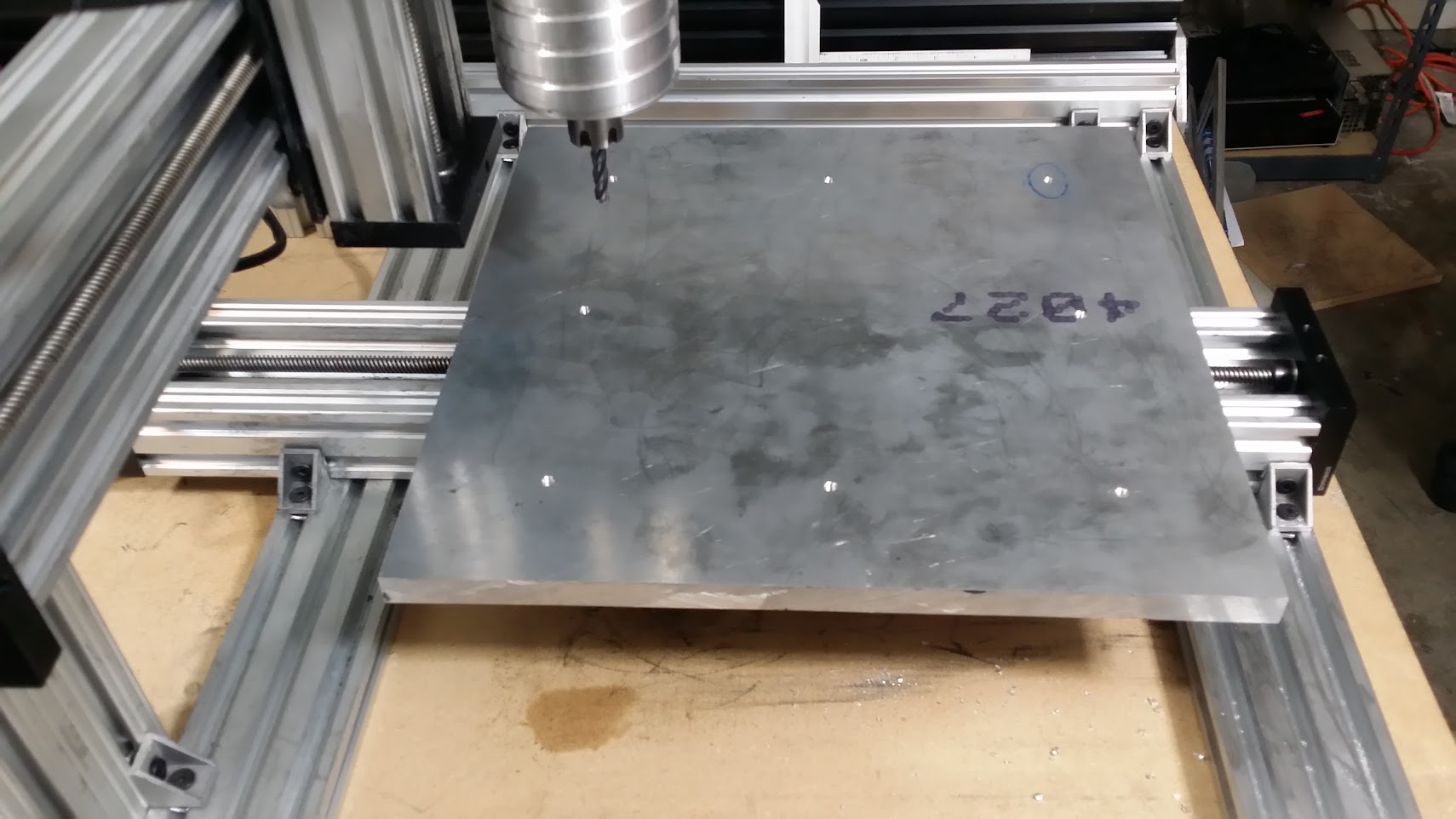
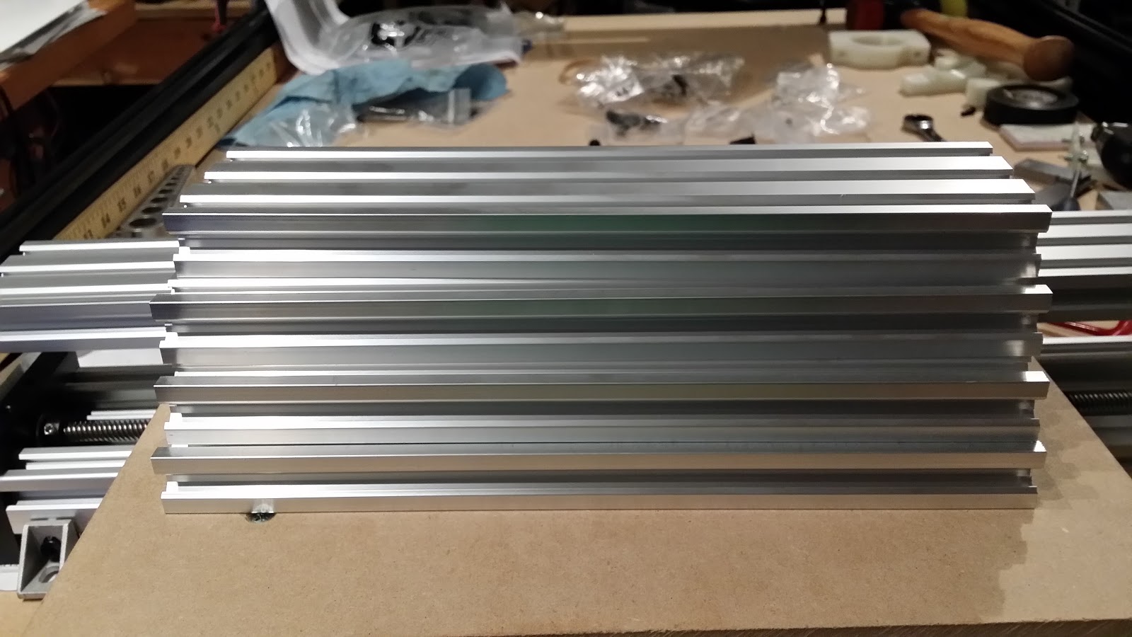
A machine designed to make end plates etc for other CNC machines, and various other plate designs.
0%
0%
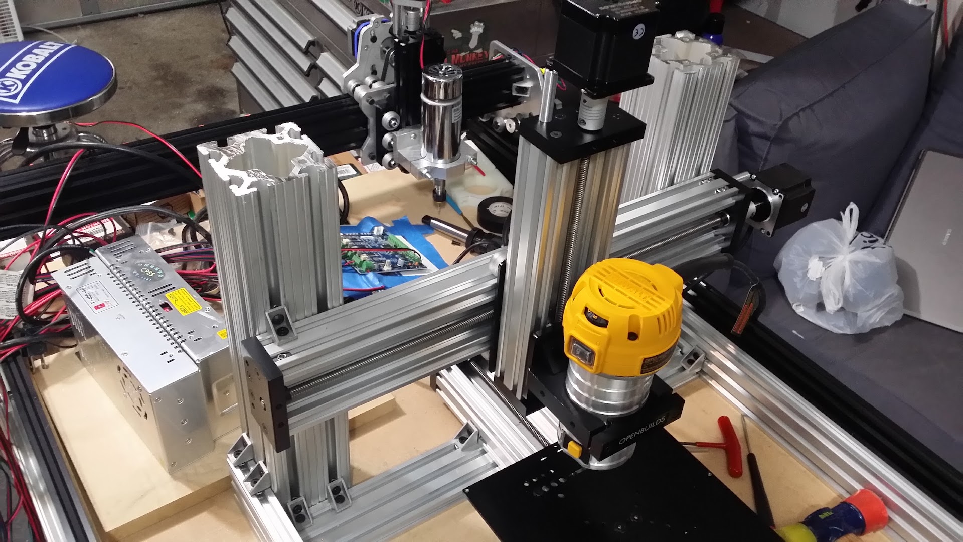
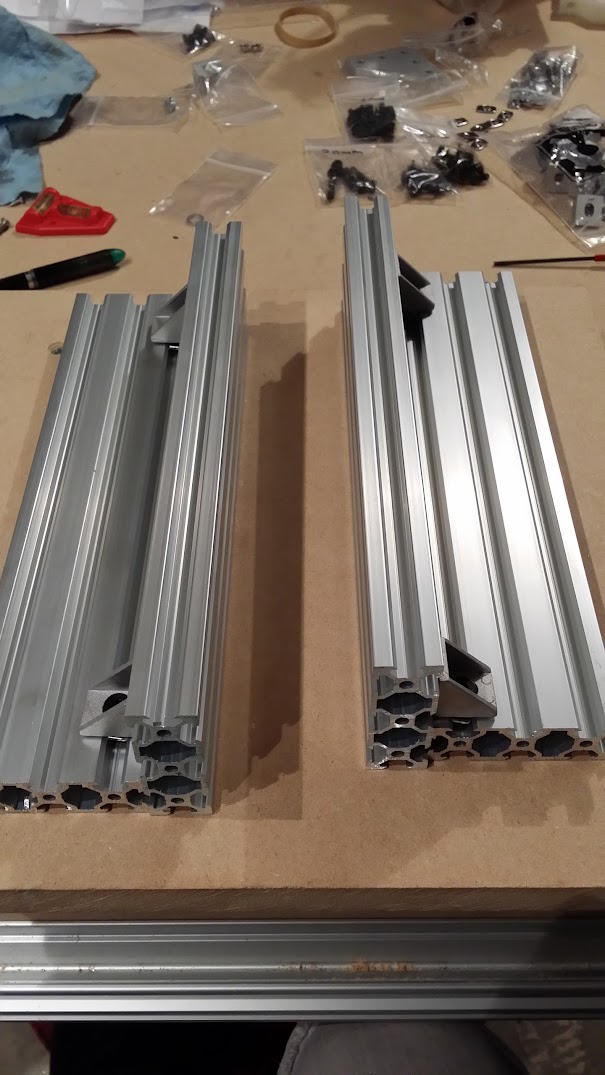
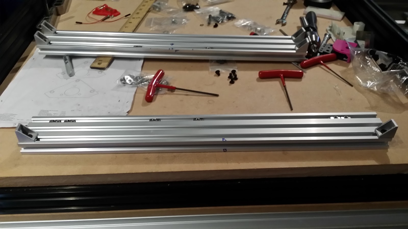
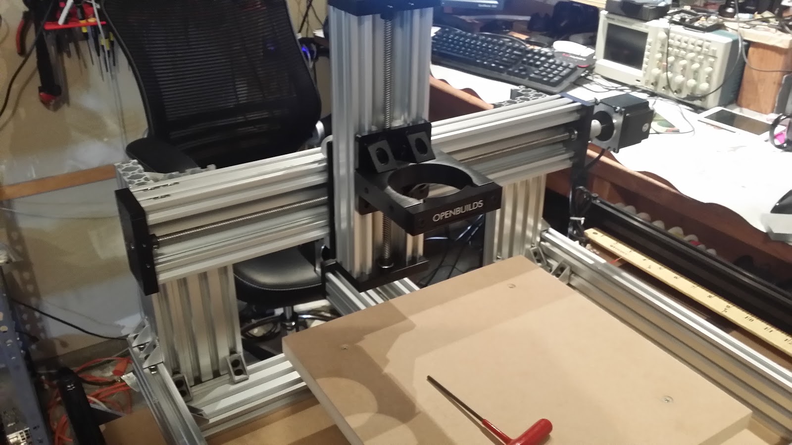
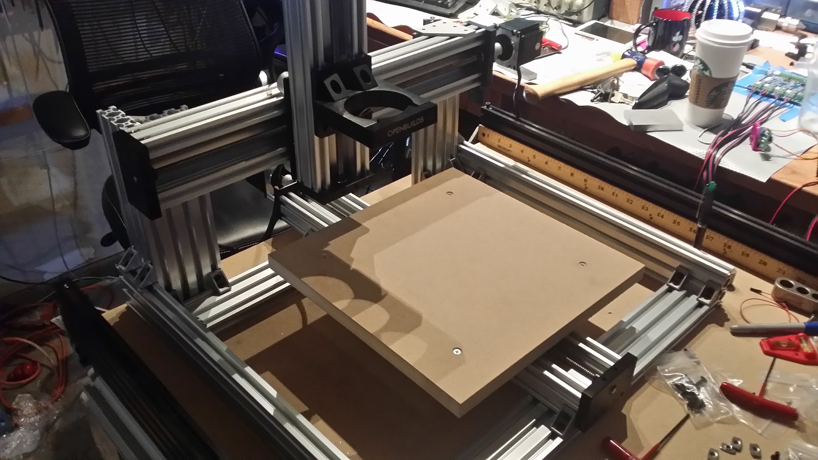
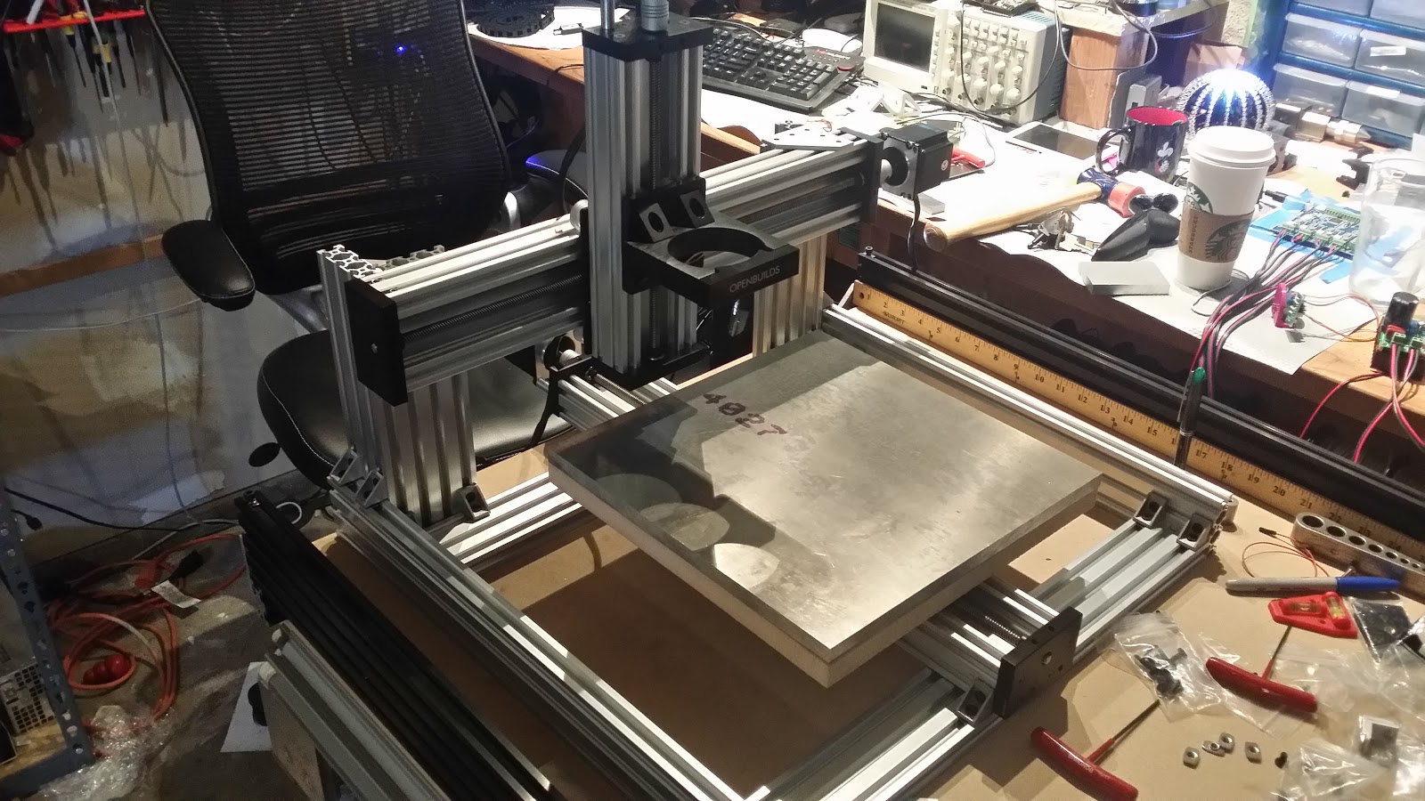
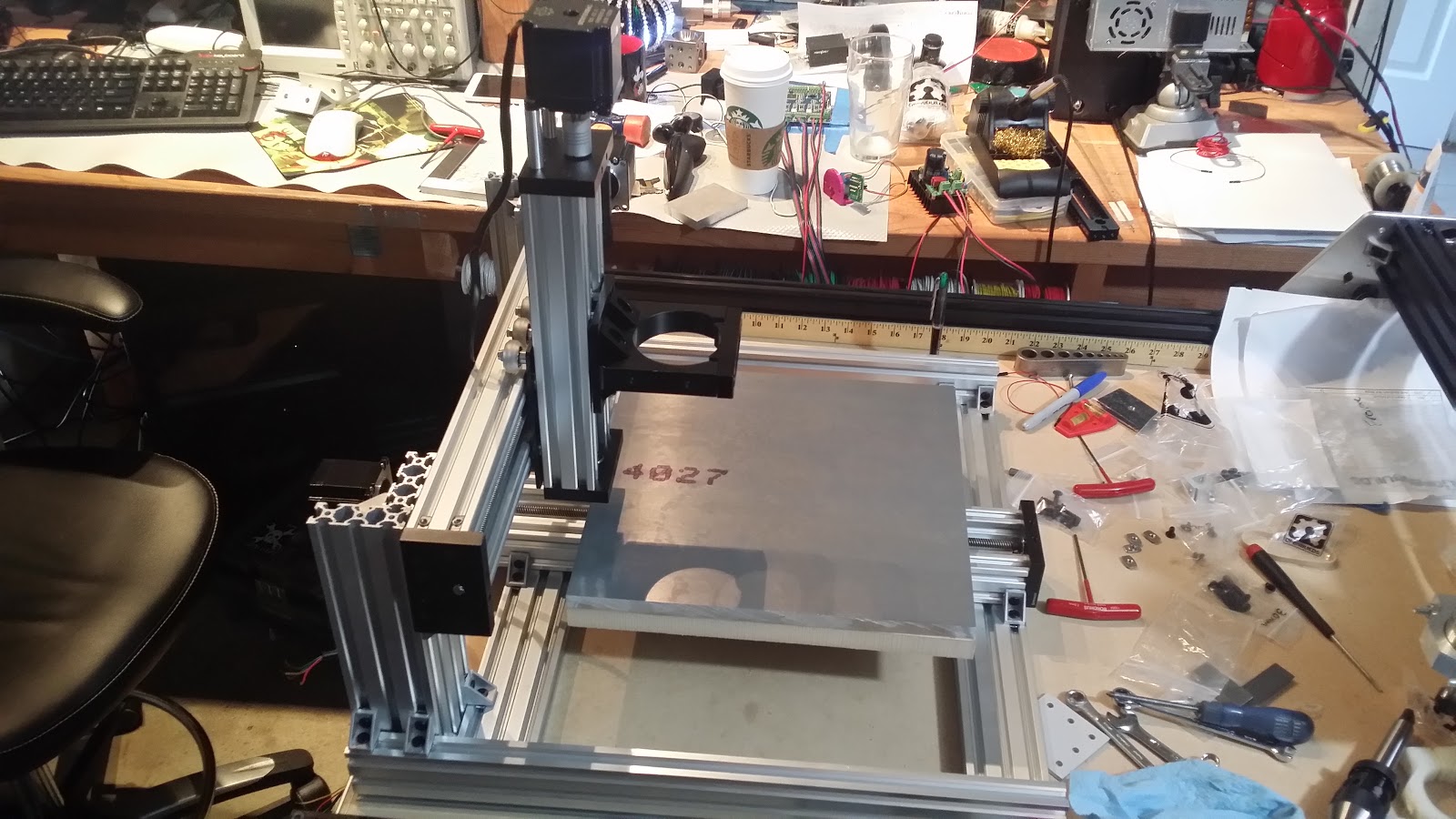
OpenBuilds C-Beam™ Machine Build
C-Beam Machine is a CNC machine design based on the popular V-Slot linear guide system.
Become a Hackaday.io member
Already have an account? Log in.
Just one more thing
To make the experience fit your profile, pick a username and tell us what interests you.
Pick an awesome username
hackaday.io/
Your profile's URL: hackaday.io/username. Max 25 alphanumeric characters.
Pick a few interests
Projects that share your interests
People that share your interests
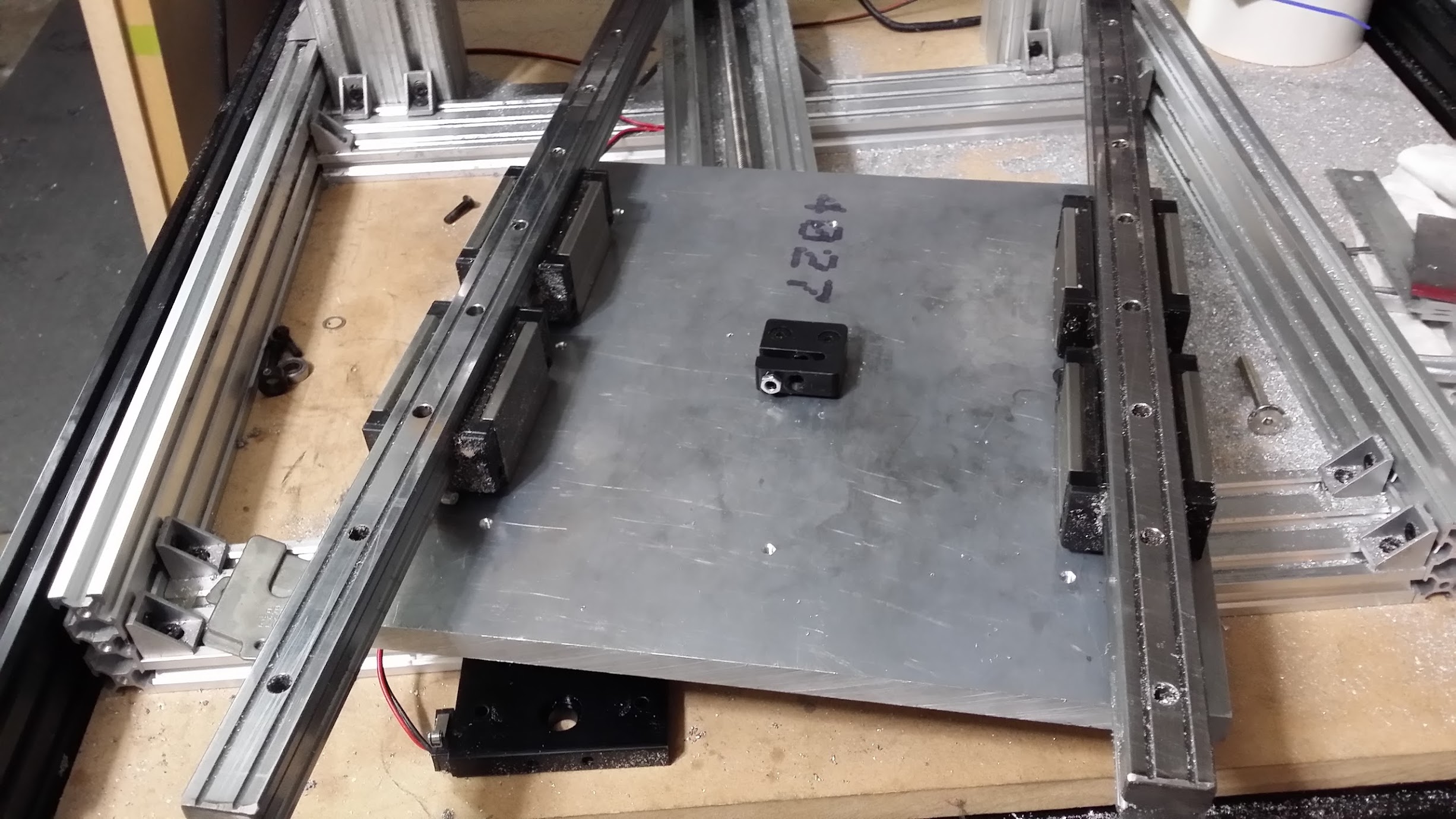
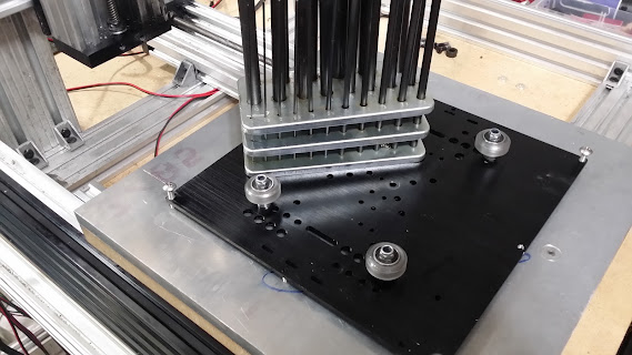
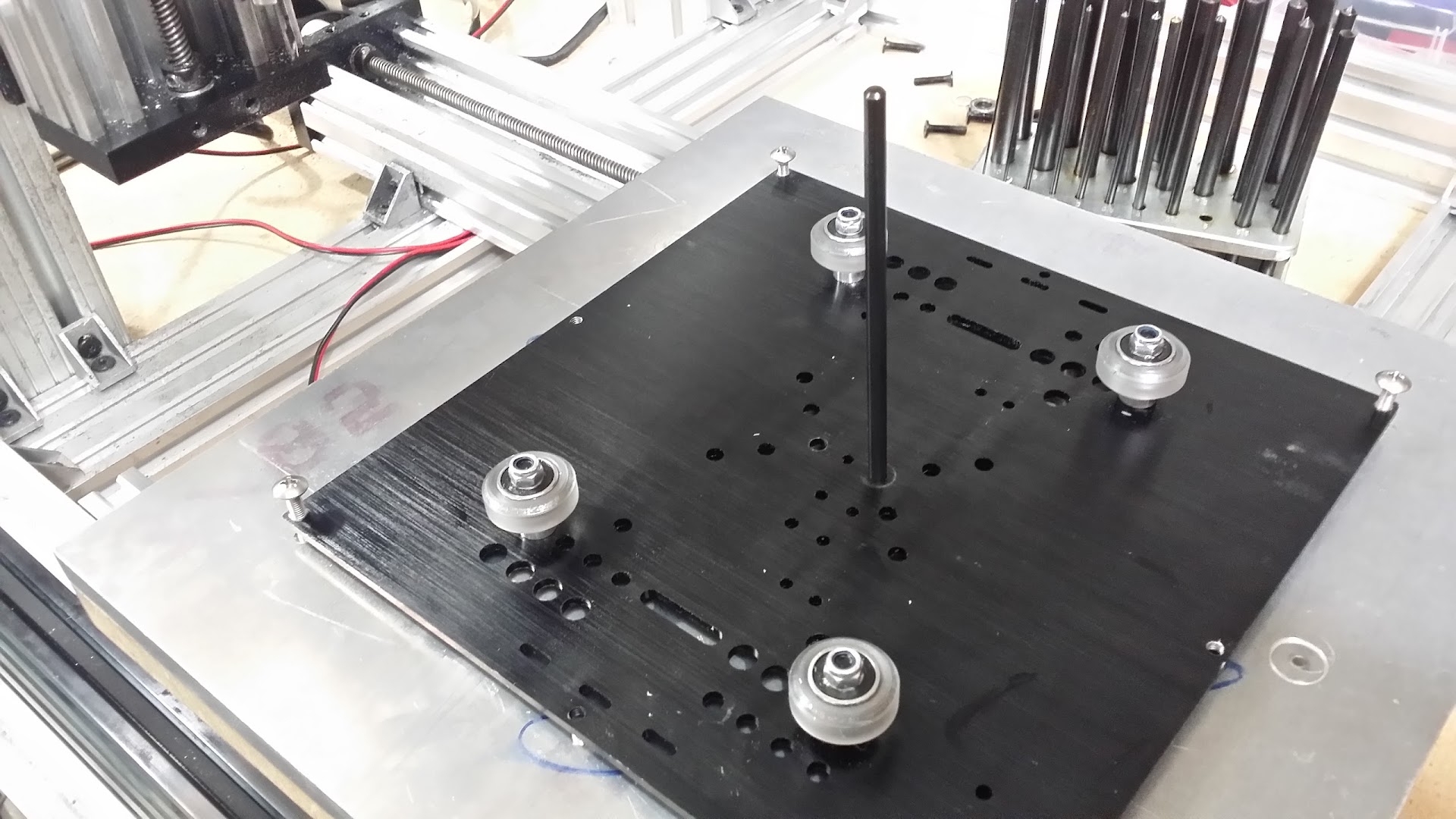
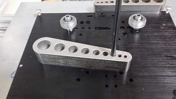
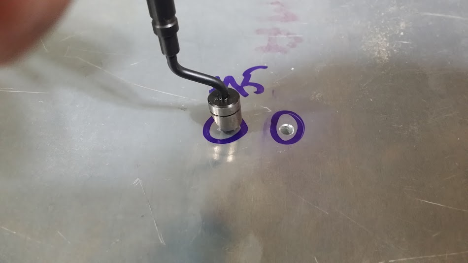
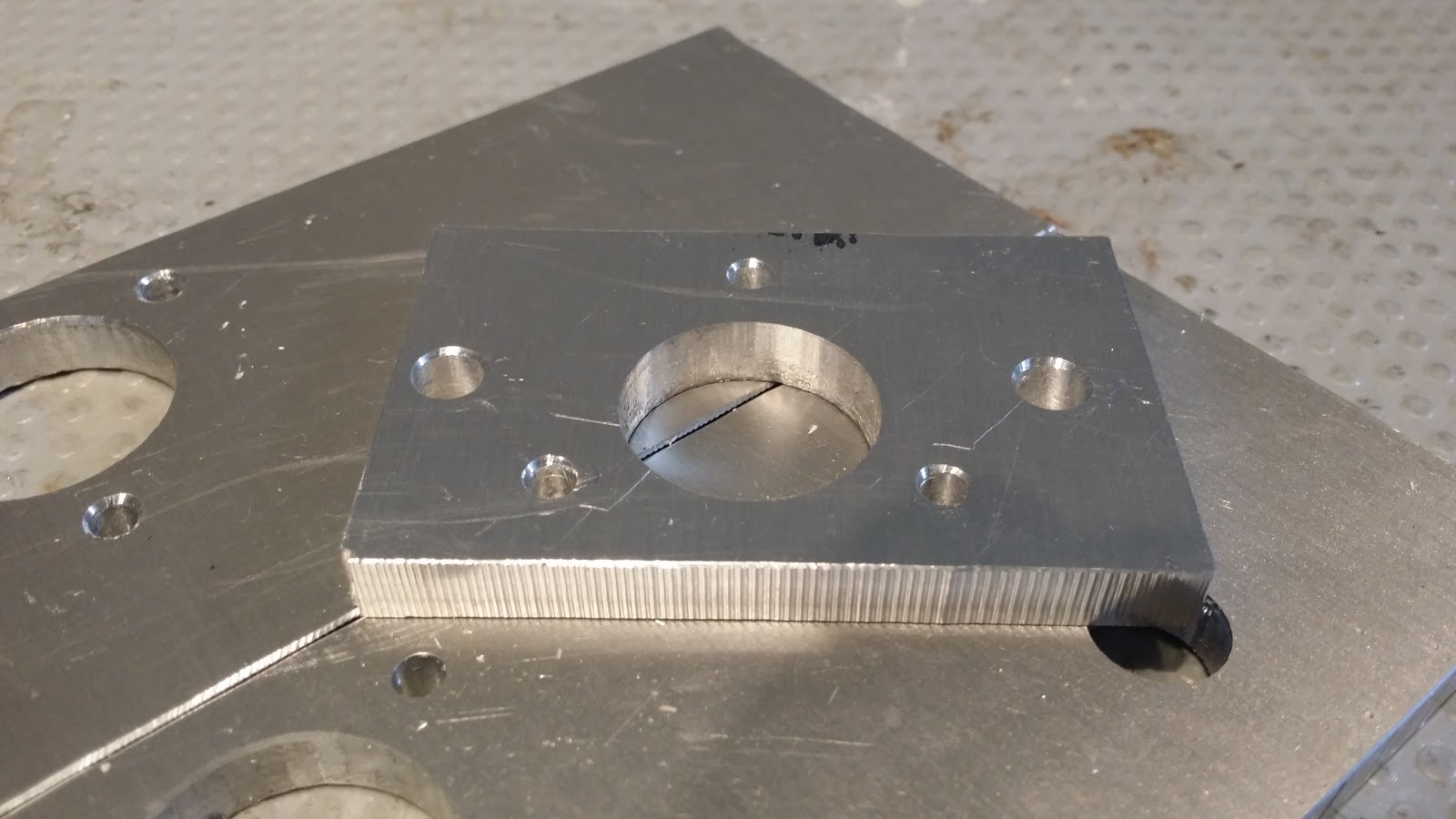
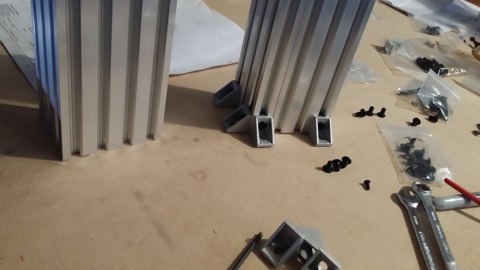
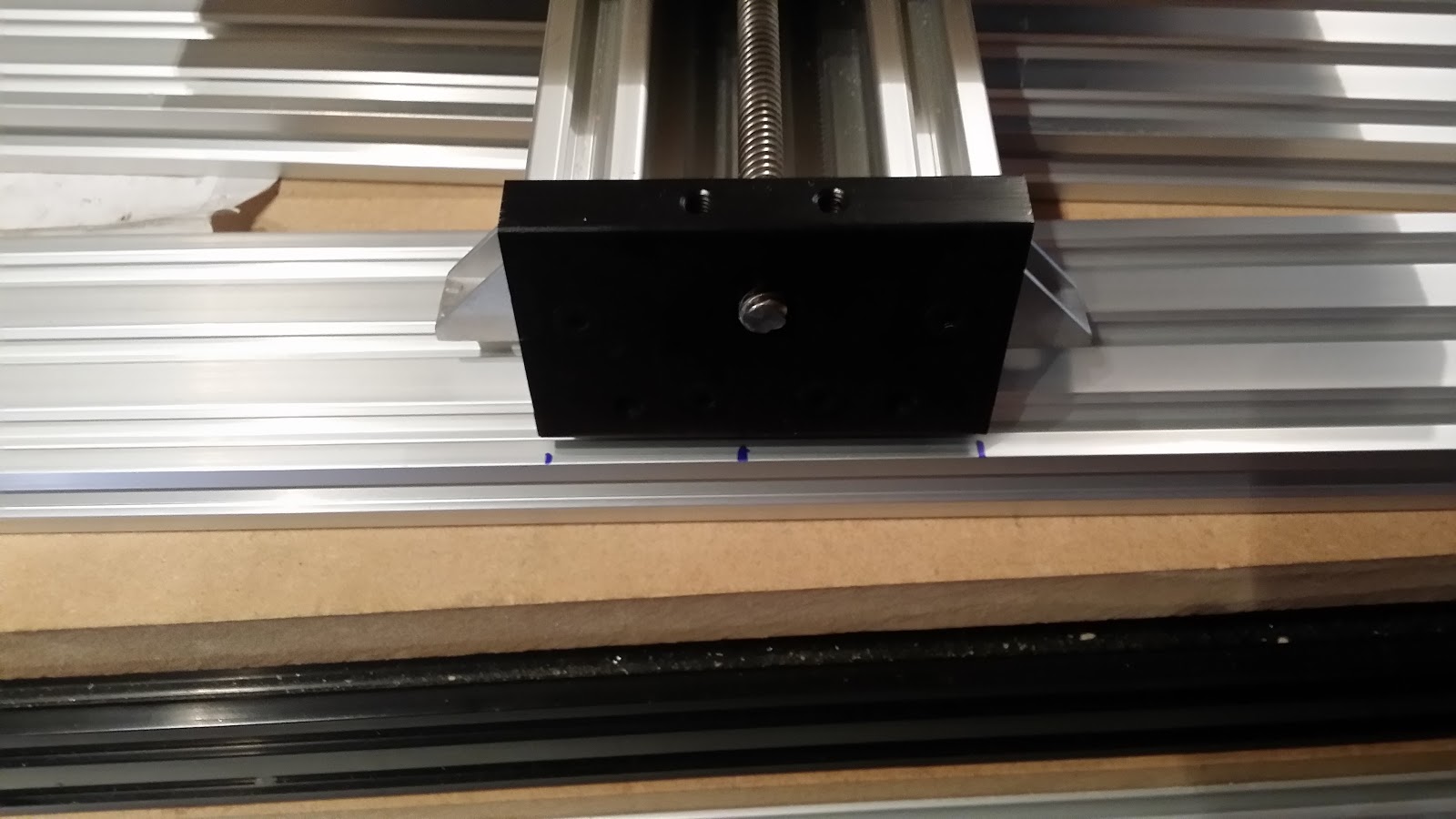
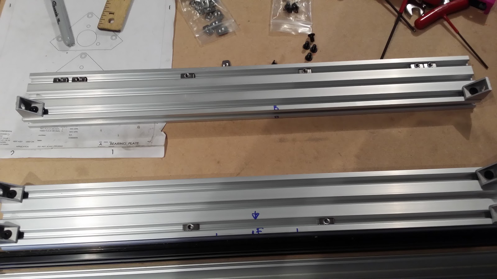
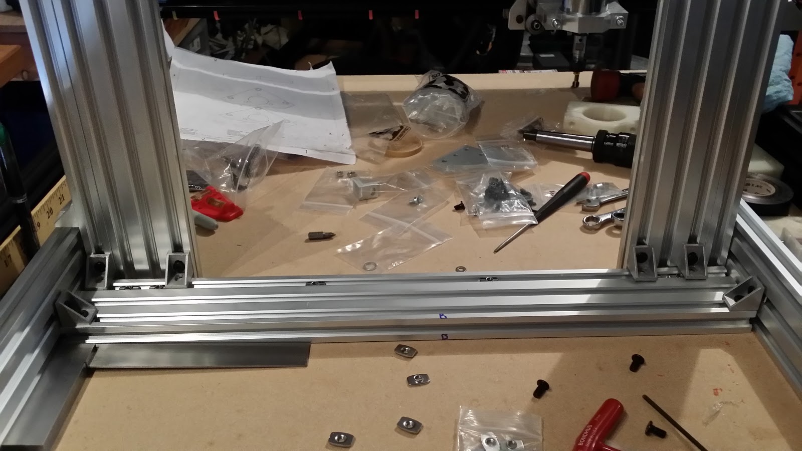
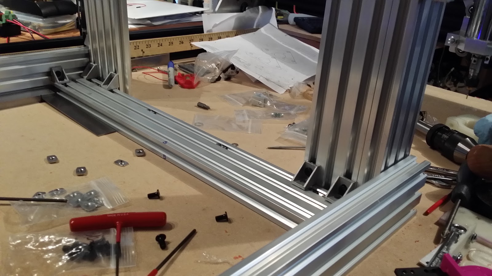
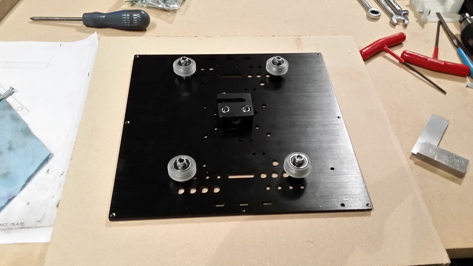
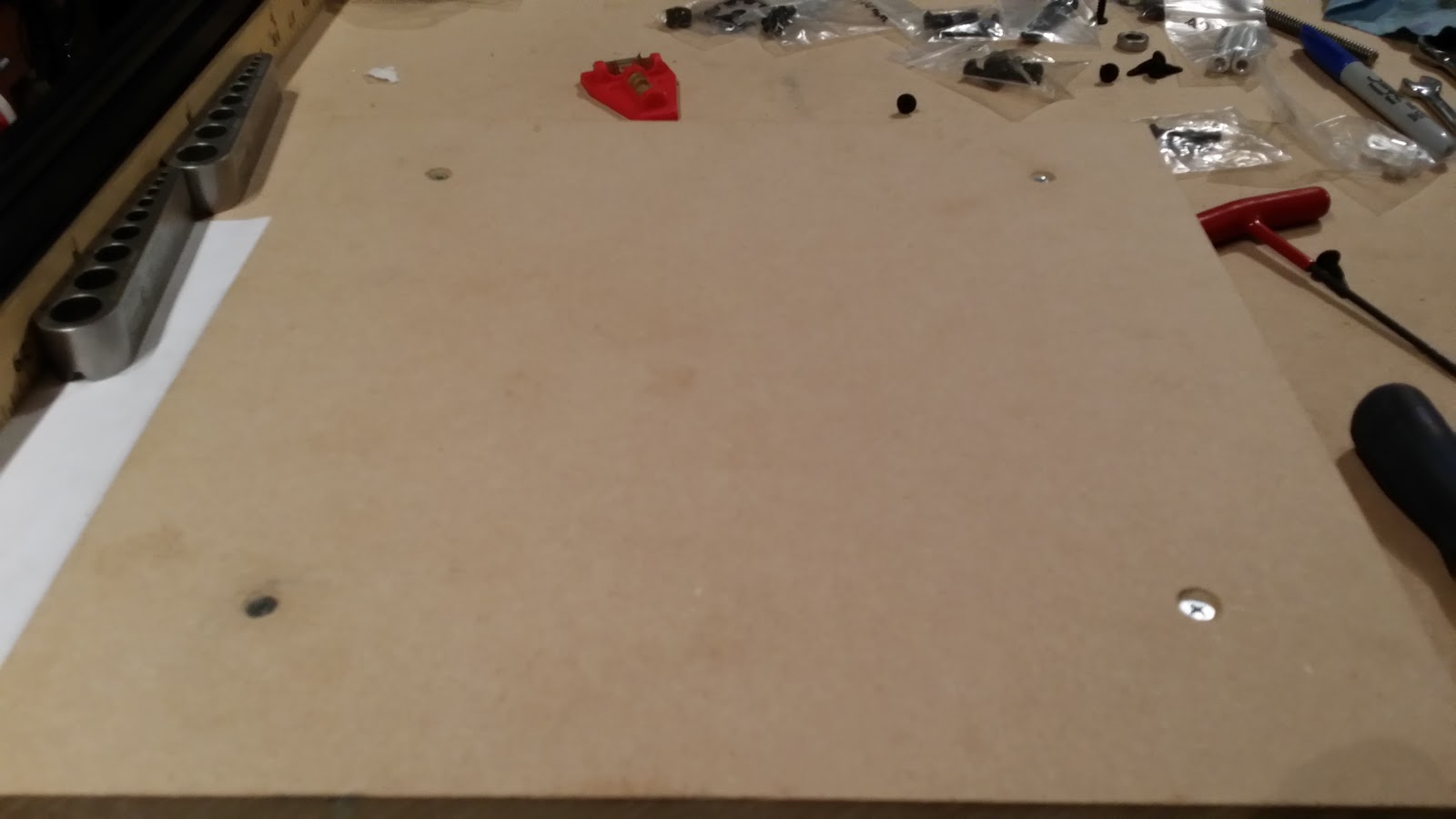
 mounted the nut
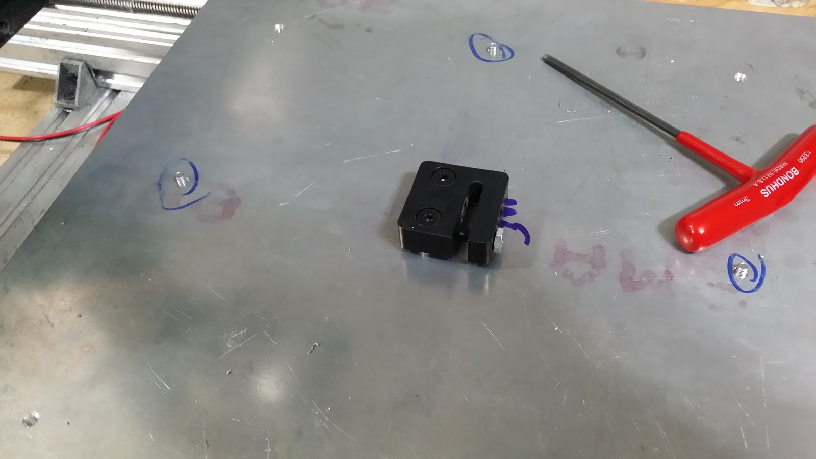
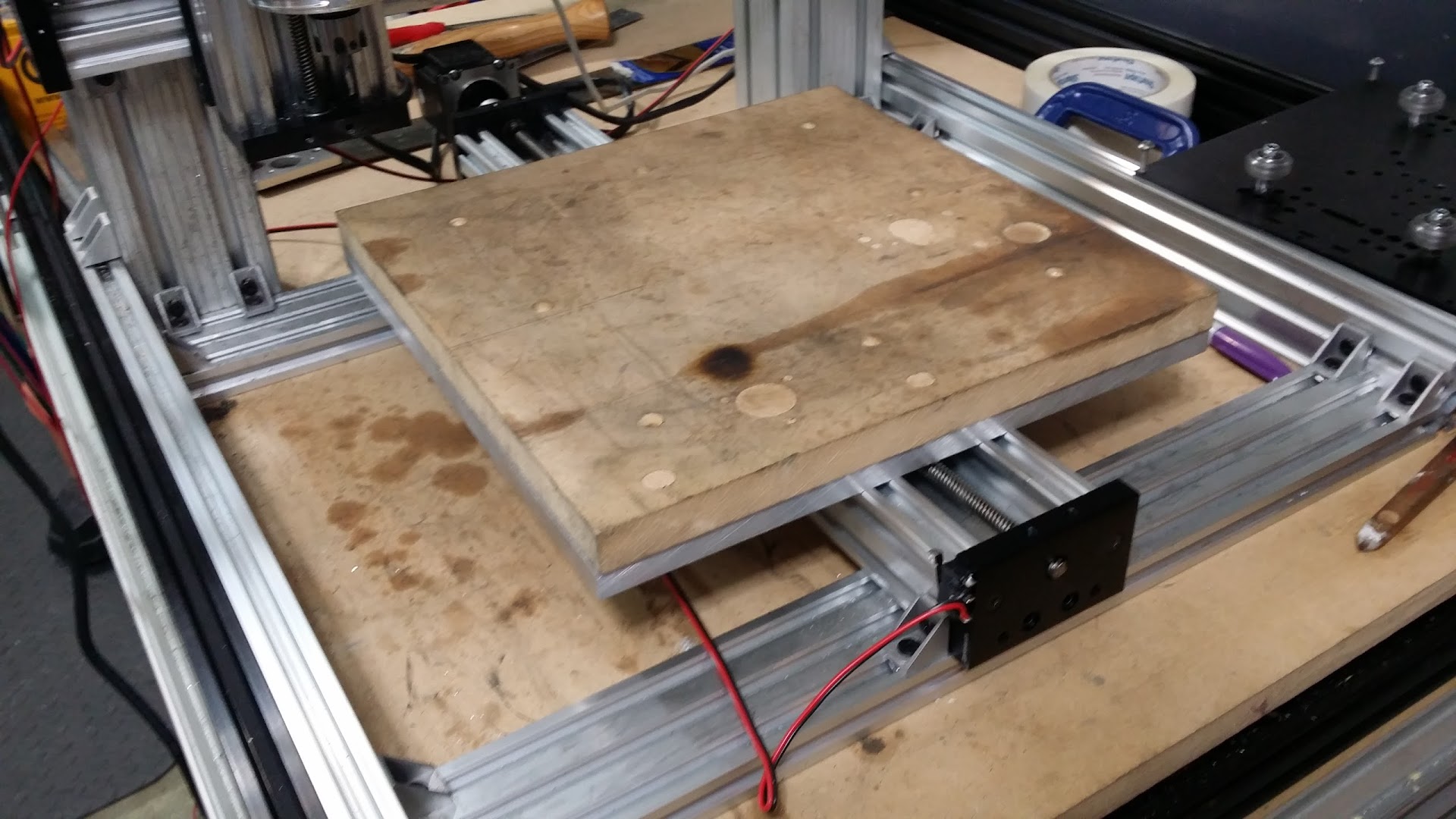
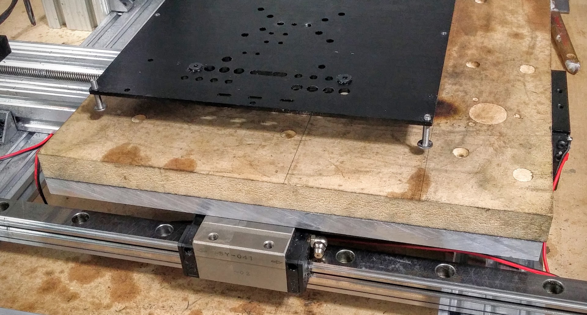
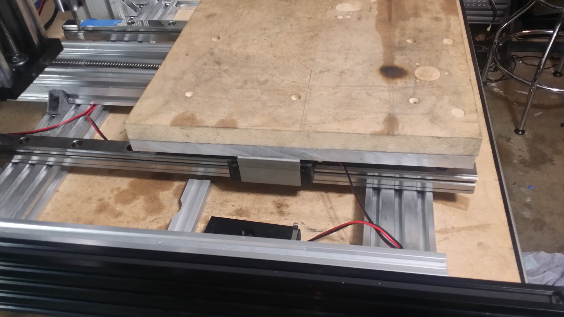
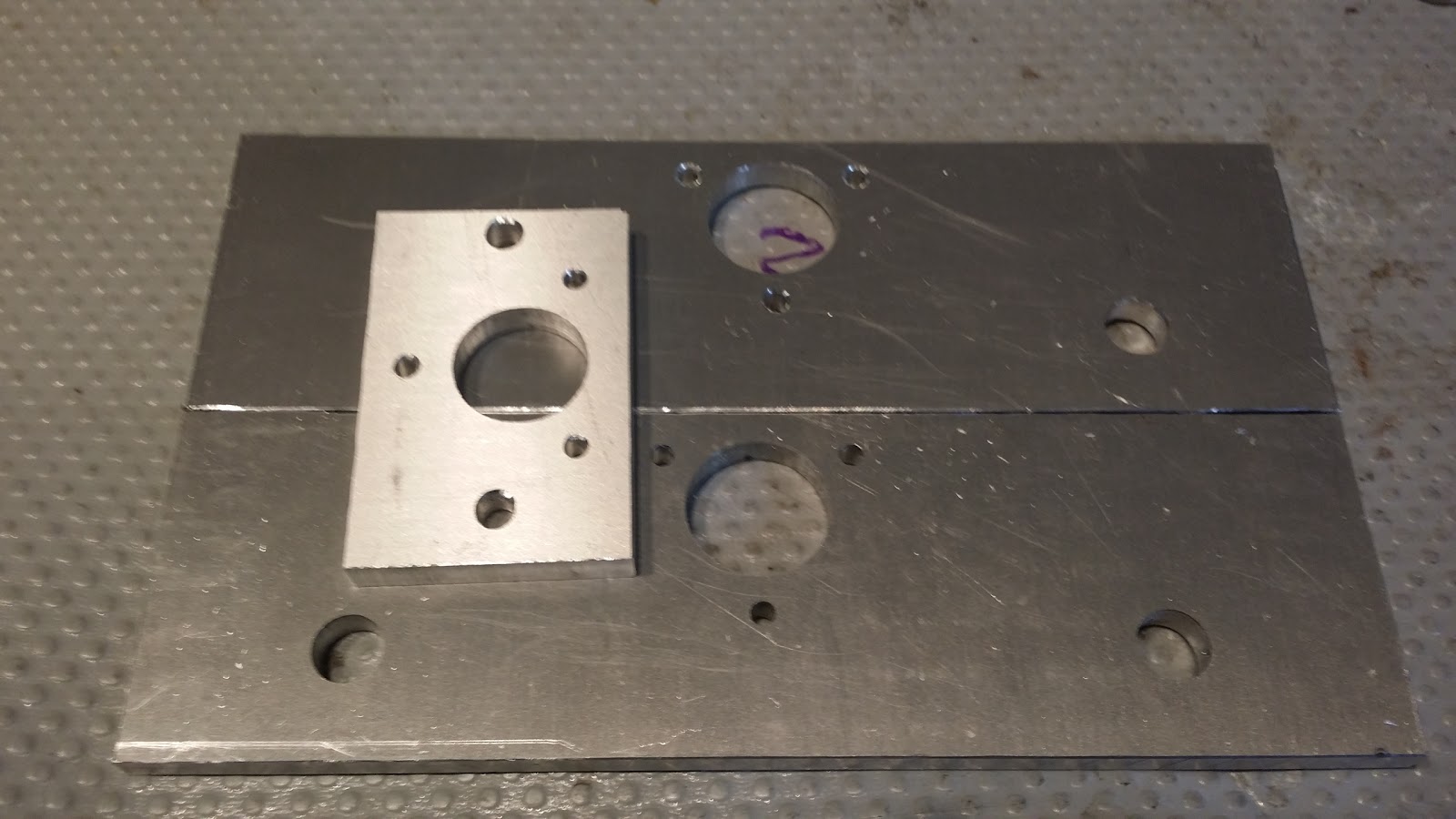

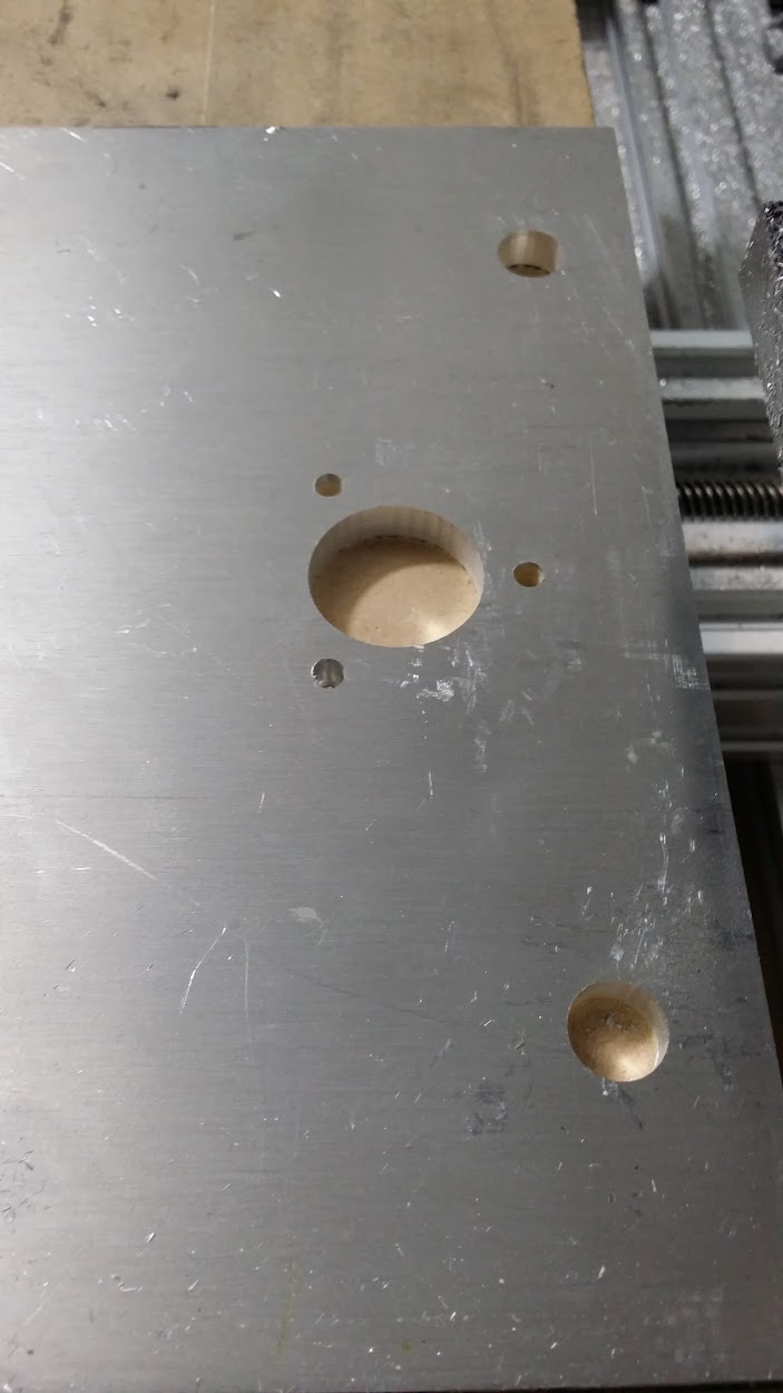
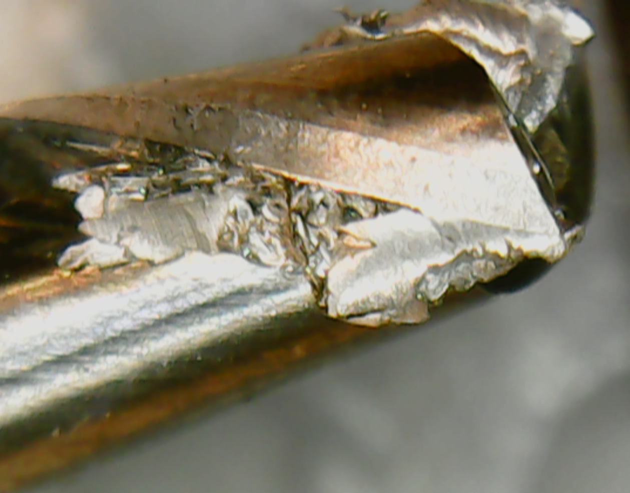
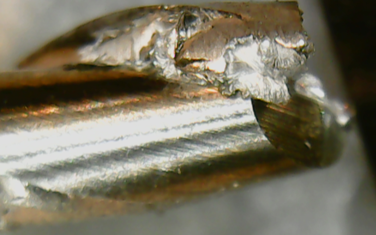
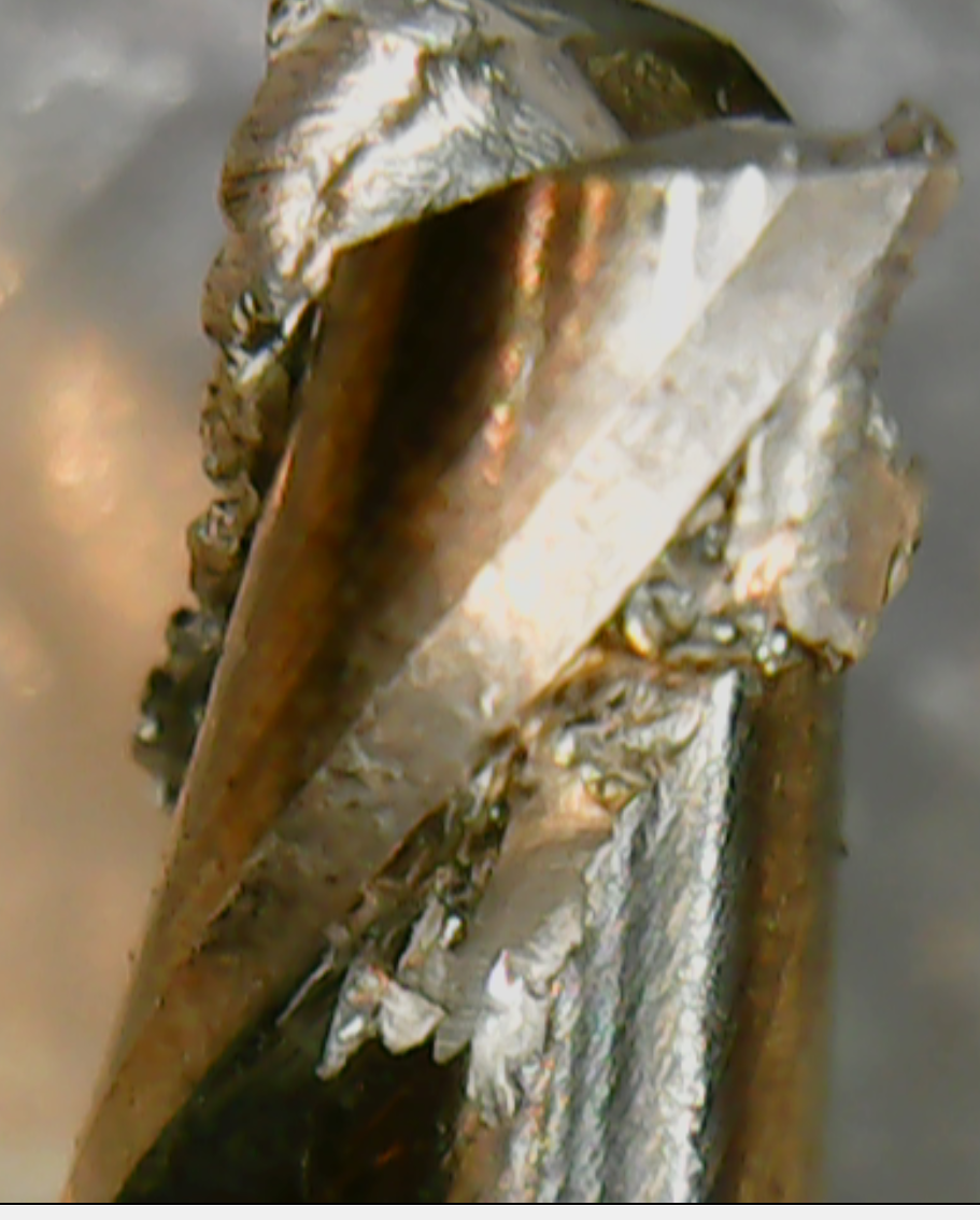
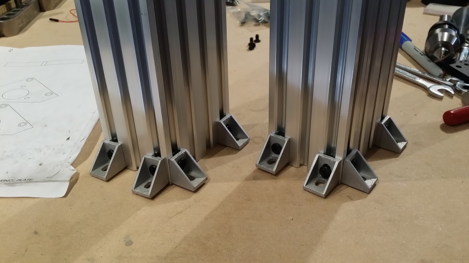
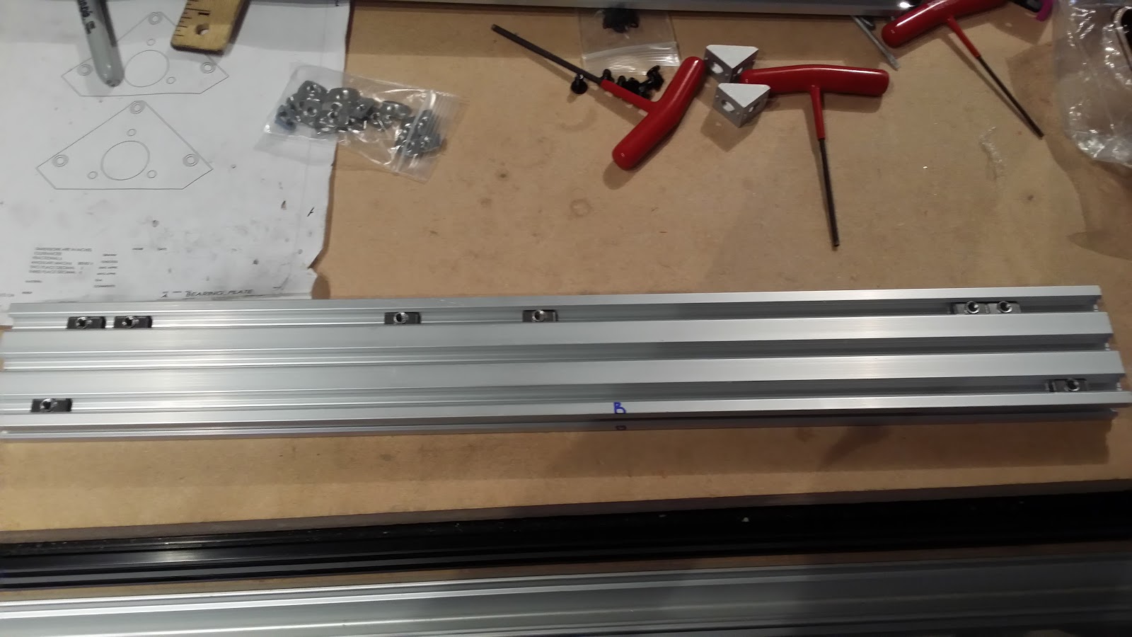
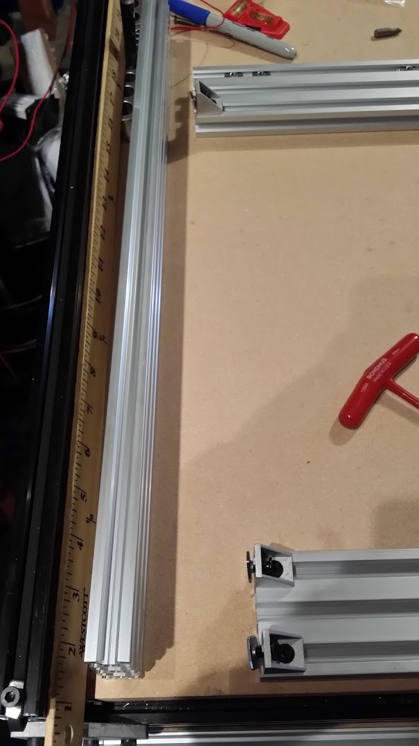
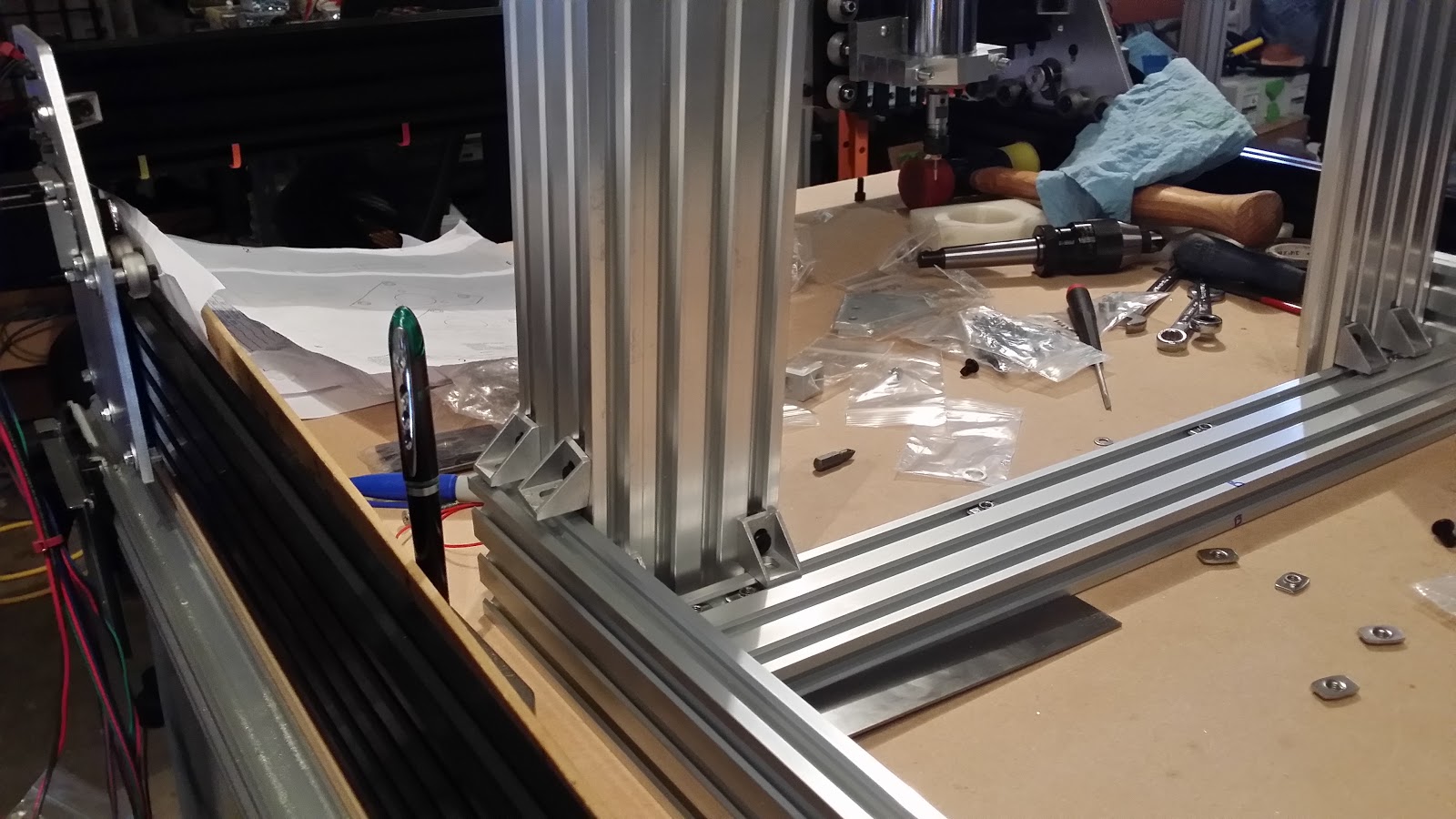
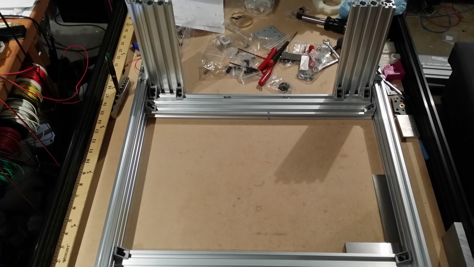
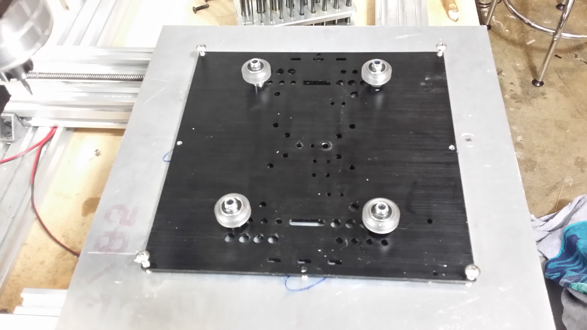
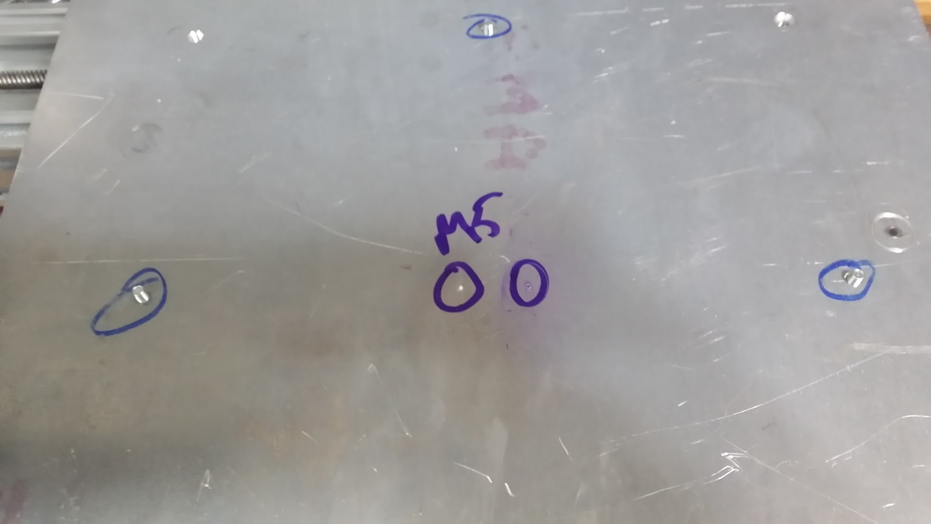
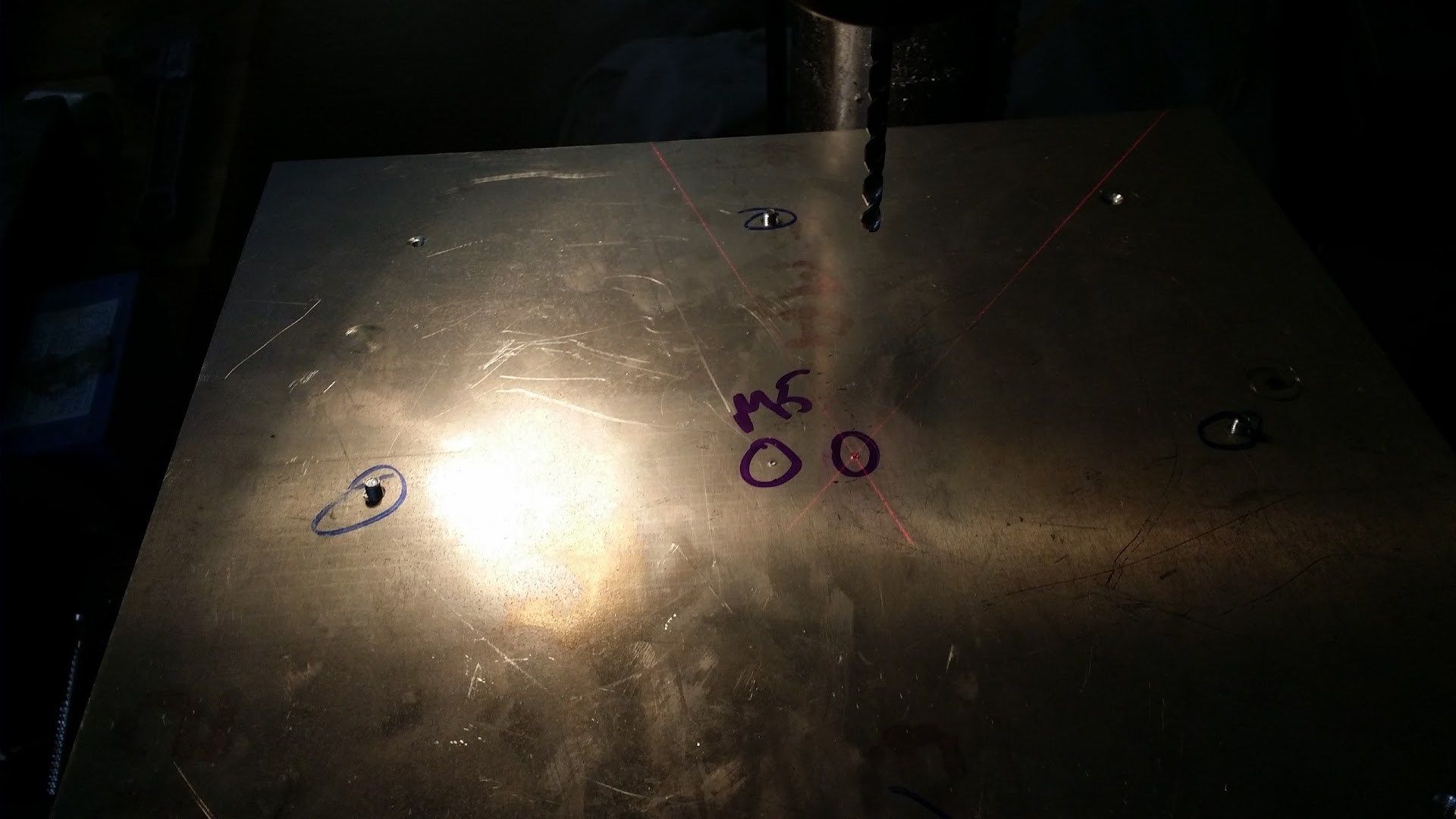
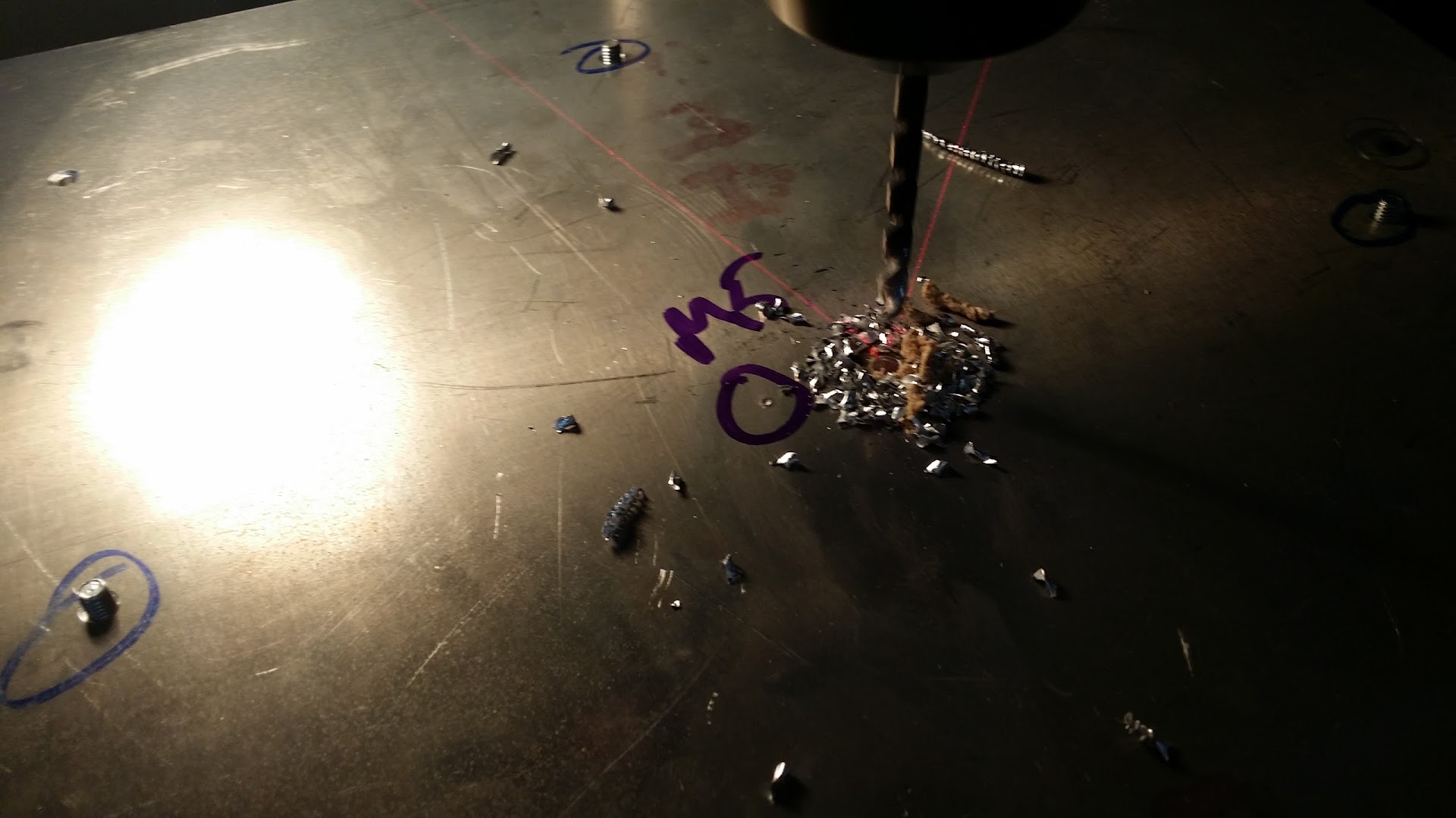
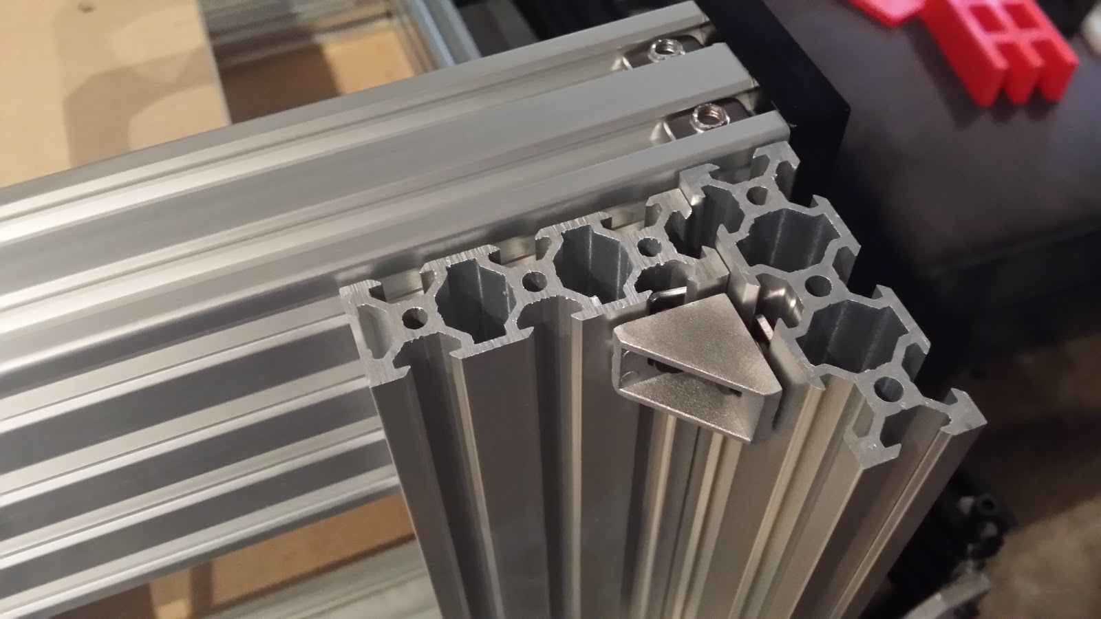
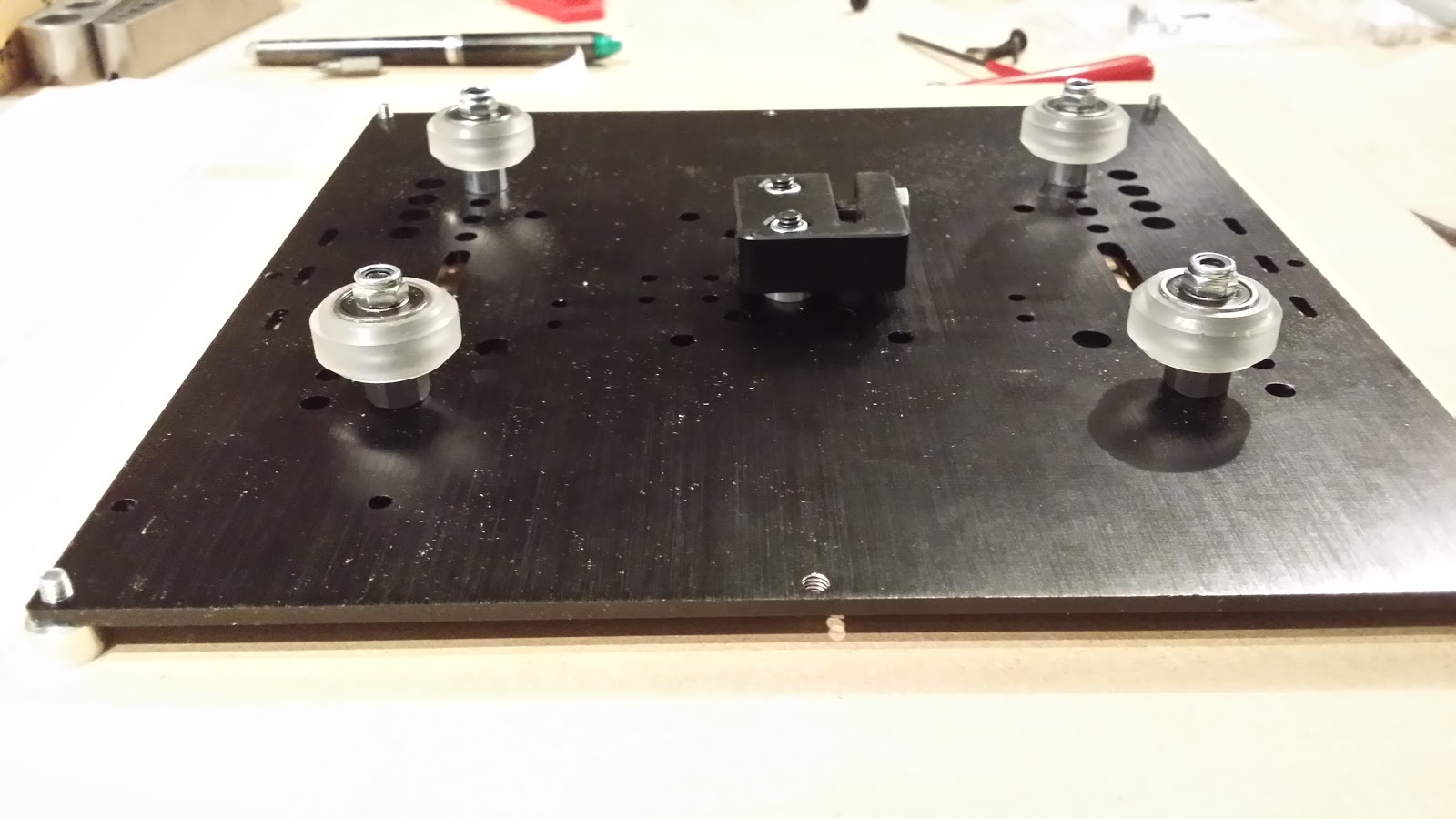
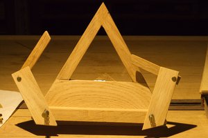
 the mismatches, all kinds of wrong
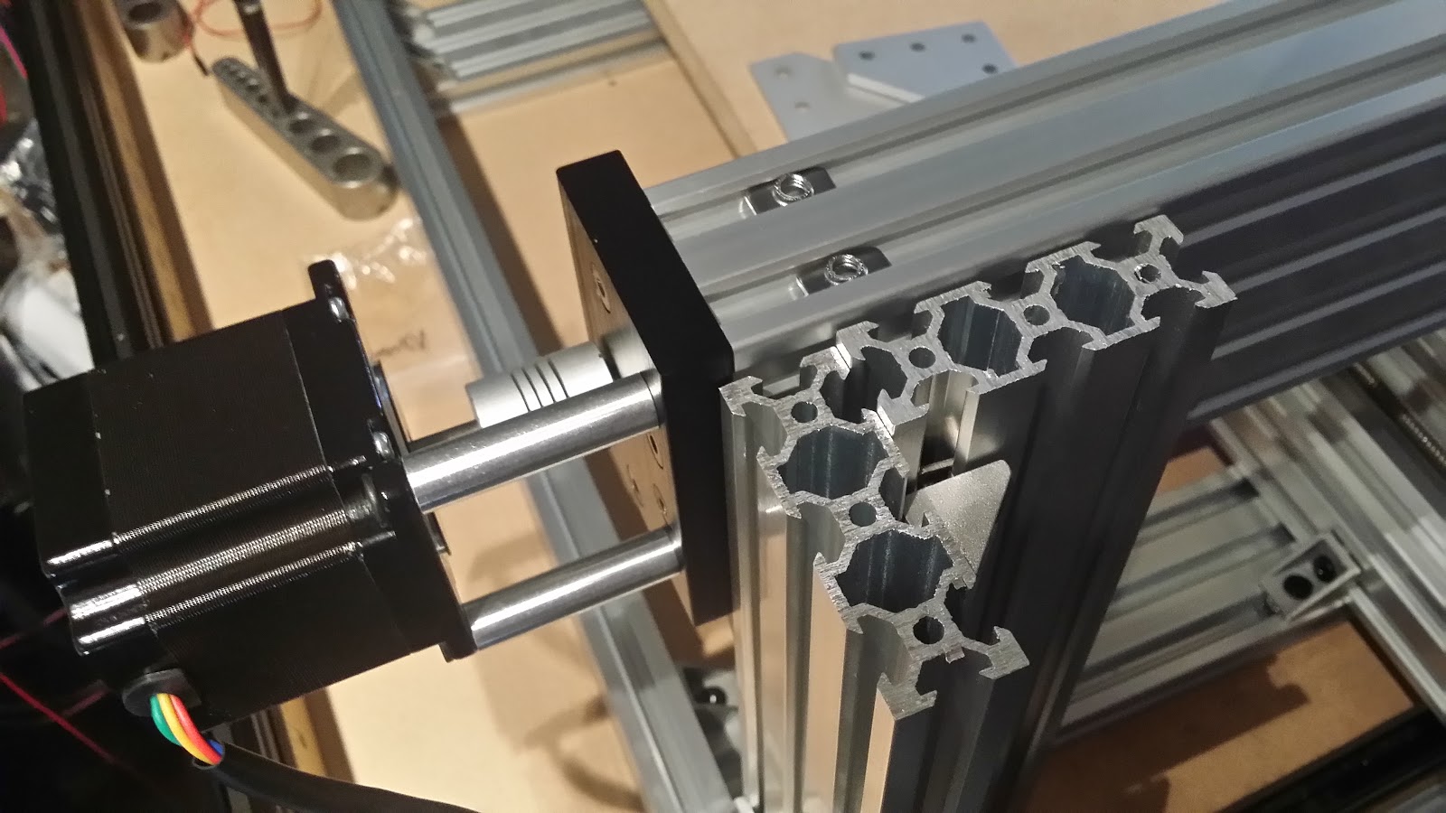


 [zit] Olivier Gade
 Magnus Selin