 ben biles
NEW DIGIBOARD , DSP XMOS STM32H7 , USBC, GB ETHERNET, TWIN SD CARDS, TC IO, TXCO RTC
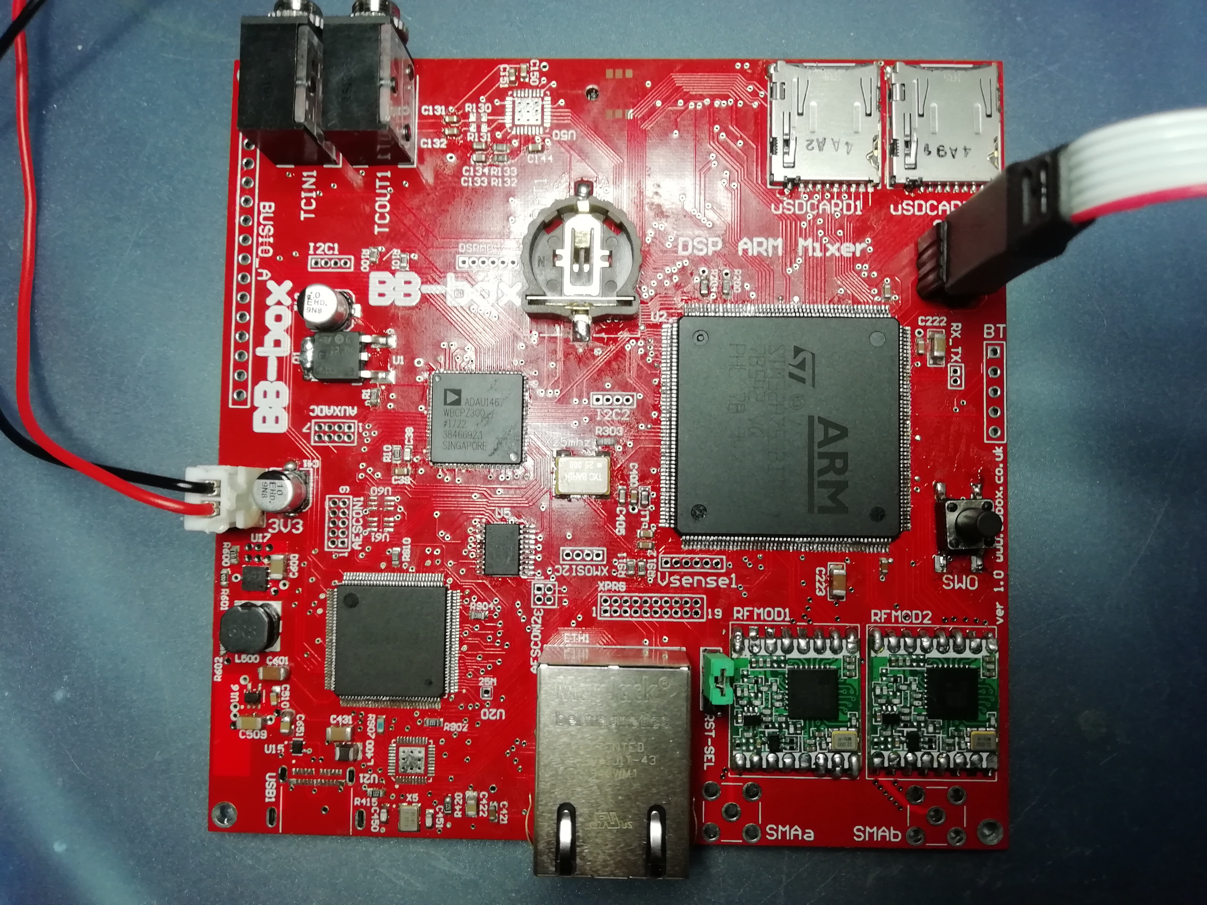
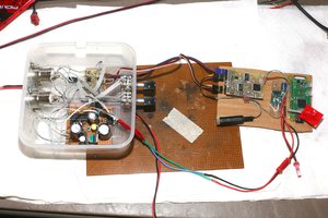
NEW DIGIBOARD
8 channels AES3
AVB gigabit ethernet audio
AES3 IO
USB C PC/MAC DAW connectivity
TXCO RTC for accurate time of day ( Timecode )
Individual Timecode IO , JamSync
Dual RF modules for digital audio link to camera ( or possible timecode to sync boxes )
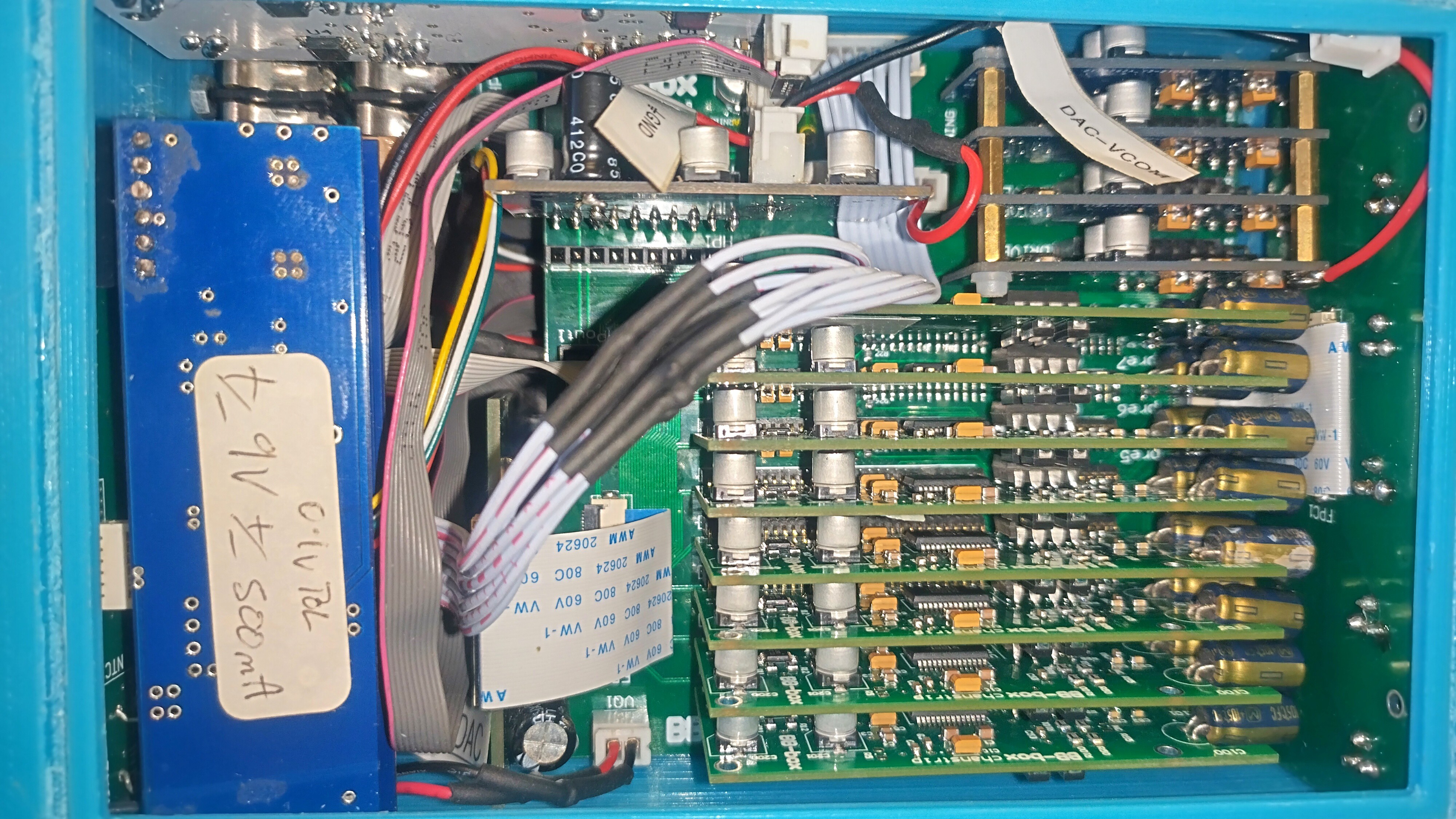
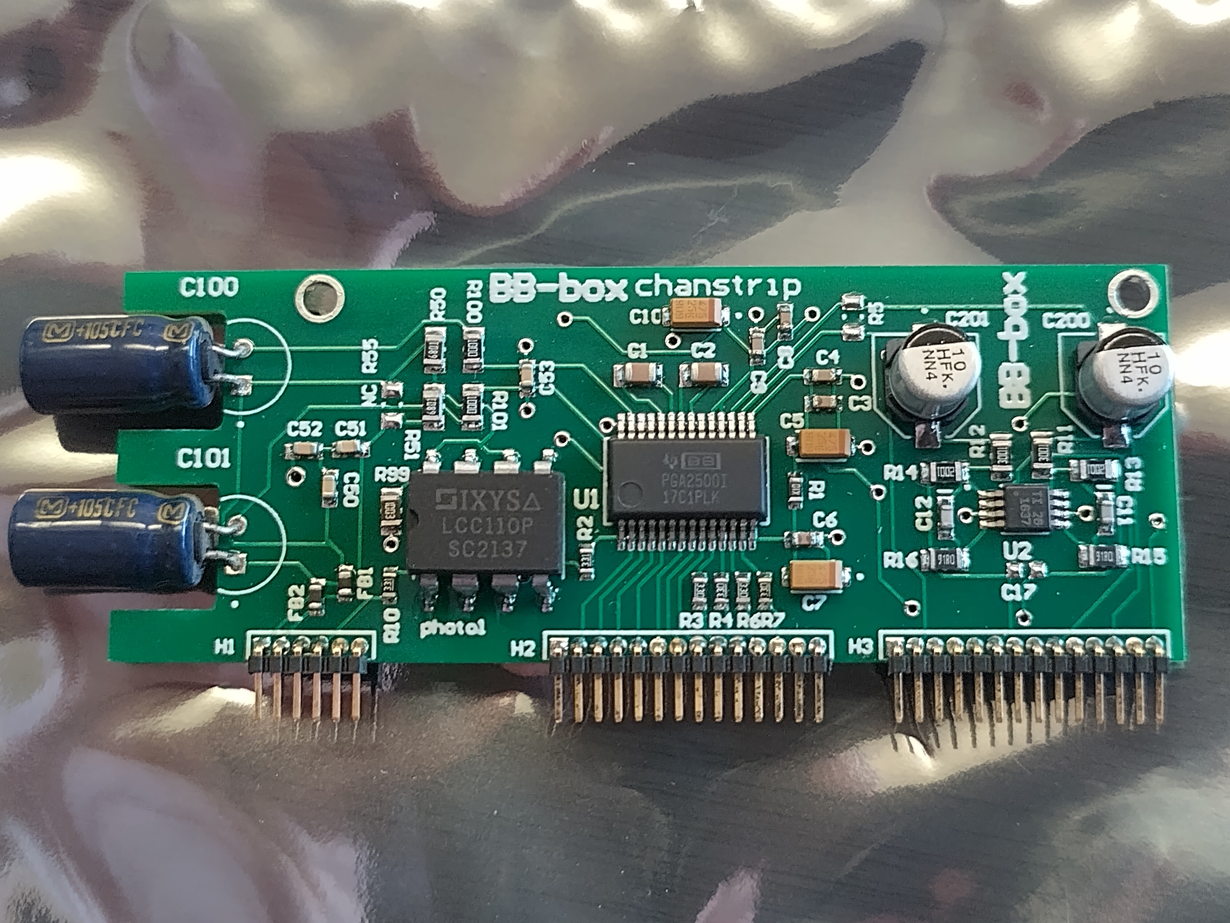
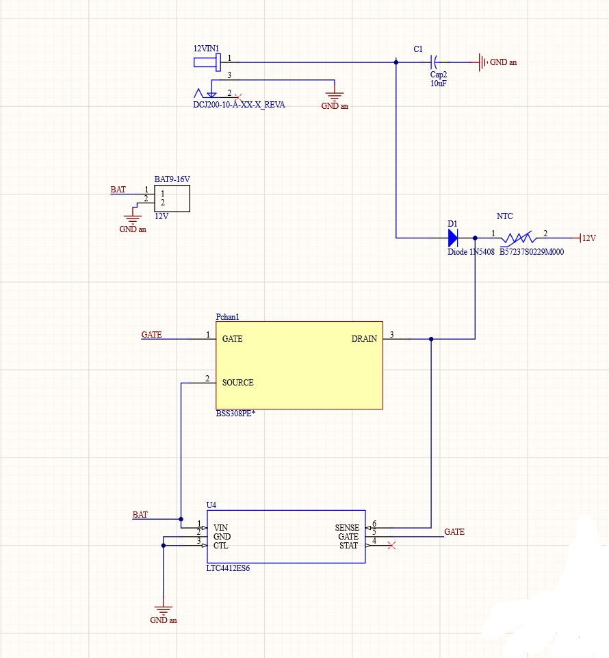
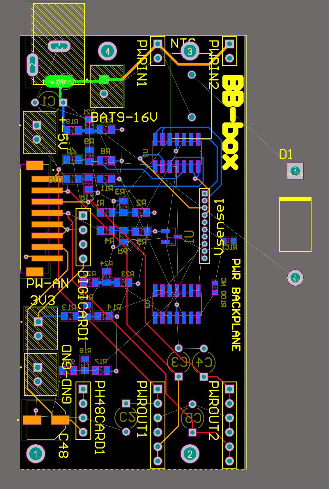
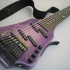
NEW ANALOGUE BOARD
isolated digi opto power switching for the preamps ( power saving )
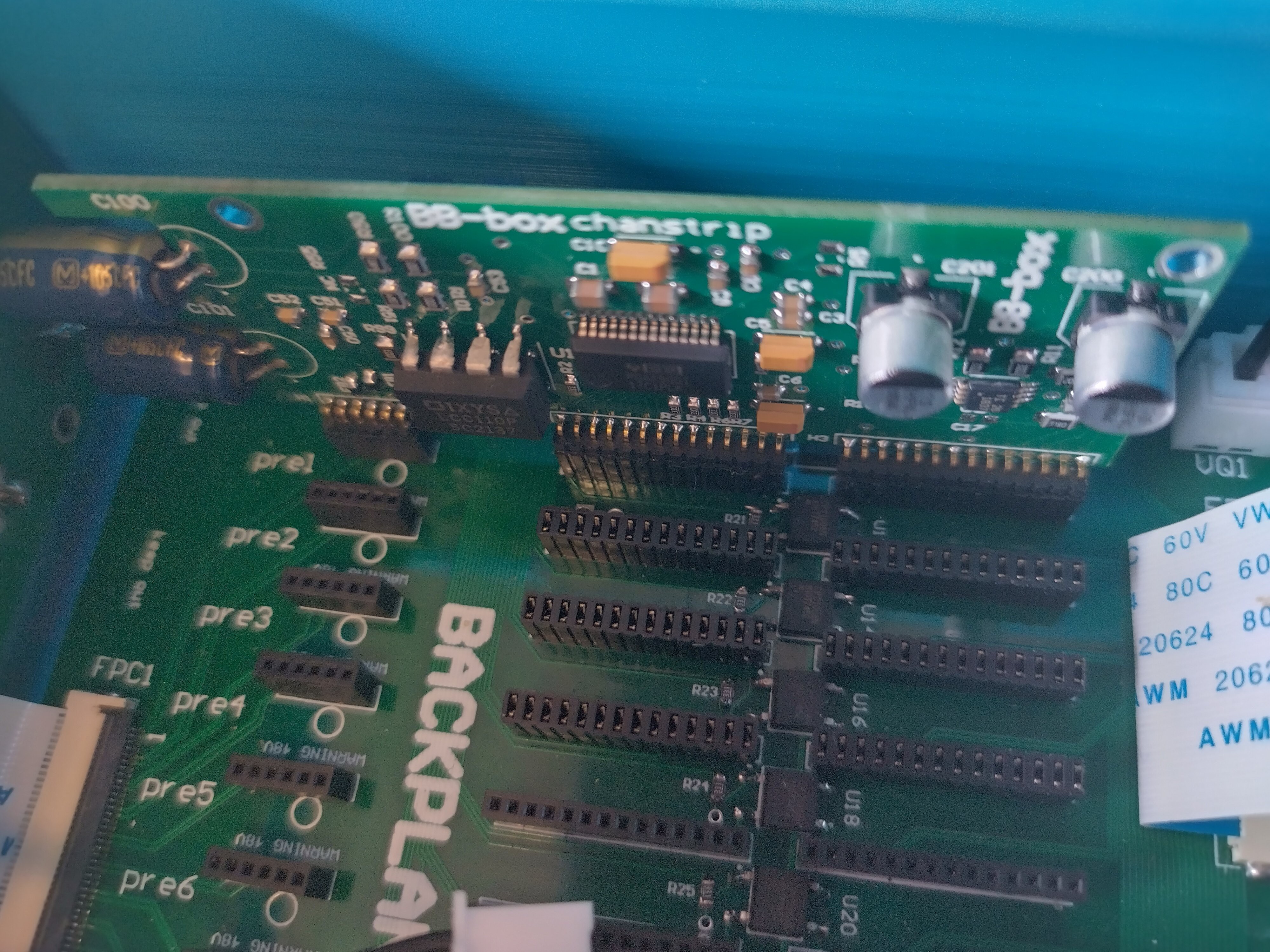
8 balanced 10 - 65db preamp cards on 1.27mm headers ( phantom power and 0db line level )
4 balanced line drivers cards
2 x very high quality headphone cards.
preamp front end limiters
Voltage monitoring
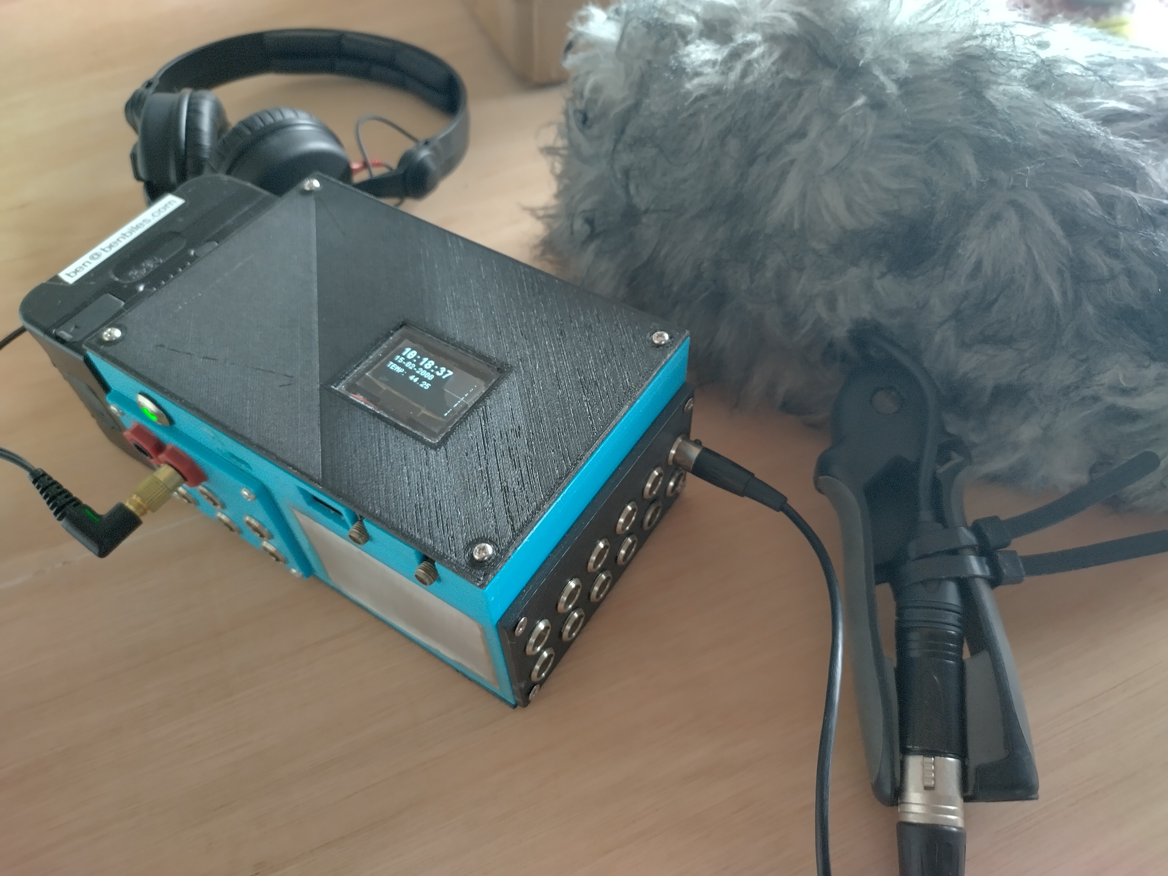
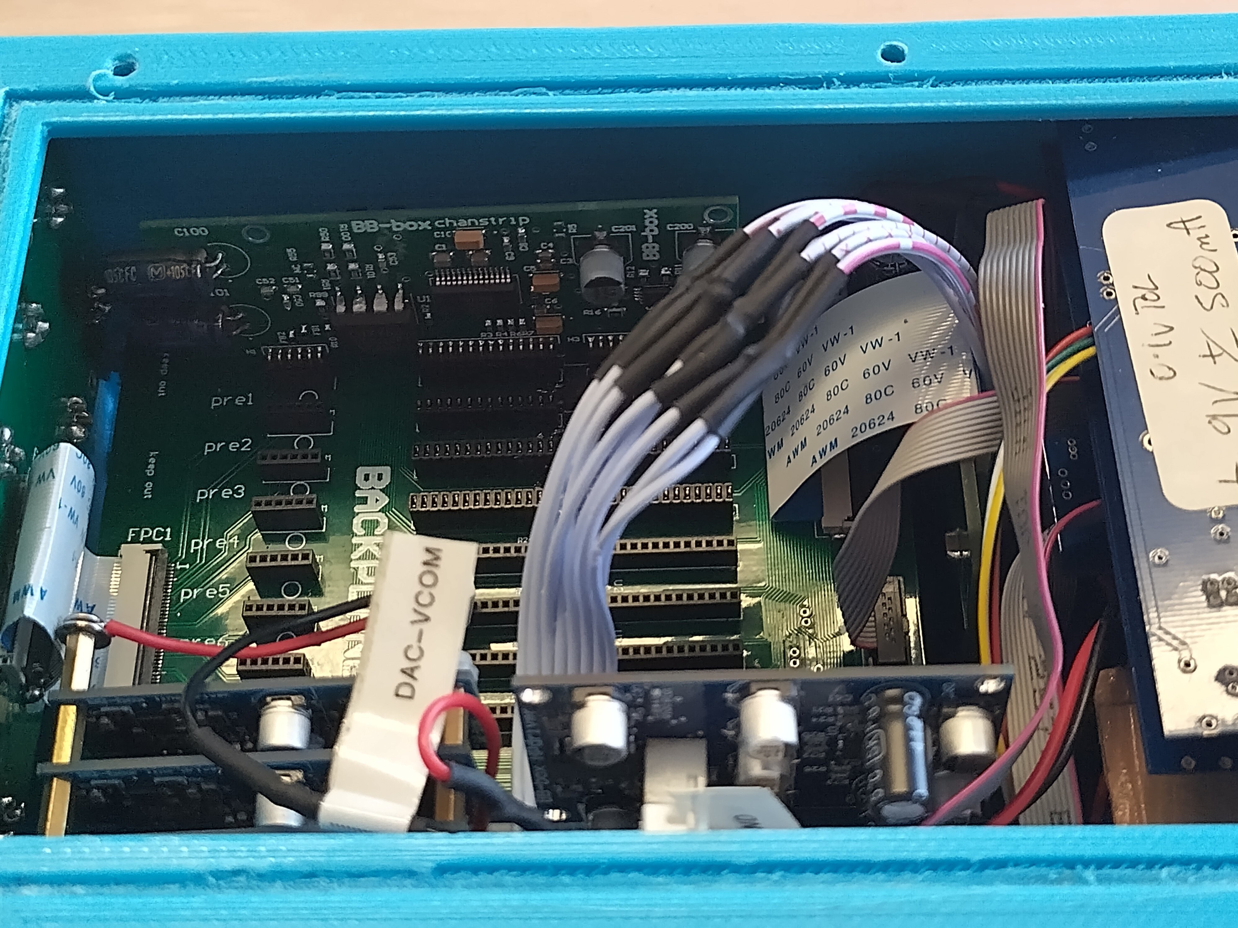
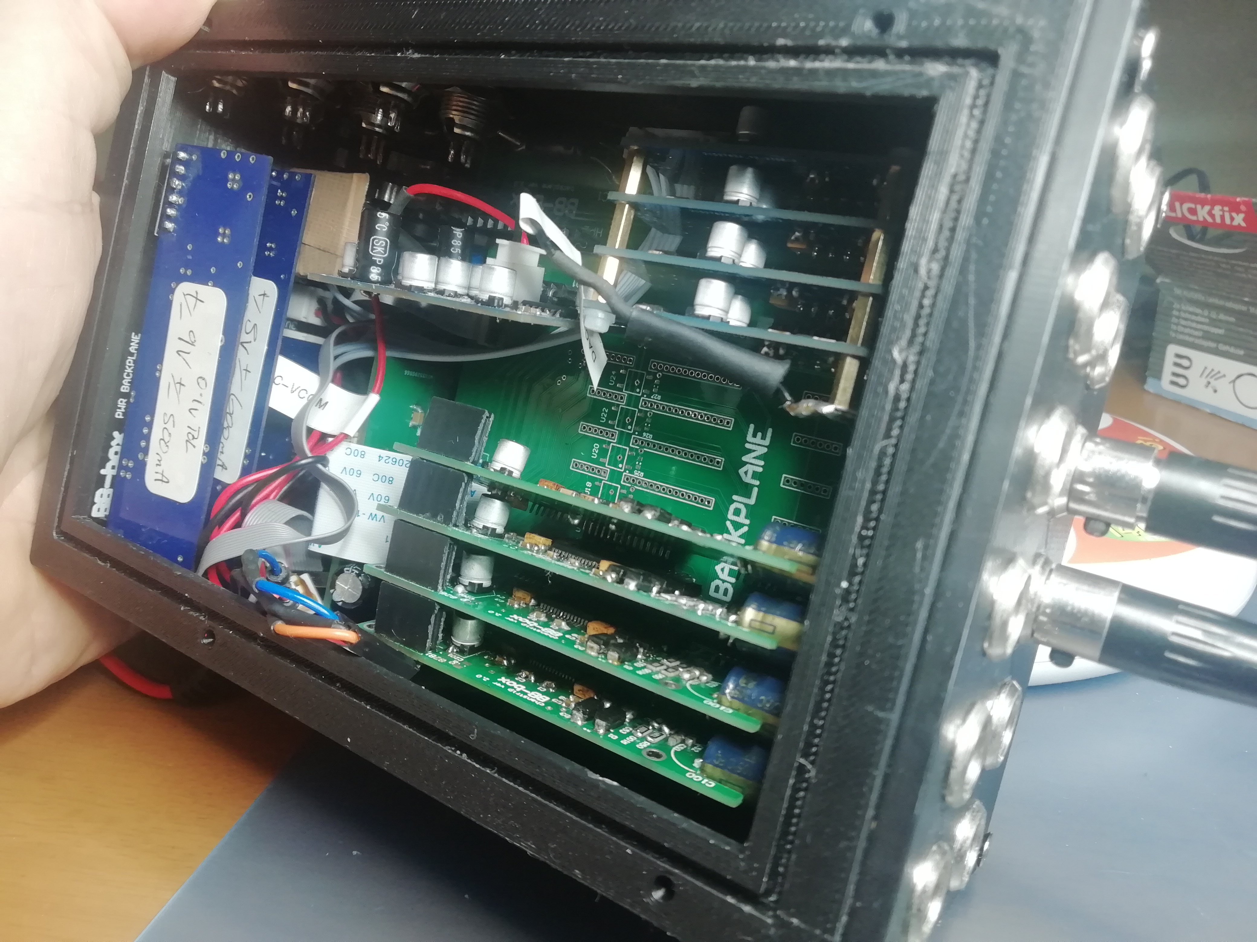
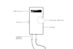
started printing 3d cases to try and get a design worth making out of aluminium or carbon fibre.
experimenting with changeable connector plates.
It's Alive !!! here's the 1st test recording for historic reasons :)
https://soundcloud.com/benbiles/bbbox-proto1-recording-48khz16bitwav
here's an old real-time audio meter input demo. was another mile stone!
The Bluetooth App does a lot more now also ! FX compressors LP HP filters etc.
_______________________________________________________________
The beginning , learning how to use SPI and I2C. I believe this ever worked :)


 Matt
Matt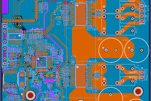
 lion mclionhead
Hi Ben, I've been coming back at your project from time to time for the past two years because it's quite close to something I've been working on. I'm designing what is for now a 10 channel (+2 line) portable, battery powered mixing desk for movie recording. It was analog at first and became a digital mixer. I kept the analog controlled mic pre (although I'm thinking about a design with a VCA controlled mic pre with an integrated limiter and digital gain control through VC preamp gain), filters and limiters. The adcs comes right after the limiters.
I've been thinking on rather going with the same ADAU1467 and STM32H7 design that you've been using for the digital part or rather sticking to only using an STM32H7 and doing everything from there. Do you know if the STM32 itself could be usable as a DSP for that project ?
To give you an idea, I would need to input 16 channels into the DSP and have 18 outs. And an idea would be in the futur to expand it to 24 channels in and 26 outs to add 8 AES EBU I/Os.
It's worth pointing that the 8 SRC inputs on the ADAU would be perfect for AES inputs.
I've been trying to find any infos on if it's possible to go in and out the STM32 through TDM8 or 16. Given that I didn't find any informations on it, do you know if it's doable ?
What seems to be one of the STM32 biggest limitation is that it actually lacks enought inputs to design audio mixers.
For the background story, that project is my master thesis work but has started going way further than that.
I'm actually a sound engineer rather than an electronic student, and designing that kind of stuff is something that I've been learning on my own.
Thanks for you help ! And for sharing your work here, it has been very interesting to look at.