Insight Machines Lab
This was supposed to be a weekend project but it somehow got stretched a bit... Into almost eight weekends. The main functionality of an alarm clock is trivial - measure time and play an alarm sound when the alarm time is reached. And it wasn't the main functionality that stretched the project's duration so much. It was all the small things that make the device actually usable - the enclosure, the knobs, the display, recharging etc.
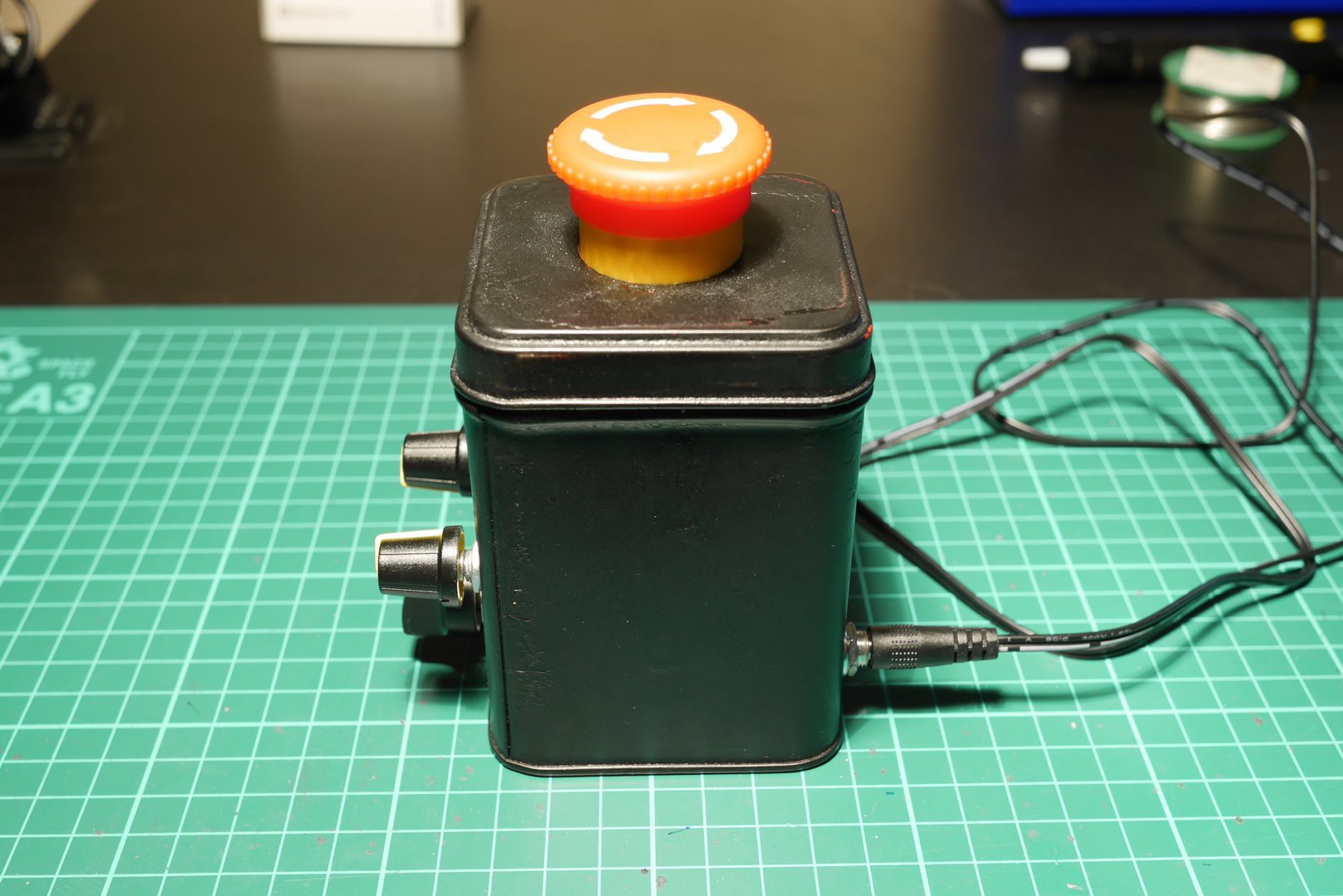
We started off with a red, metal, tea can that we painted black (not without some difficulties):
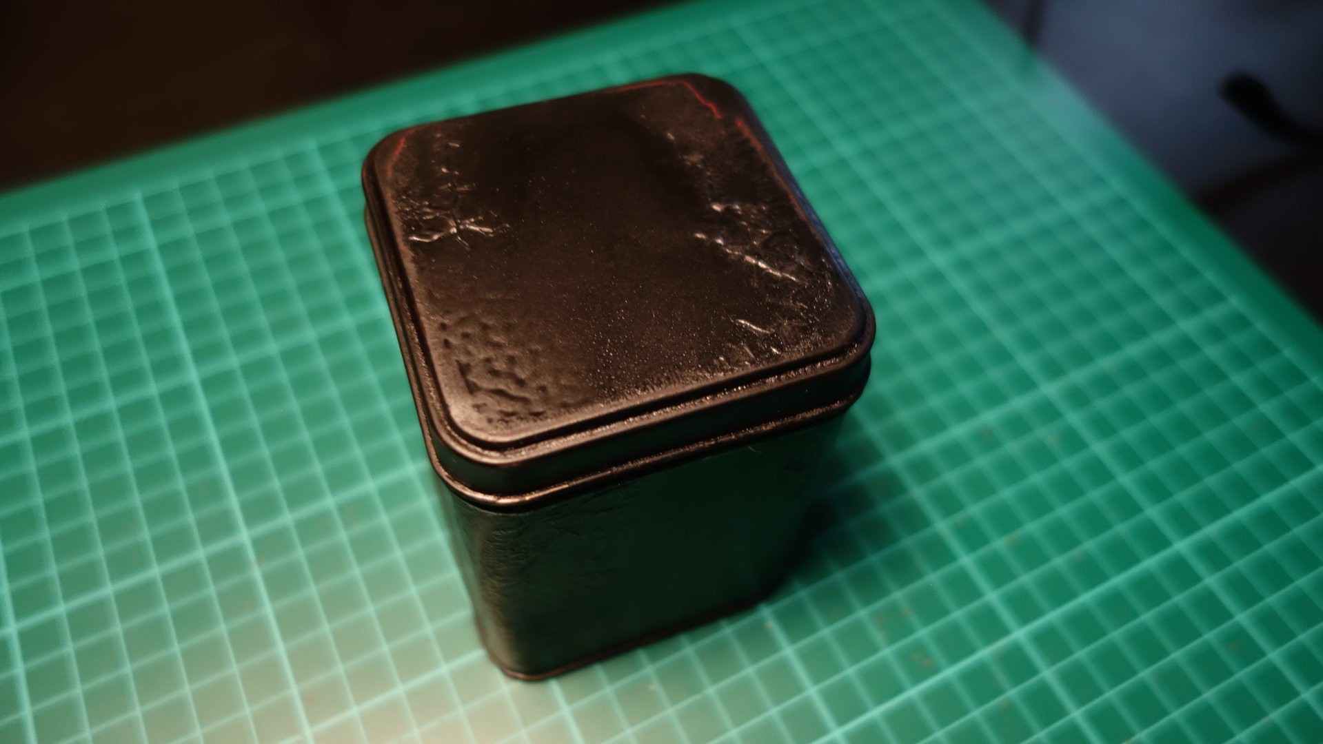 The can seemed perfect as it had the right size and could be easily opened. It was also quite stiff to provide a sturdy enclosure for the device.
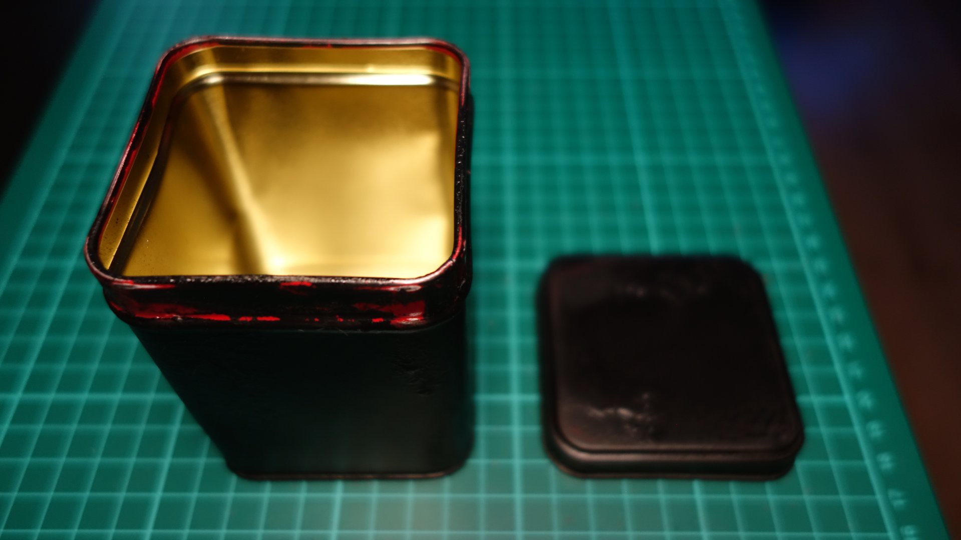
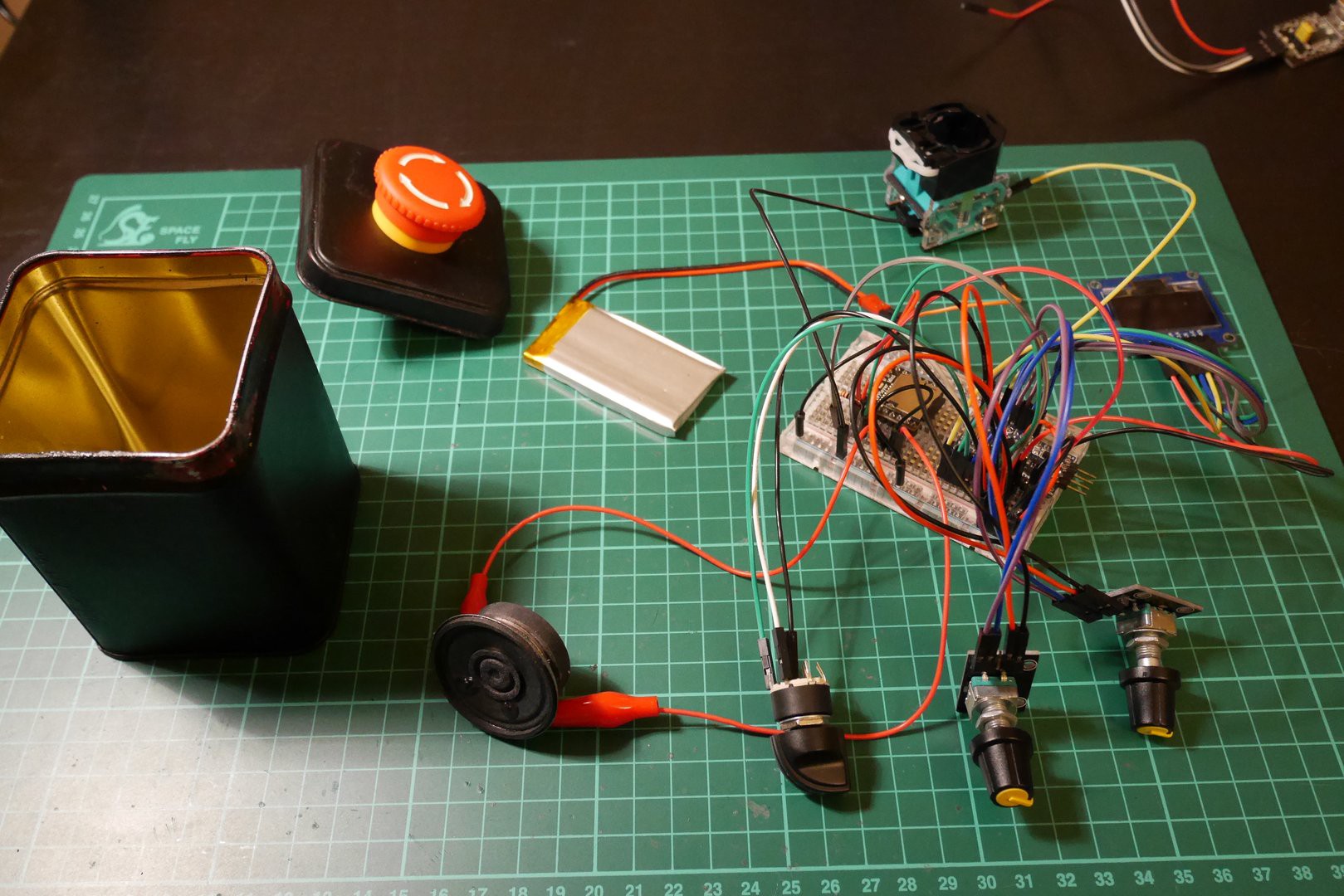
Next, we connected all components together on a breadboard:
 The connections diagram below, depicts how all the components were connected to each other:
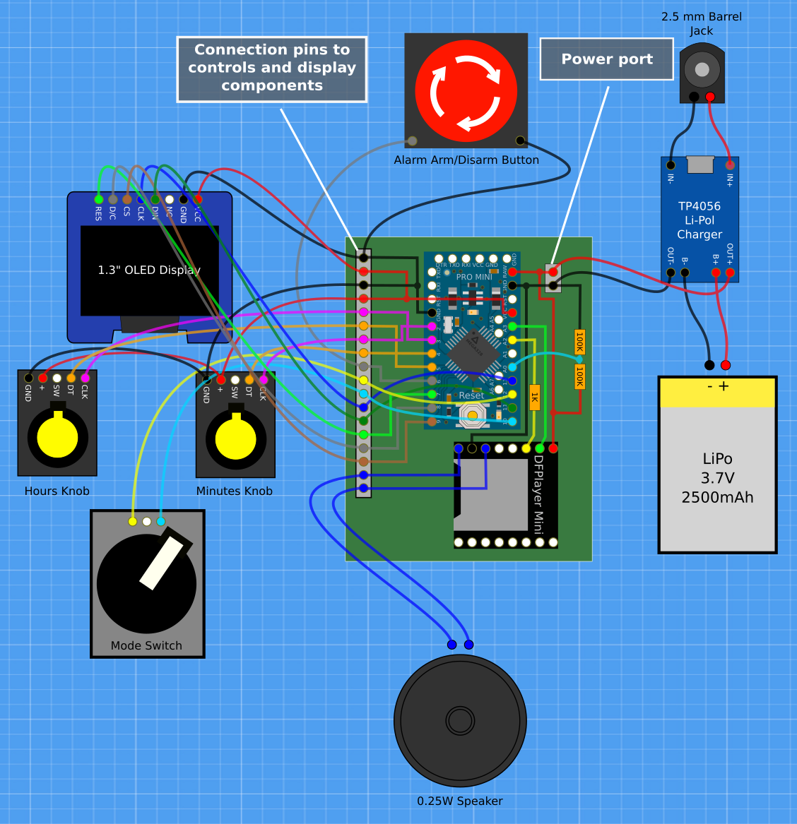
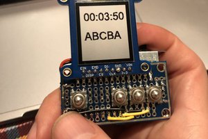
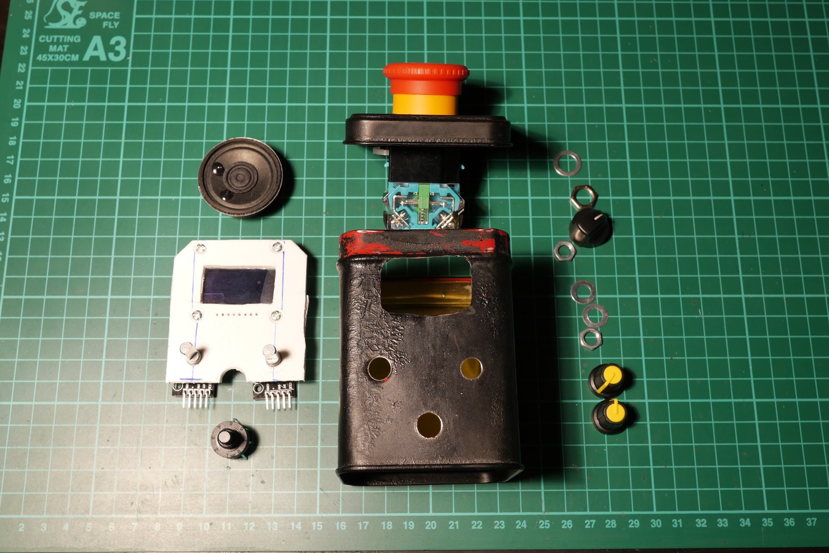
We decided to use two knobs with encoders - one for setting hours and the other for minutes - and a three-state rotary switch. The switch would allow the user to set the mode of operation to either "regular", "set time" or "set alarm". Then there was the big push button at the top of the can that would arm the alarm and disarm it. We wanted to try out an OLED display so we decided to use a 1.3", blue SH1106 OLED display to show the time and device state icons (e.g battery status). The alarm sound was supposed to fit the industrial look of the device so we found an MP3 with submarine diving alarm on SoundBible (the sound was recorded/synthesized by Daniel Simon). To play this MP3 we employed a DFPlayer Mini module connected to a 0.25W speaker (a bit too weak actually, but small enough to fit into the can with all the other components). As a micro-controller, we chose to go with the Arduino Pro Mini (3.3V, 8MHz). Finally, we wanted this gadget to run off a battery so we included a 2500mAh LiPo battery, a charging module and a barrel socket for easy recharging.
The biggest challenge was to get all those "user interface" components to fit nicely together. We wanted the knobs to be mounted on the front side of the device, just under the display and above the mode switch. Initially, we considered mounting all those components separately onto the front side of the can but it quickly became apparent that this approach wouldn't work too well as the knobs required a thicker surface to be mounted on and the display required four screws and some space between its board and the surface it was to be mounted on. Hence, we decided to cut a piece of PCV - more or less the size of the whole front side of the device - and mount the display and the knobs to this PCV. We would then mount the PCV inside the device using the openings for knobs and the nuts that came with them. The display would be mounted only to the PCV which eliminated the need for drilling more holes in the tea can and we ended up with a clean, no-bolt look. The PCV also turned out to be a great template for making openings in the can:
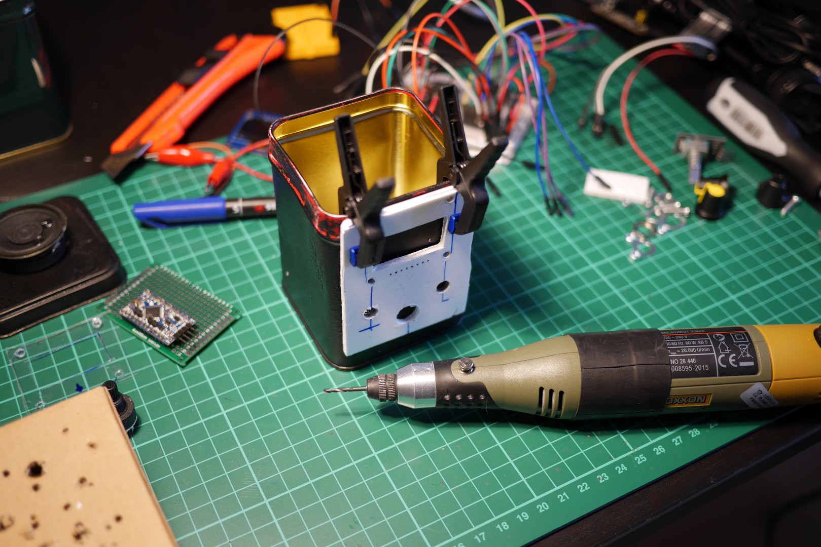
After drilling the holes for the knobs, we were able to mount the PCV to the front of the can and use it to drill/cut the remaining openings exactly where we needed them:
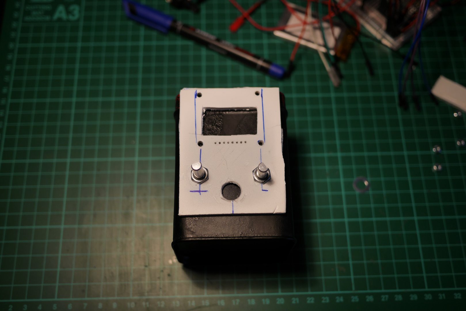
We ended up with with four openings in the can's front and a PCV with display mounted onto it (shown below with other components laying around):
 The PCV fitted nicely inside the can along with the speaker that we mounted on the bottom with a piece of double sided bonding tape:
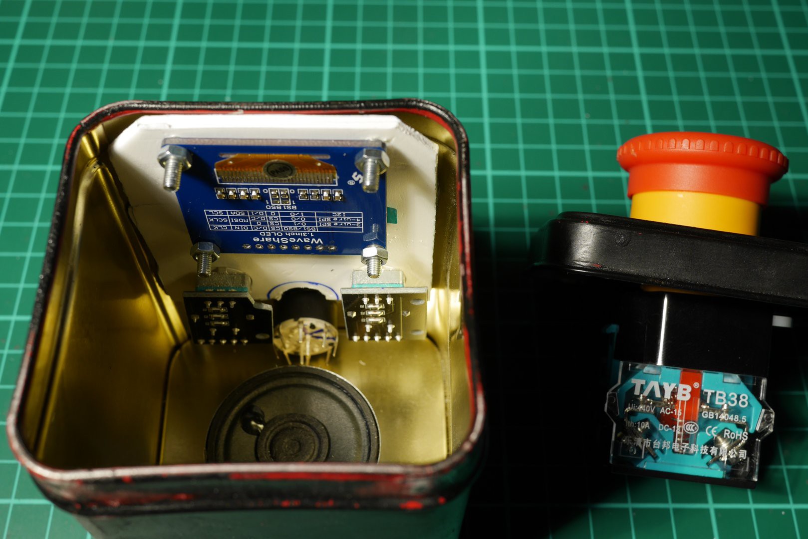
The next phase was to assemble the board with Arduino Pro Mini and the DFPlayer module:
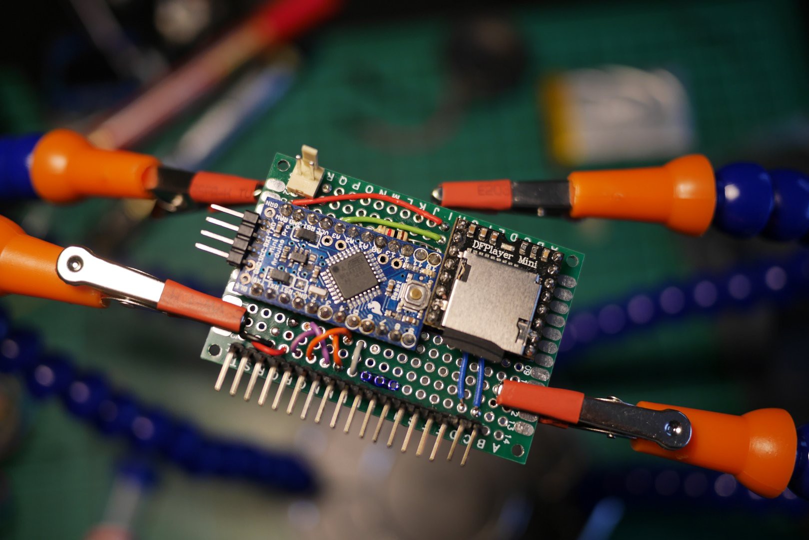
The board has 18 pins on its side that connect the Arduino and the DFPlayer to all external components. There's also a special two-pin socket for connecting the battery. The four pins on the Arduino Pro Mini are used only for programming and are usually left disconnected.
There are quite a lot of wires inside that can:
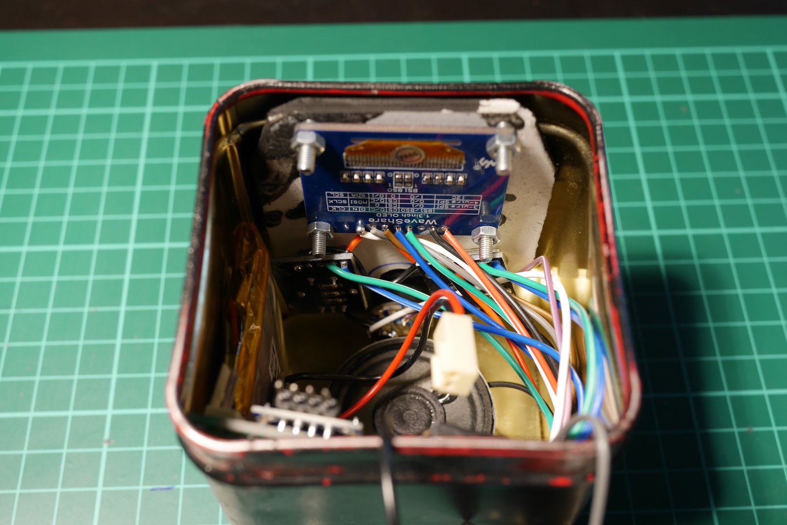
The battery is mounted on the side of the can. The charging module is mounted...
Read more »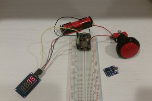
 Patrick Graham
 Joshua Snyder
 mircemk