 AVR
AVRThis week I glued the manifolds for pumping and draining water through the NFT system.
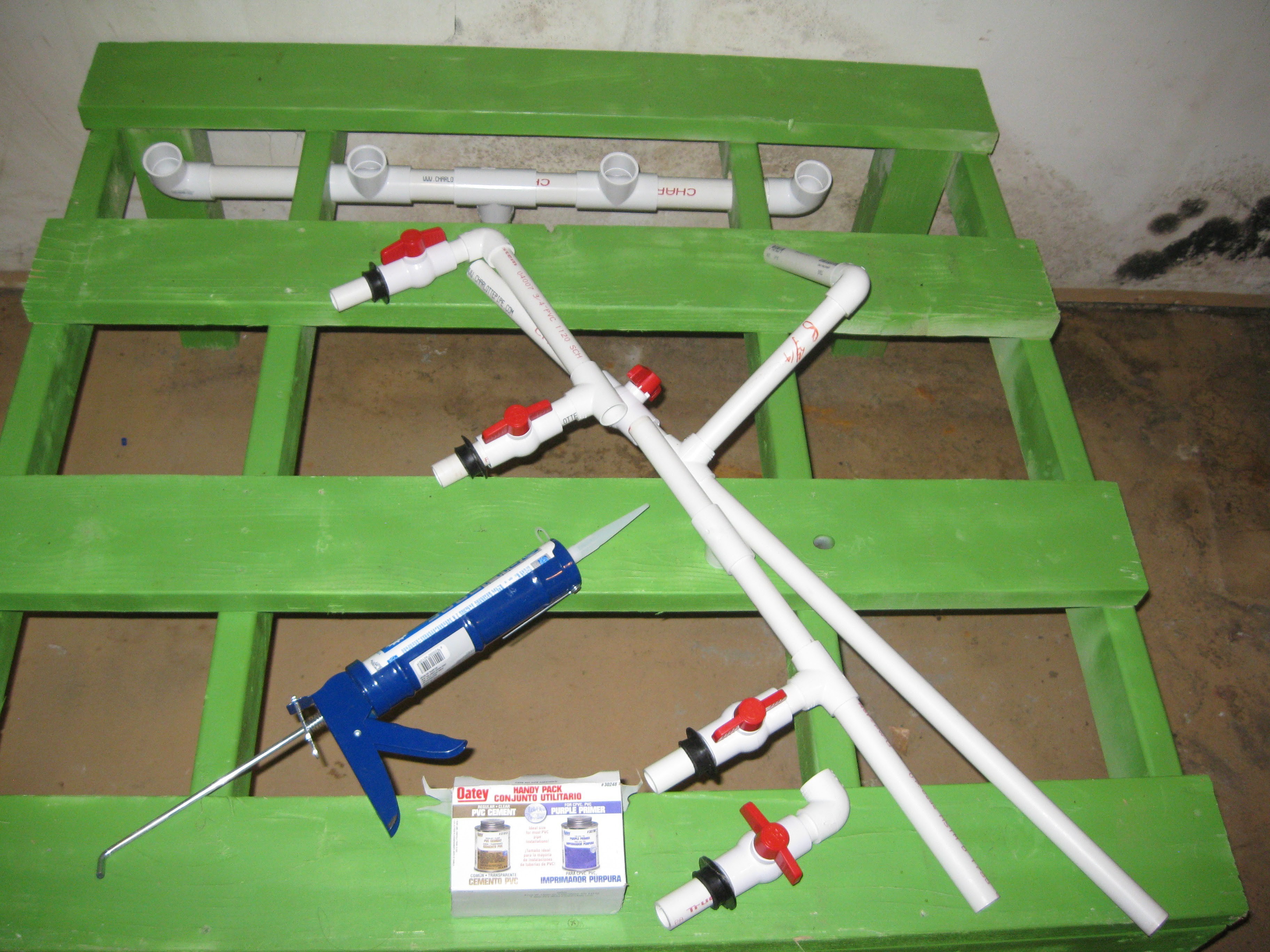
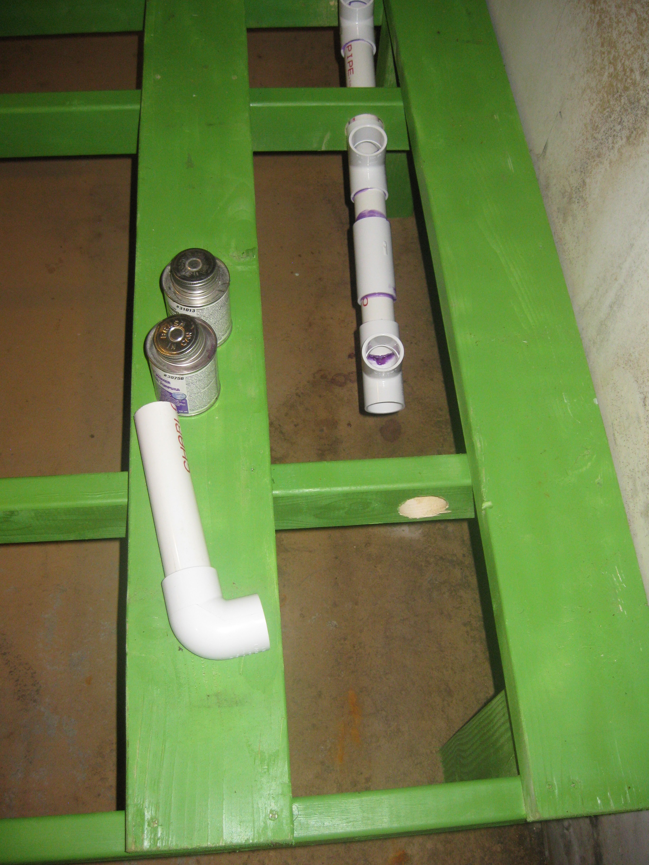
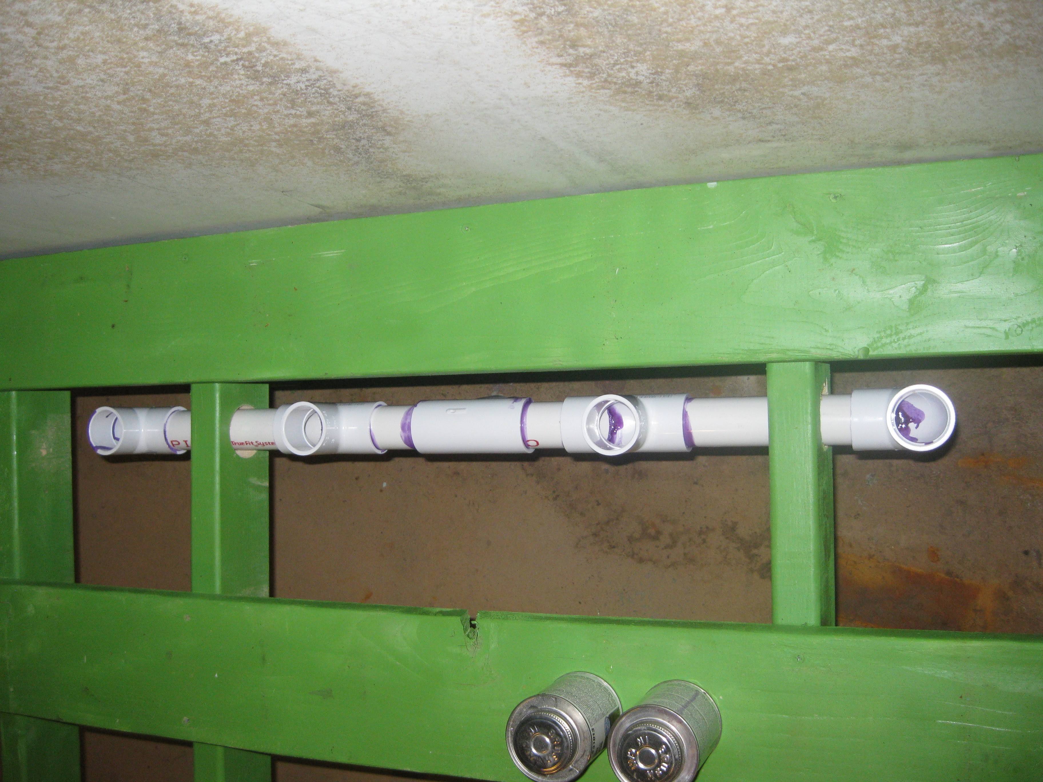
Dry press fit the drain manifold in place, Input manifold in pieces.
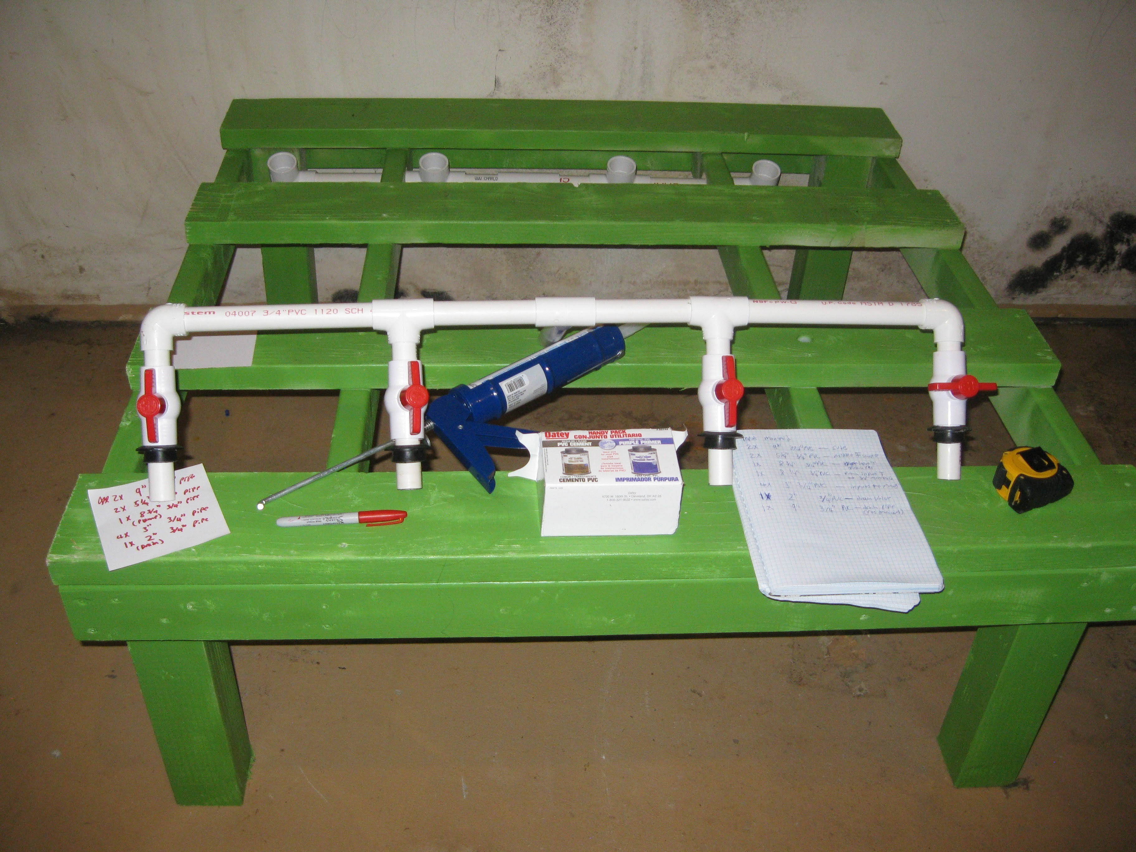
Input manifold dry fit together.
Drain manifold gluing process, the manifold is assembled within the frame, it gets permanently installed this way but it adds rigidity to the system and serves to lock the fence post grow rows in place.

One side assembled
Midway assembling second side of drain manifold.

Another view
Second half of manifold completely assembled.
Another view of the completed manifold

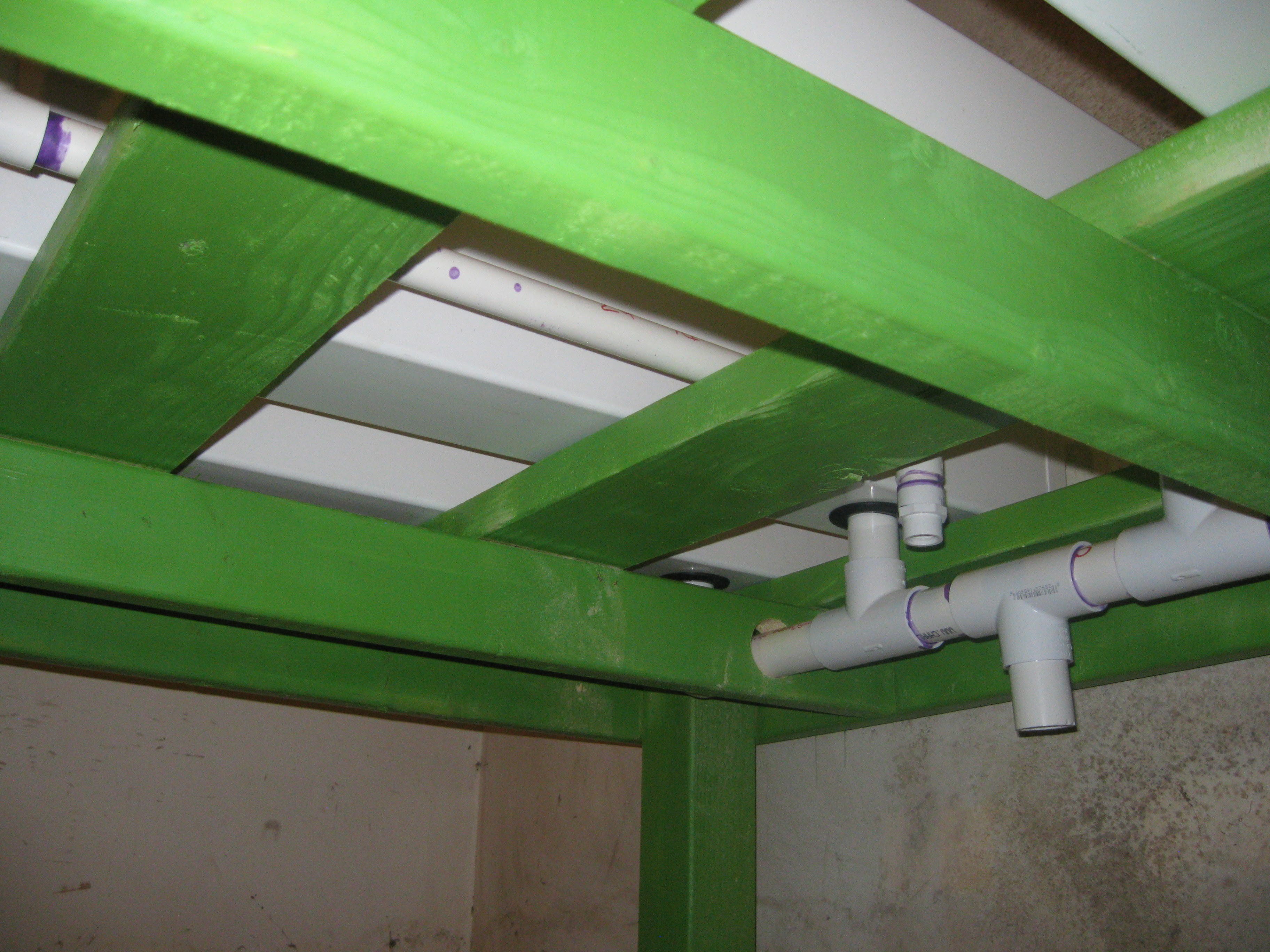
View from beneath, all four drains from the fence post rows converge to this output, it protrudes about an inch into the reservoir.

Another view from below
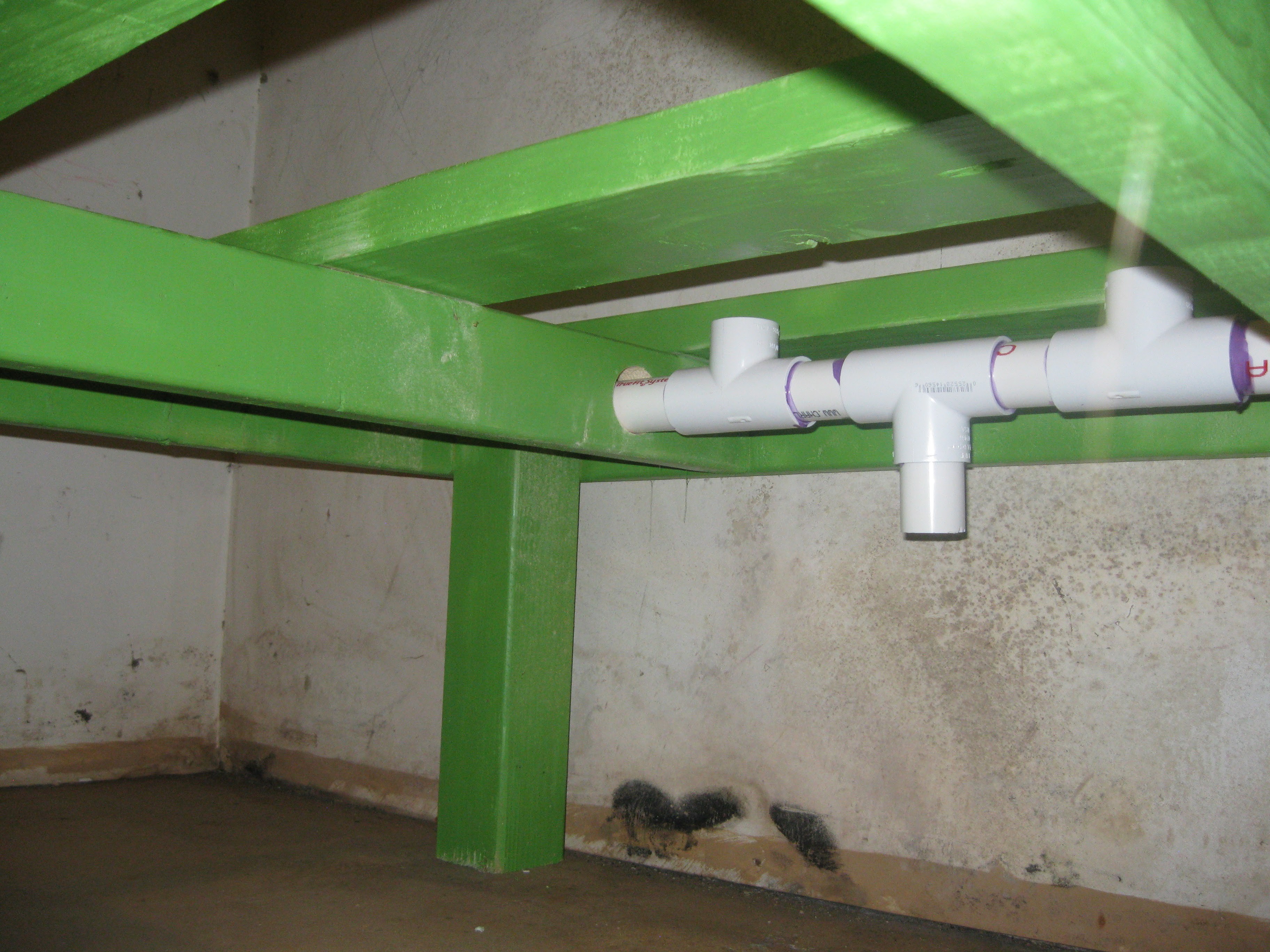
A view from the side below.

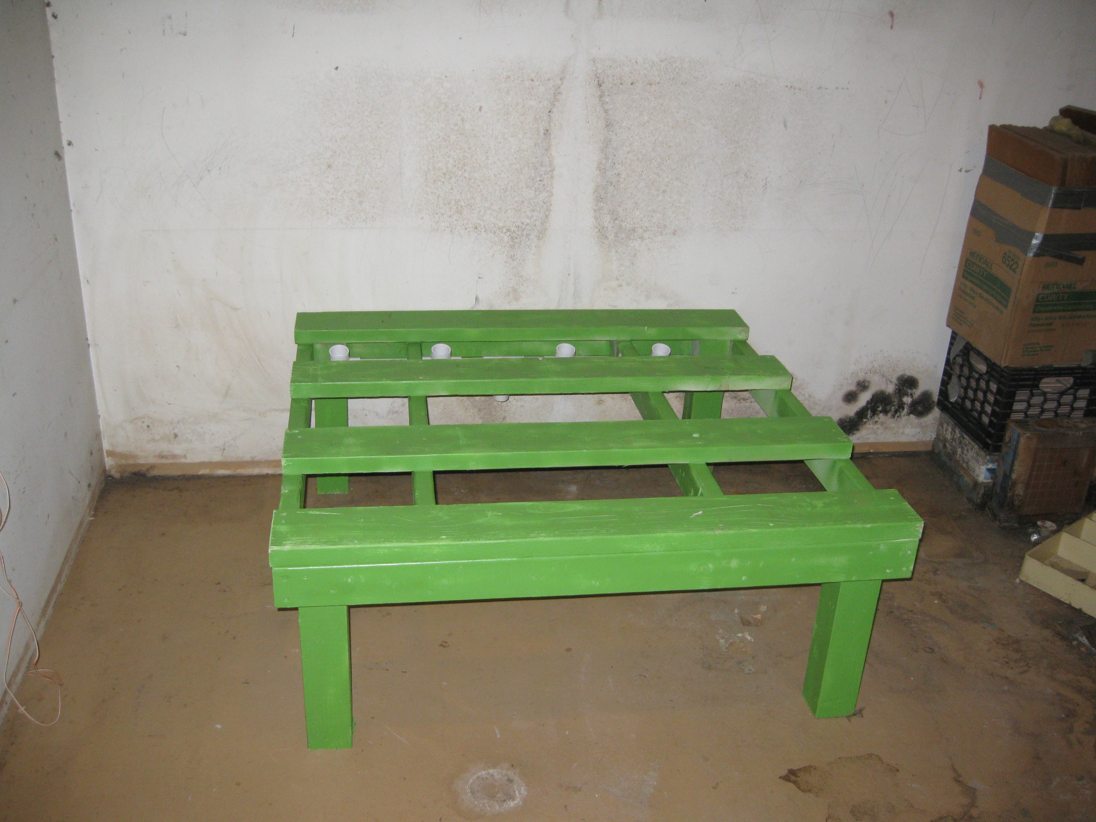
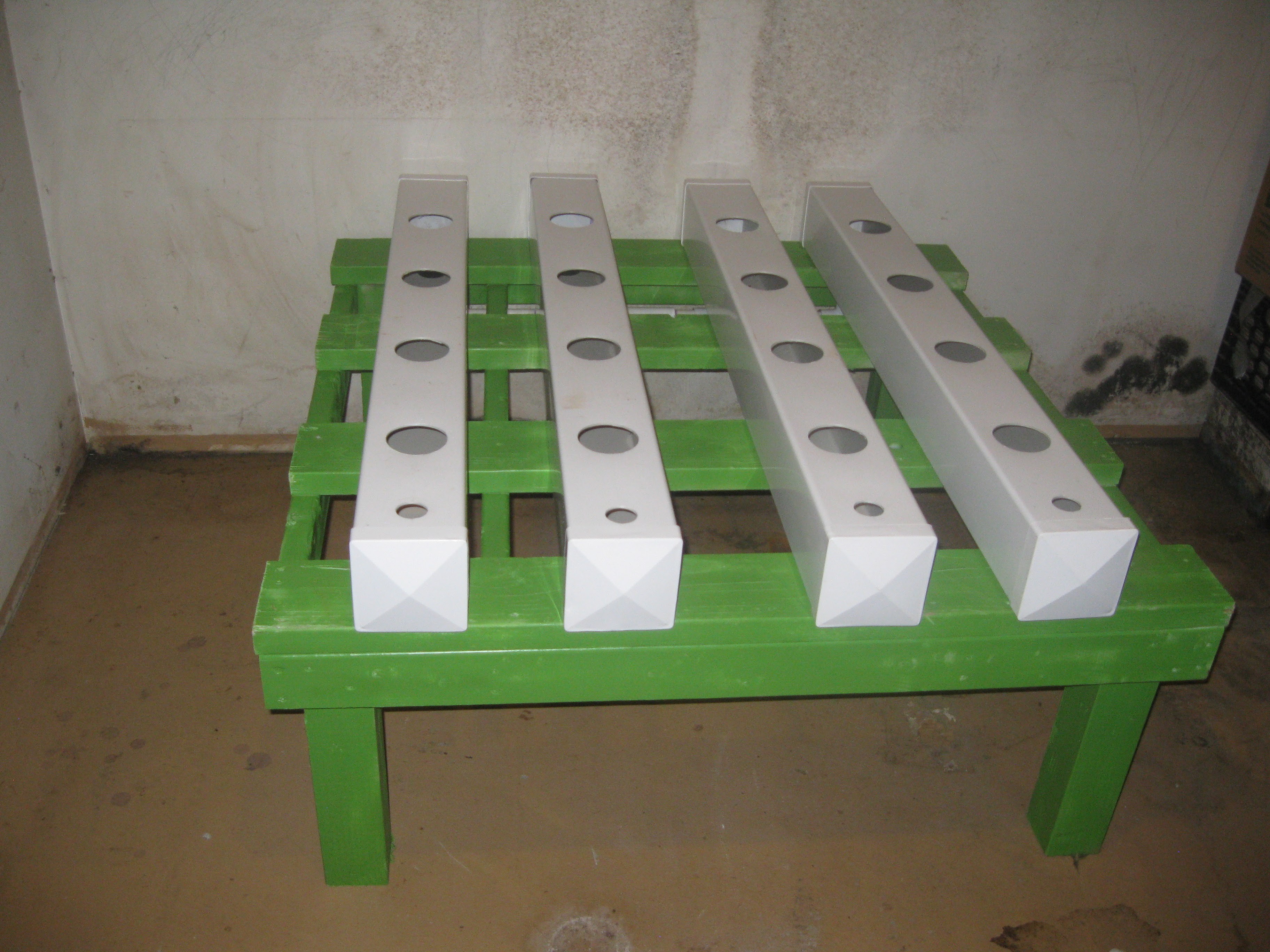
Fence Post Grow Rows installed, they just press fit in place
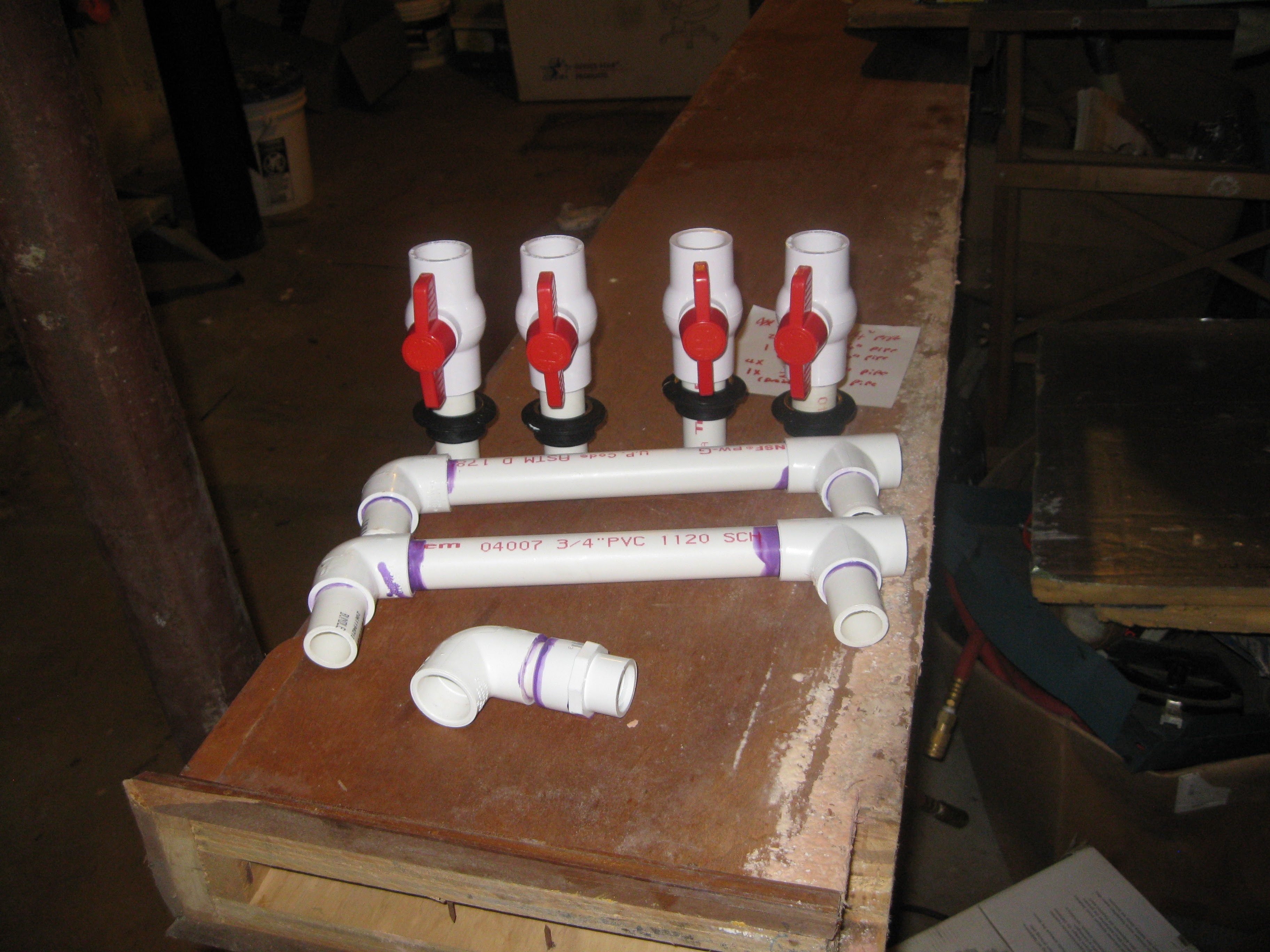
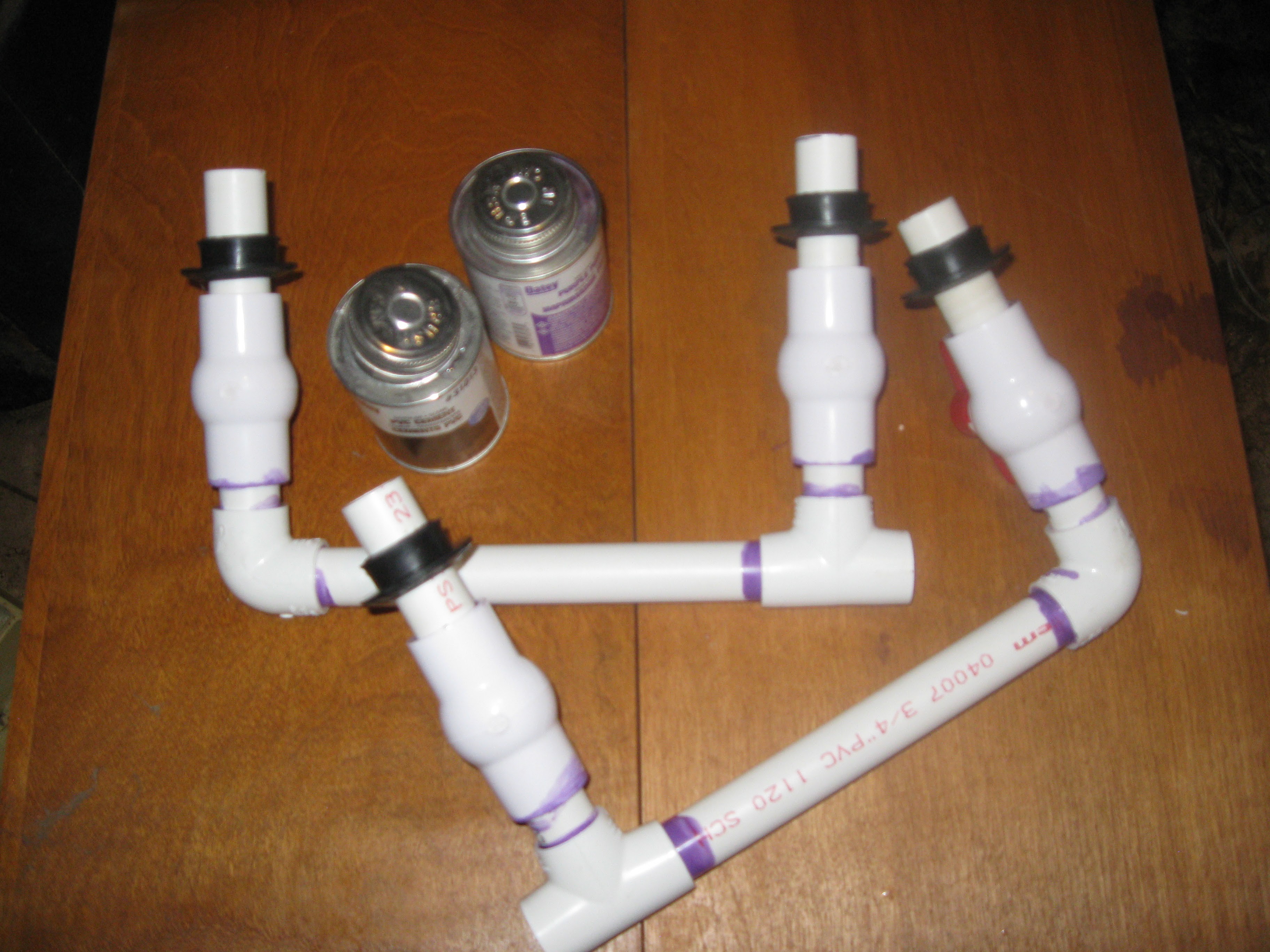
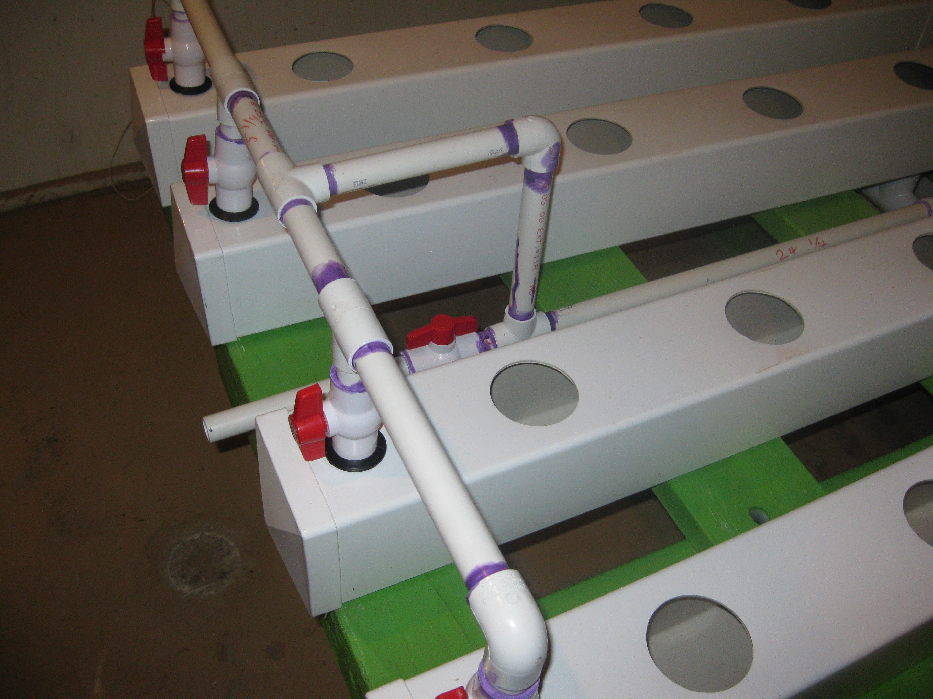
The gluing of the input manifold was a longer more careful process. The input manifold has PVC ball valves for setting the water depth in each row, I decided to assemble the manifold in stages to prevent PVC cement vapor from damaging the valves. As I assembled the manifold I made sure to take down all the lengths of the different pieces of pipe, I will be updating the other project page with this information so anyone out there can build one like mine. Moving on with the photos:
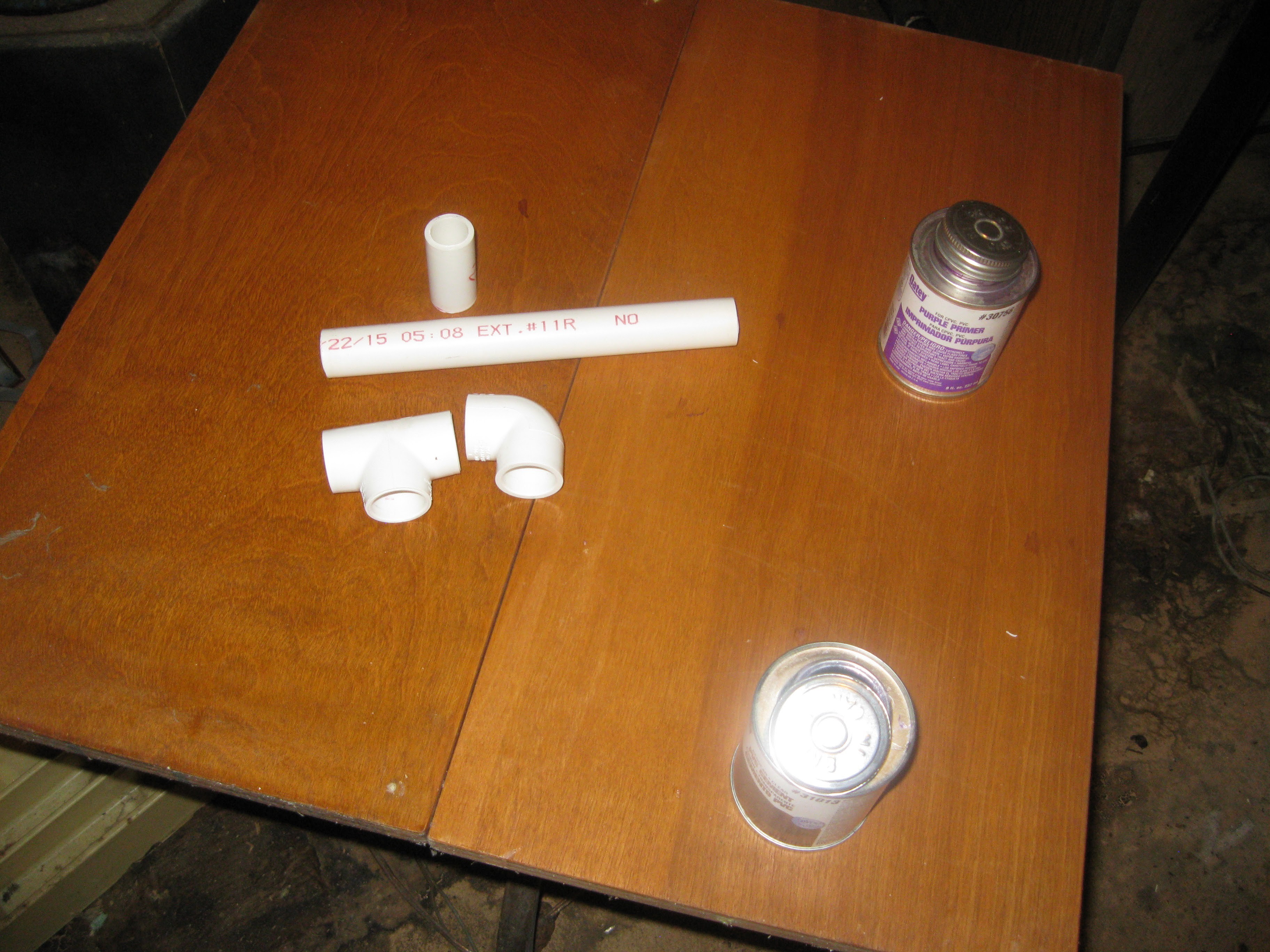
Assembling the t-joining piece
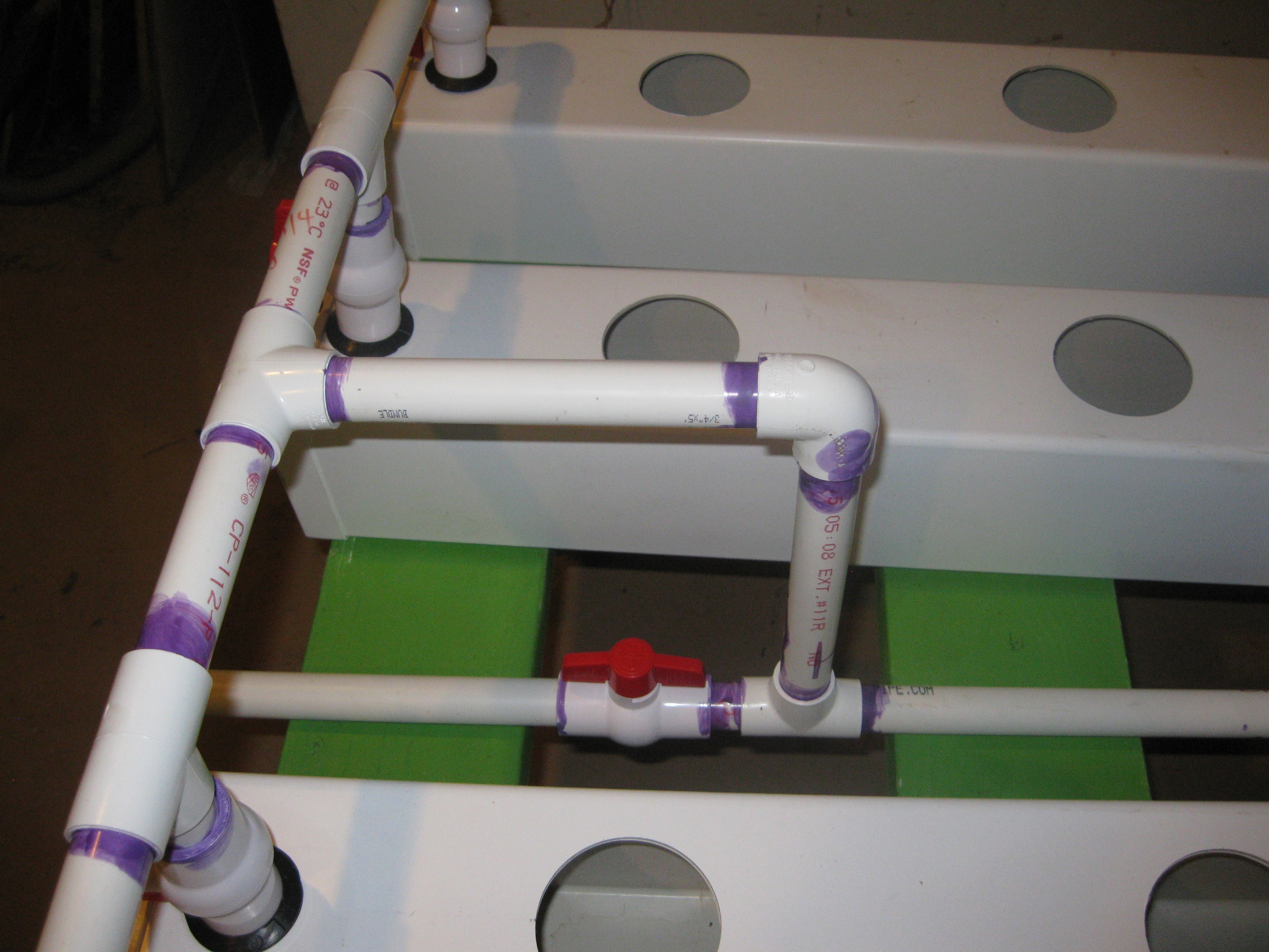
Assembling valve sections of the manifolds. For assembly the manifold was assembled in half essentially, pairing two fence post rows together. Each side of the manifold was assembled separately, with the idea of being installed into place and joined together with the T shaped piece above. This piece is dry assembled here and not yet glued.
Part of section without valves assembled first. The valves and the pipe for connecting them to the fenceposts were assembled separately.
This piece connects the pump and flow rate sensor to the manifold.
Fitting assembly for connecting flow meter to pump and input pipe glued together.

Gluing one of the manifold halves.


Small sections of pipe glued to valves and set to dry, these were attached before gluing the valves into the manifold sections so they would dry a bit before hand to prevent excess vapor of the cement from melting the internals of the valve. Also picture are the two sides of the manifold that the valves glue onto and the fitting assembly for atting the pump and flow meter to the input pipe.
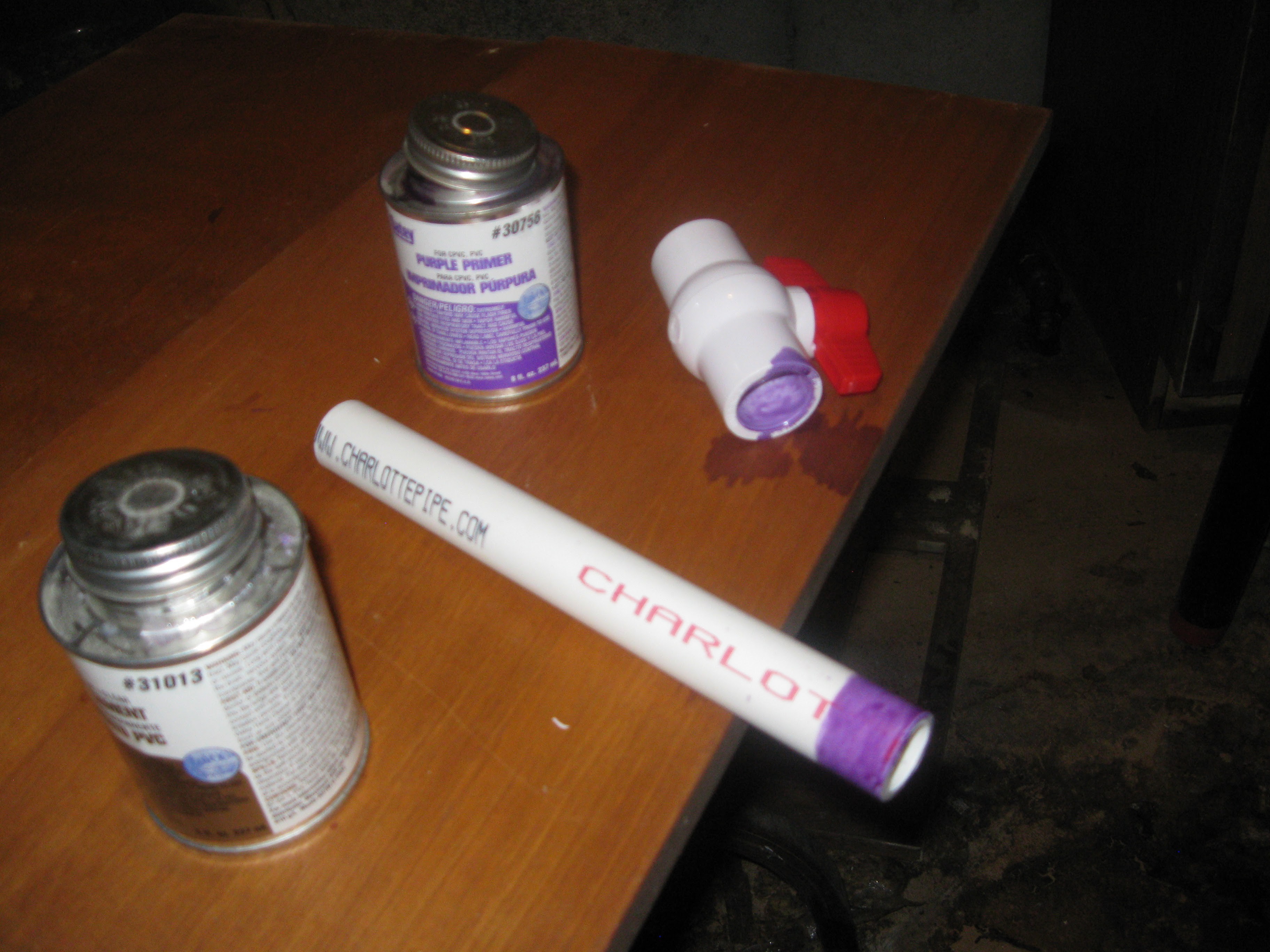
Beginning the input pipe gluing. the input pipe connects the pump inside the reservoir to the T-shape piece designed to join the two halves of the manifold containing the water level set valves.
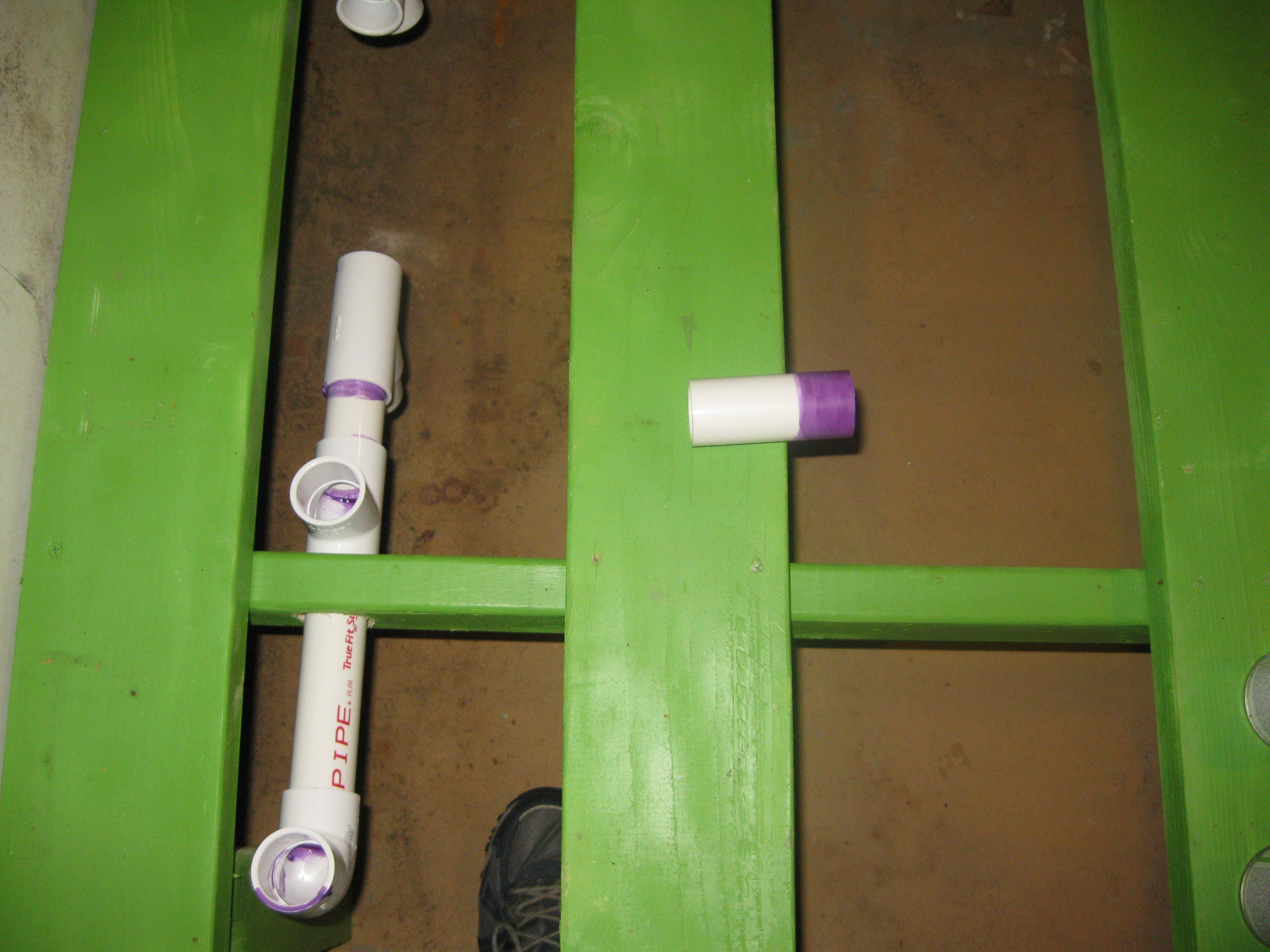
Input pipe assembly components primed for gluing.
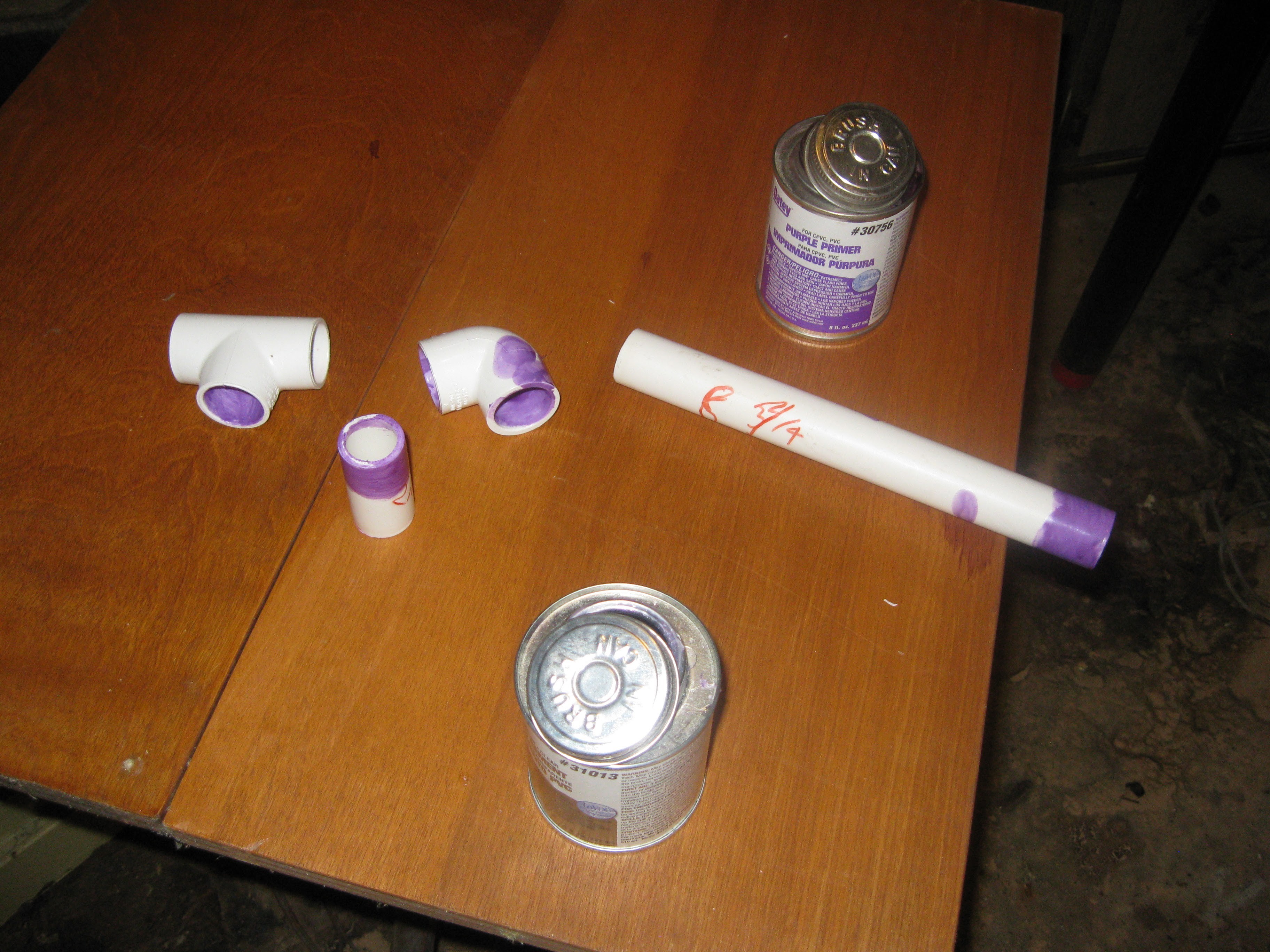
Input pipe assembly in the process of being glued.
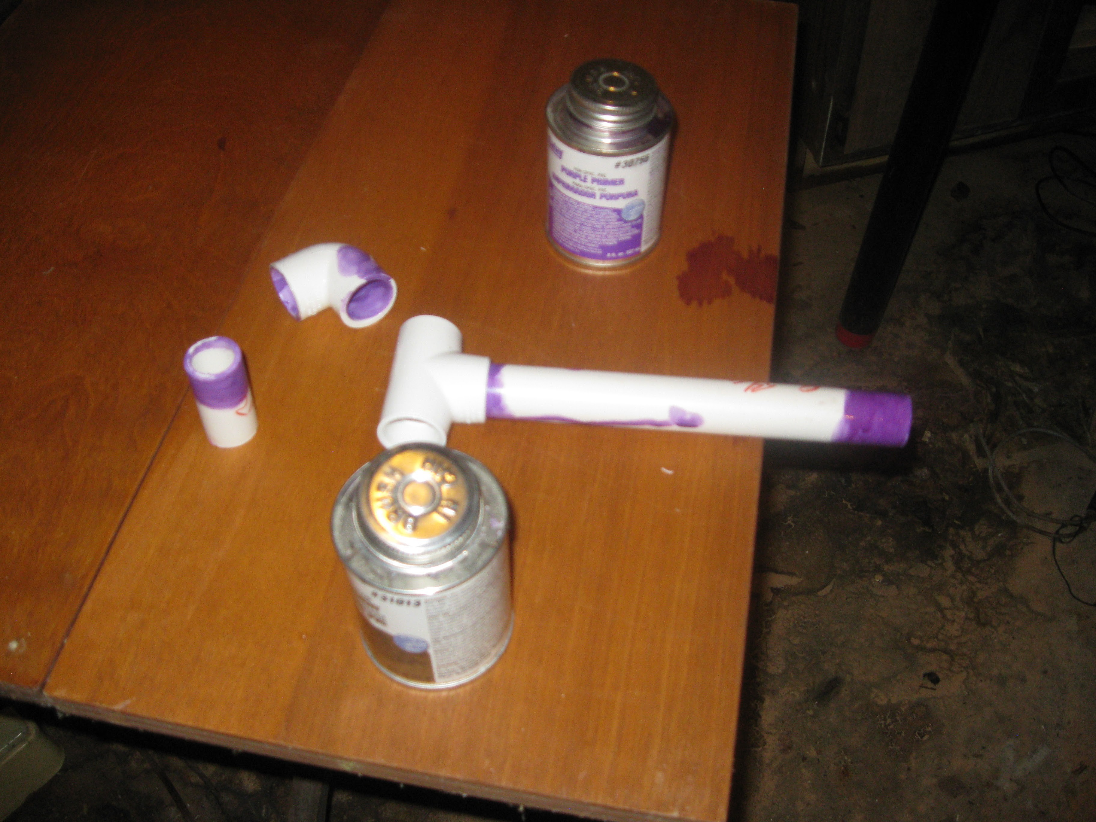
Input pipe and T-shape (joins both sides of manifold) glued and drying for next step.
T-shape piece and input pipe glued together.

Manifold pieces glued in sections, set up to dry briefly before valve gluing.

Pump/flow meter fitting assembly added to input manifold pipe.
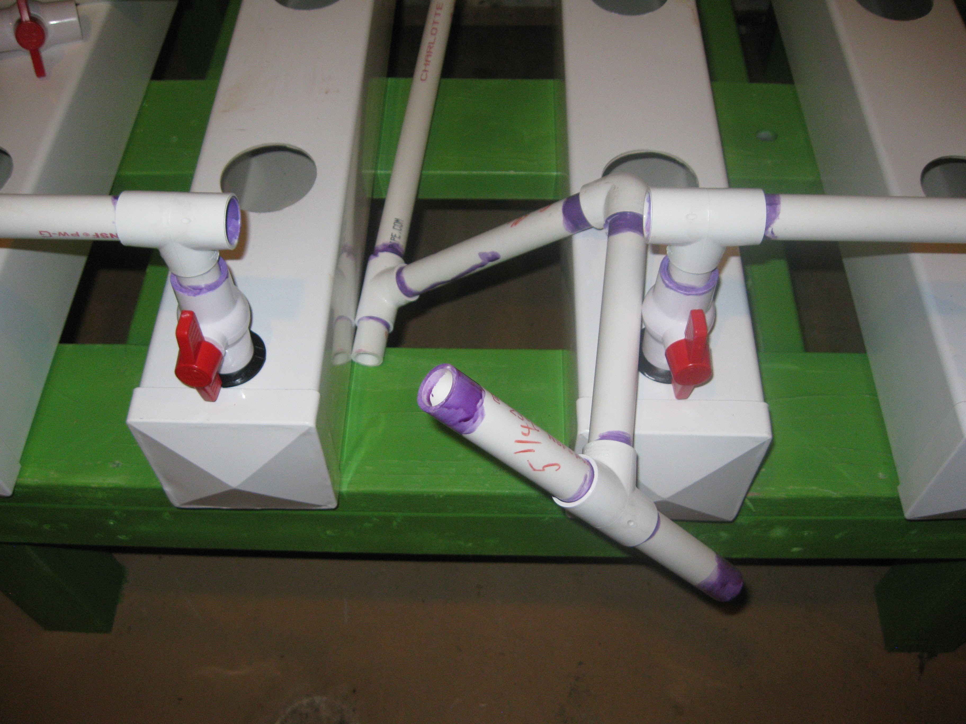
Getting ready to glue the valves onto the two sides of the manifold.
Adding water level set valves to each side of the input manifold.
Two sides of the manifold assembled with valves.
Both completed sections of the manifold placed on either side with the middle T-piece primed and ready for gluing.
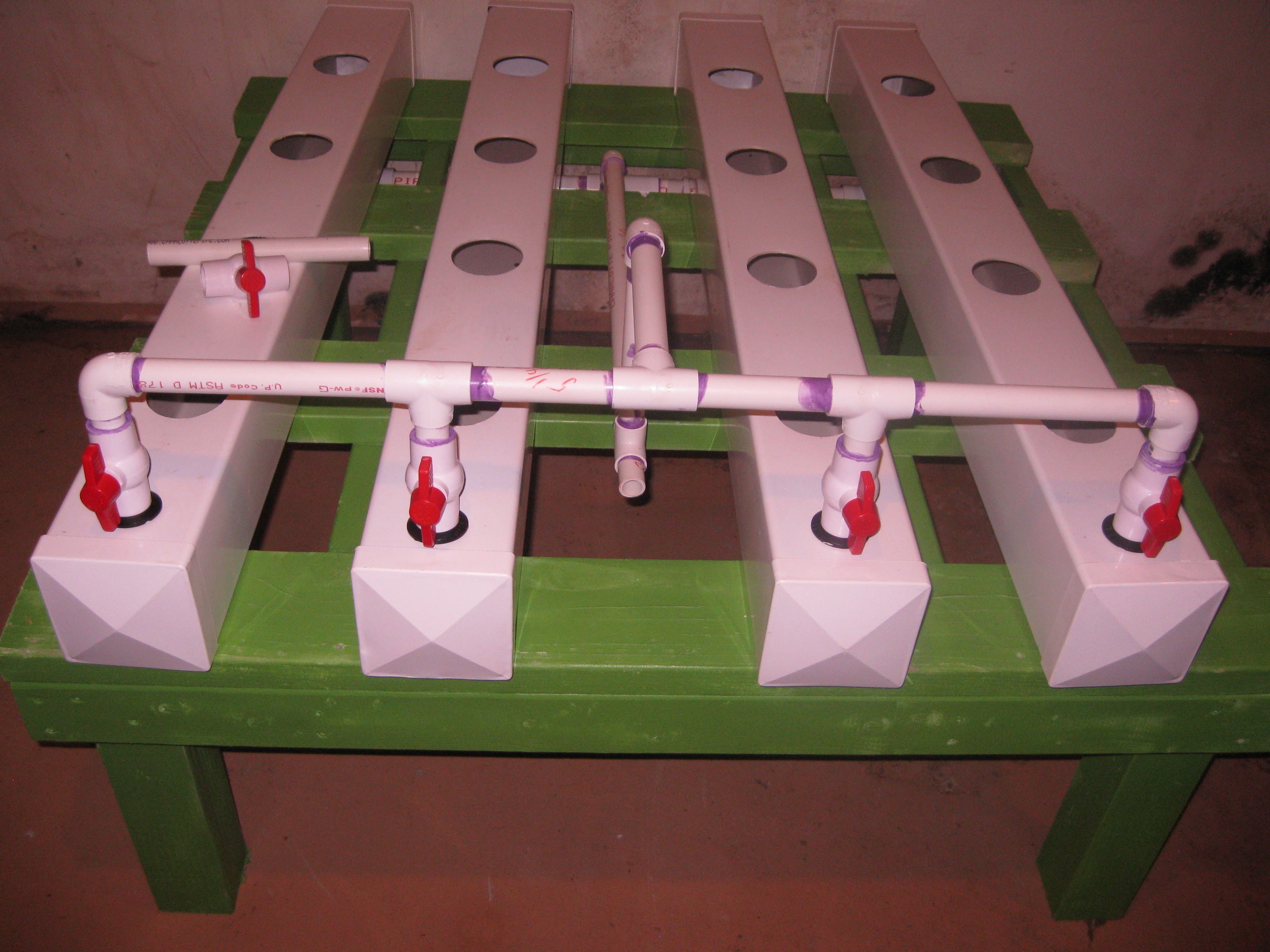
Manifold glued and installed, with the waste water draing valve to be glued in place next.
Gluing the waste water drain valve and pipe
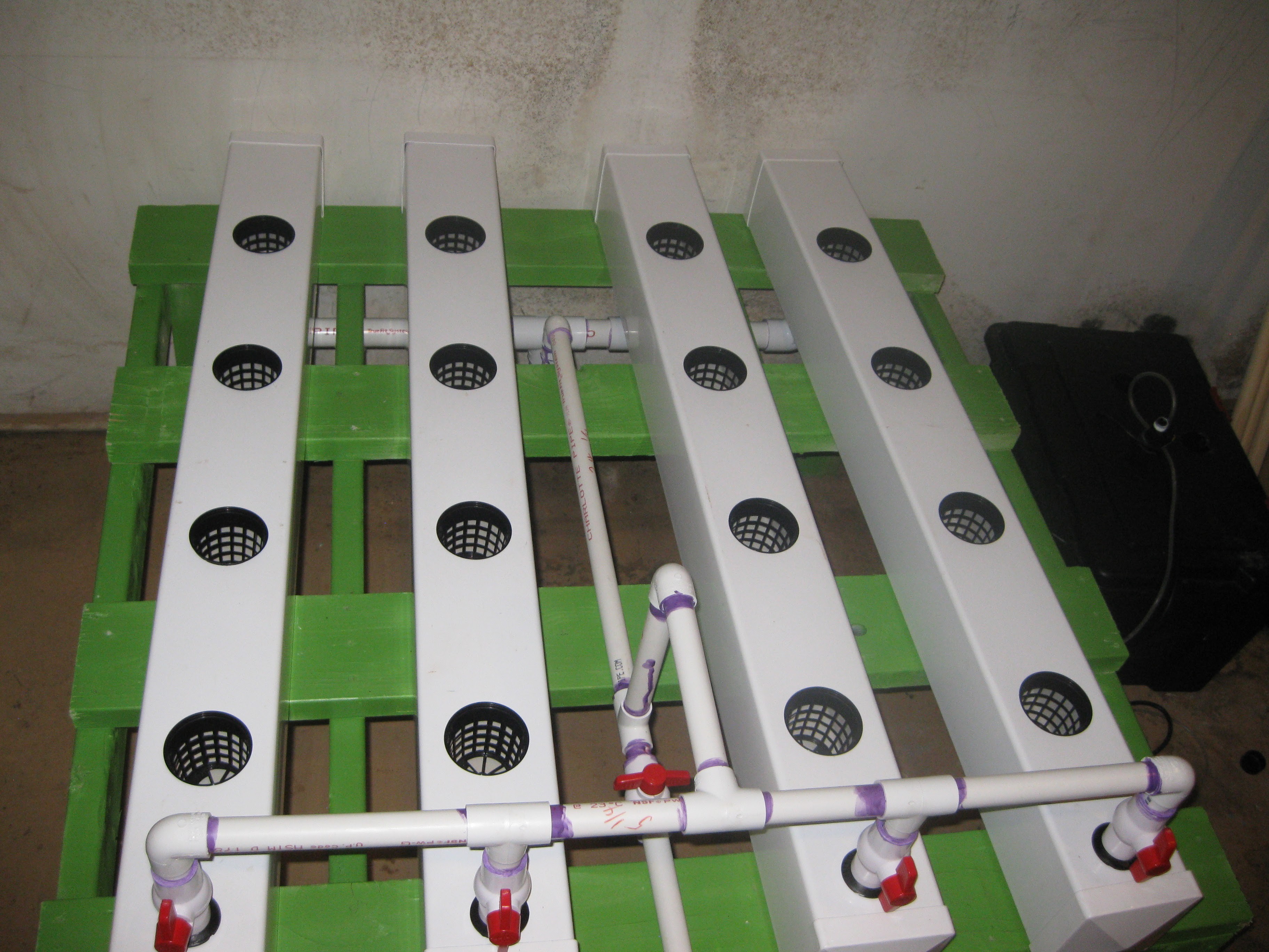
Manifold completely Assembled and installed.
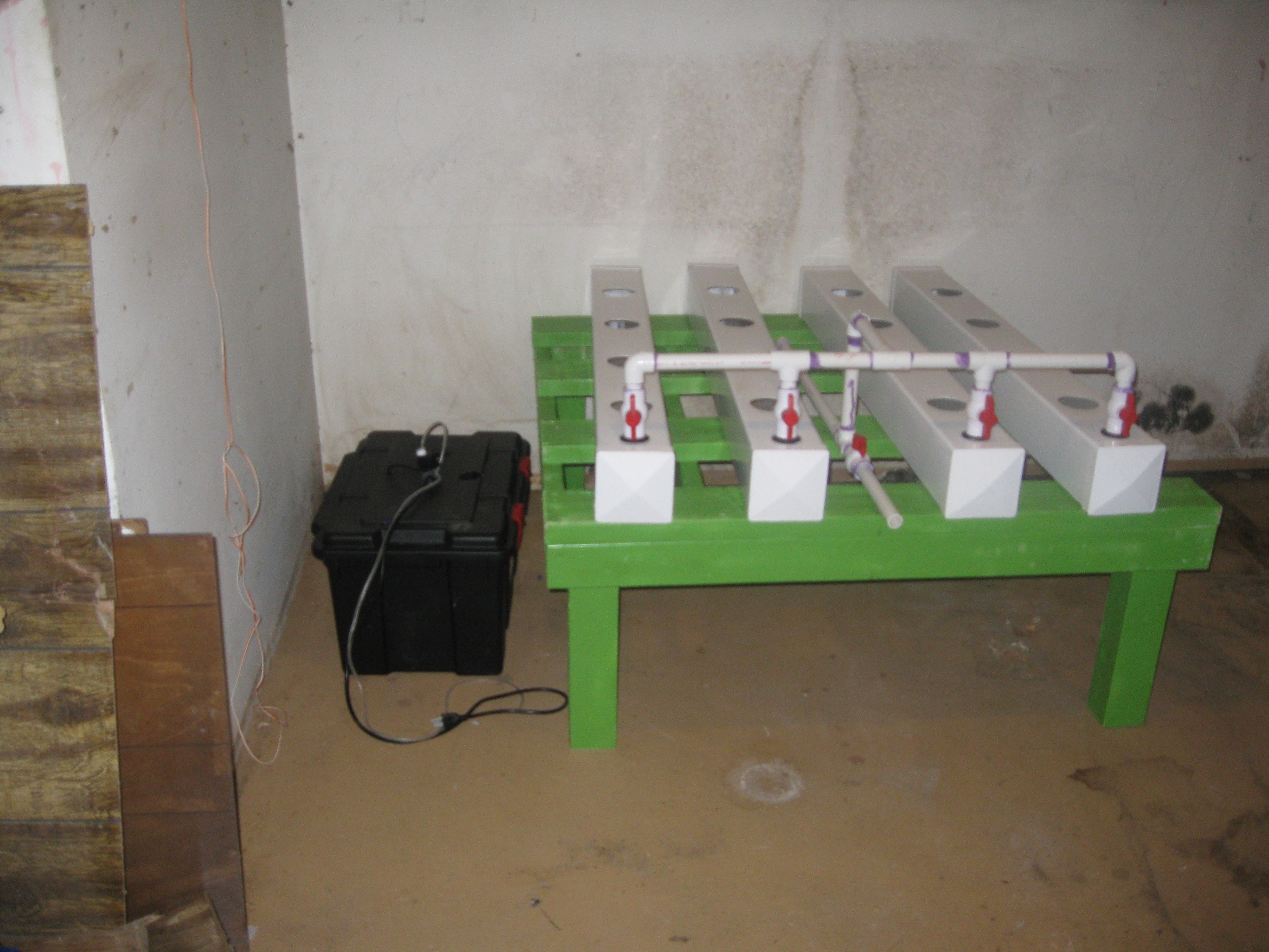
Both manifolds in place, directly above where the reservoir will be placed, perfect.

View from below after both manifolds and fence posts rows installed
Everything in place after moving the rest of the junk out of the space.
Netted pots in place
Discussions
Become a Hackaday.io Member
Create an account to leave a comment. Already have an account? Log In.