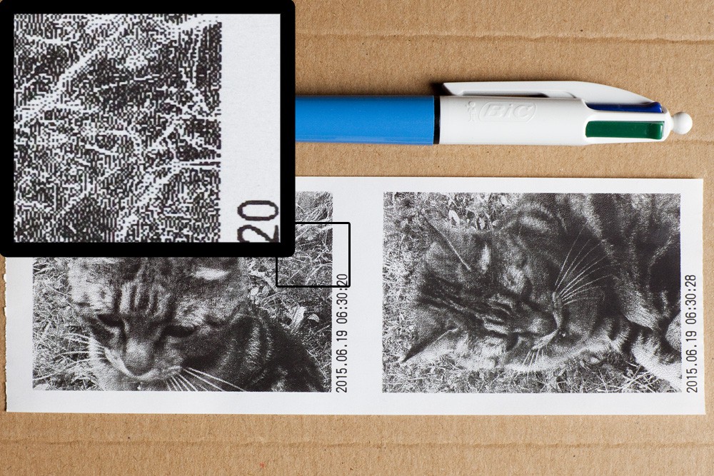
Close
0%
0%

PolaPi

Instant-Printing-Point-and-Shoot camera. Or yet another Polaroid like.

Similar projects worth following
It is an other aspect of the photography to be able to not only show the picture you just took to your friends (on the camera screen), but to physically give the picture.
The aim of this camera is not to make good quality or useful prints. Its give monochrome and tiny prints, but cheap and within few seconds.

It is based on 'affordable easy to find parts' , and Java programming language.

Inspired by the [ch00f] PrintSnap Instant Camera.
http://ch00ftech.com/2014/12/17/printsnap-instant-camera/
The Polatherm Instant Camera.
http://dkia.at/en/projekte/Polatherm

It is worth to mention few facts about the paper. Thermal paper is very cheap and could be easily found without BPA, but it is sensible to sunlight and heat. Exposed to sun, the prints will fade with time.

Results close-up

Hardware

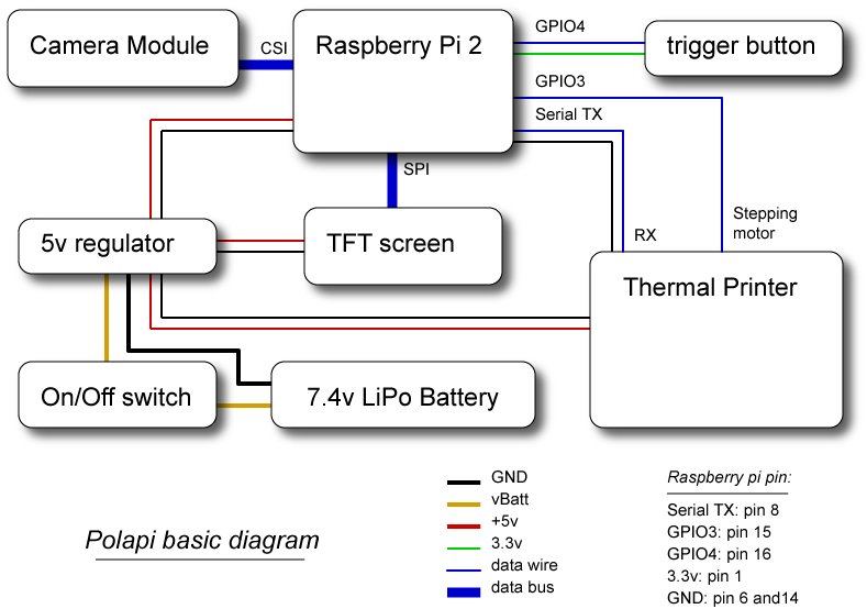
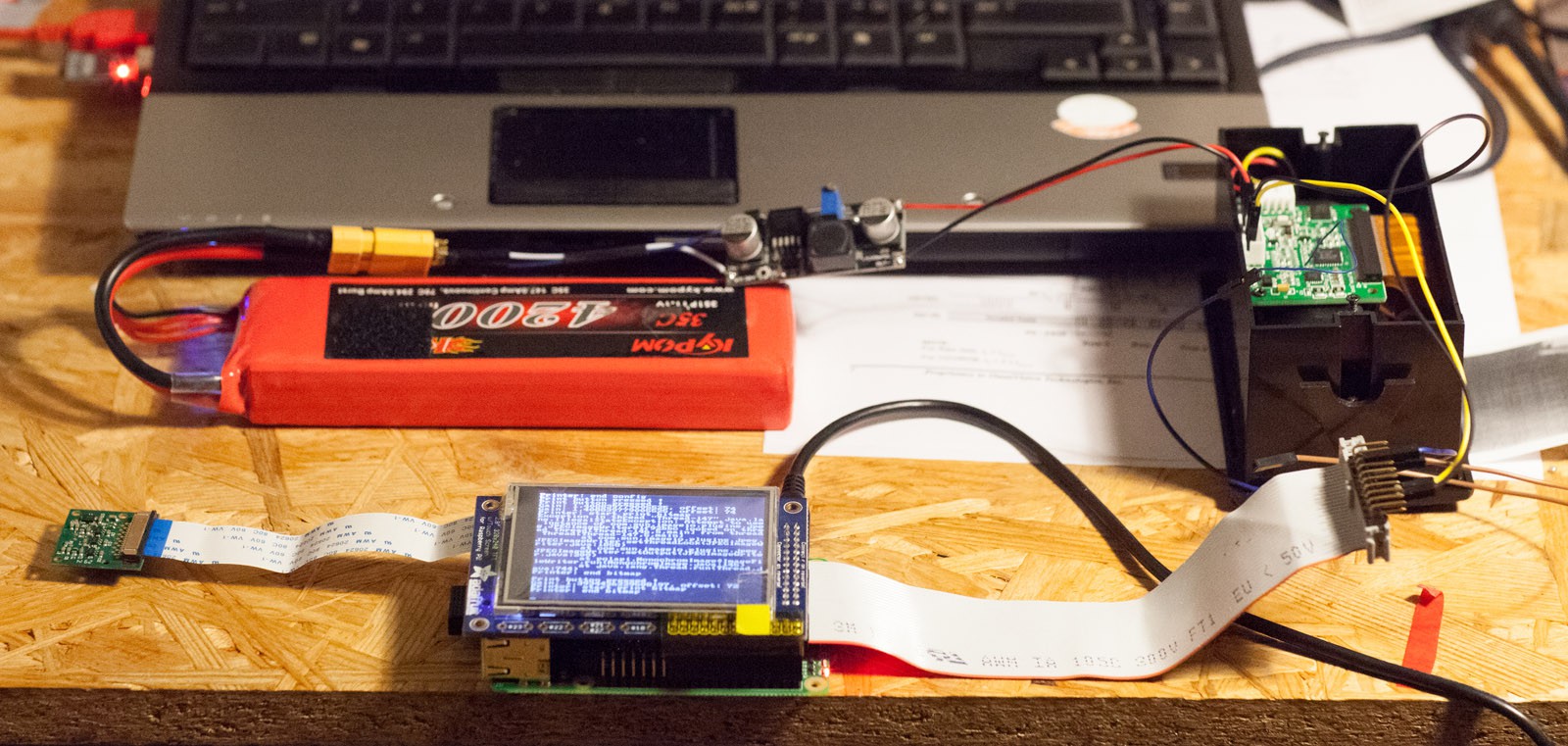
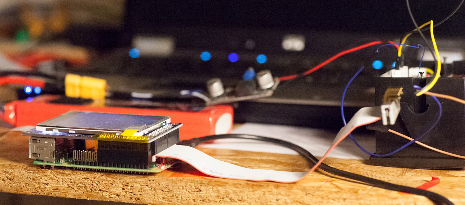
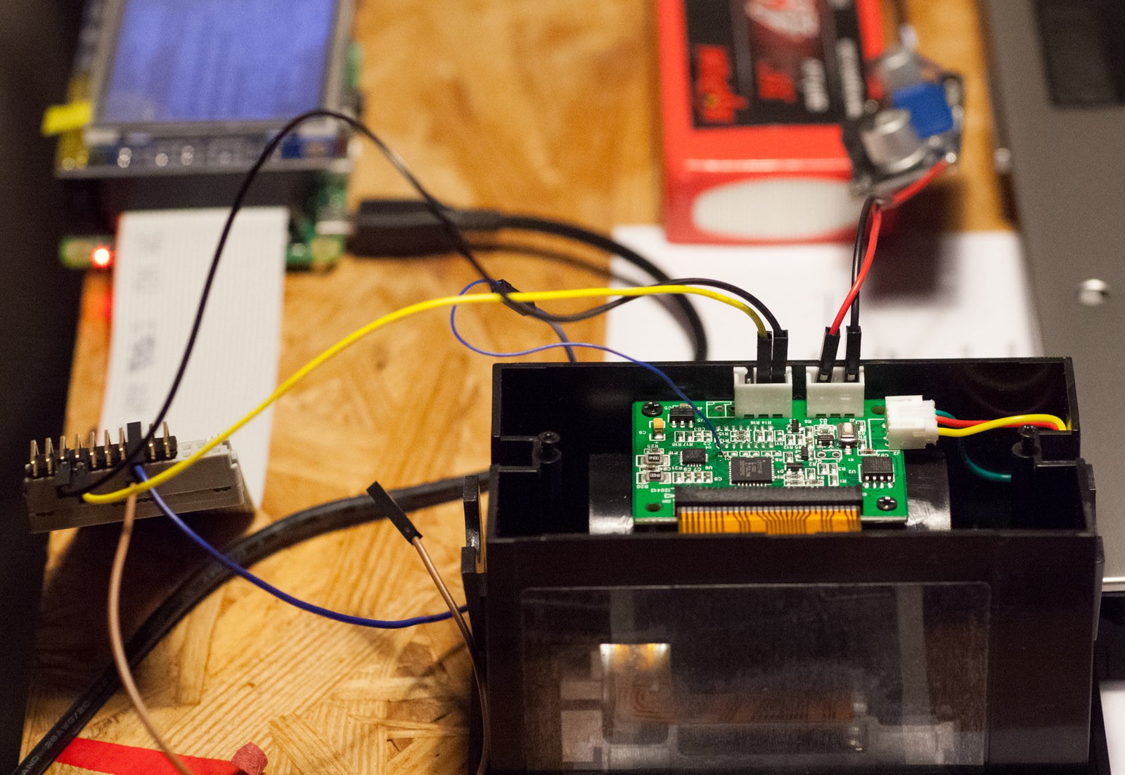
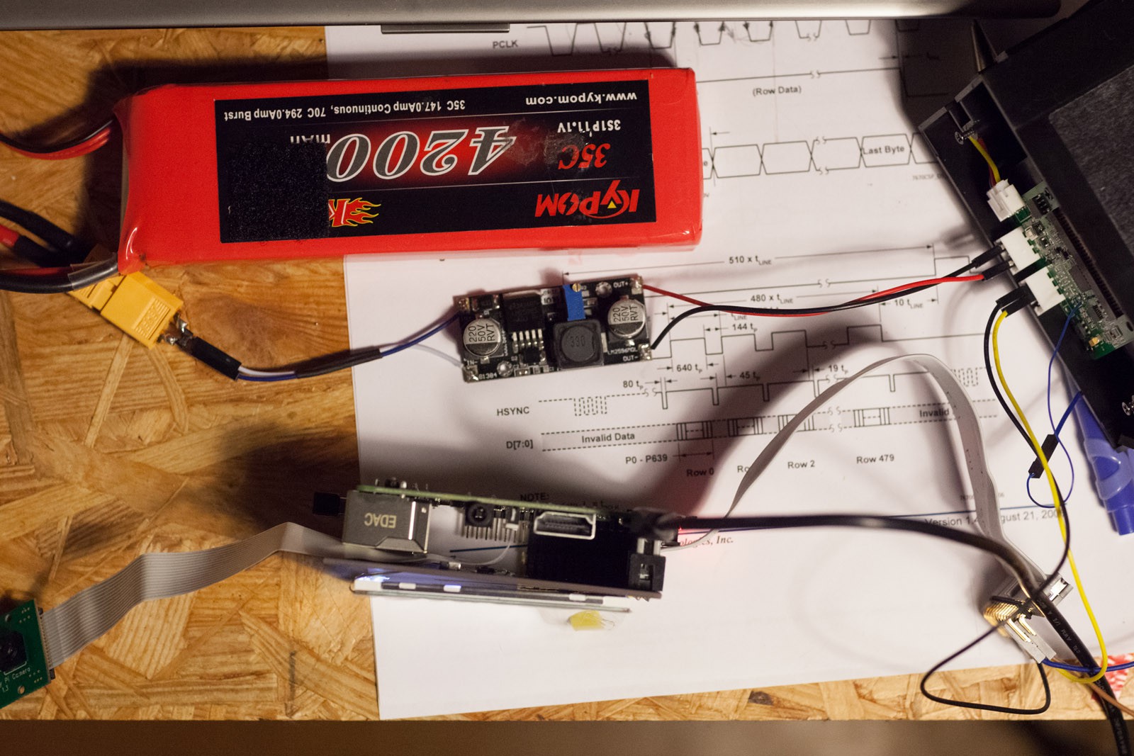
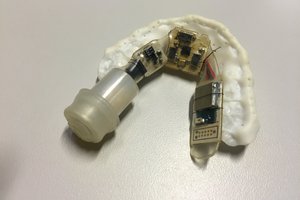
Basic diagram of all the components inside the camera :

(The Raspberry pi pin numbering reference is the one of wiring/pi4j library : http://pi4j.com/pins/model-2b-rev1.html)

Basic diagram

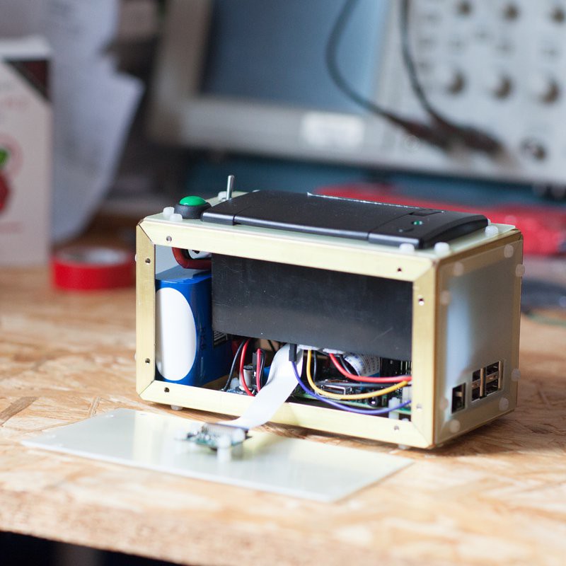
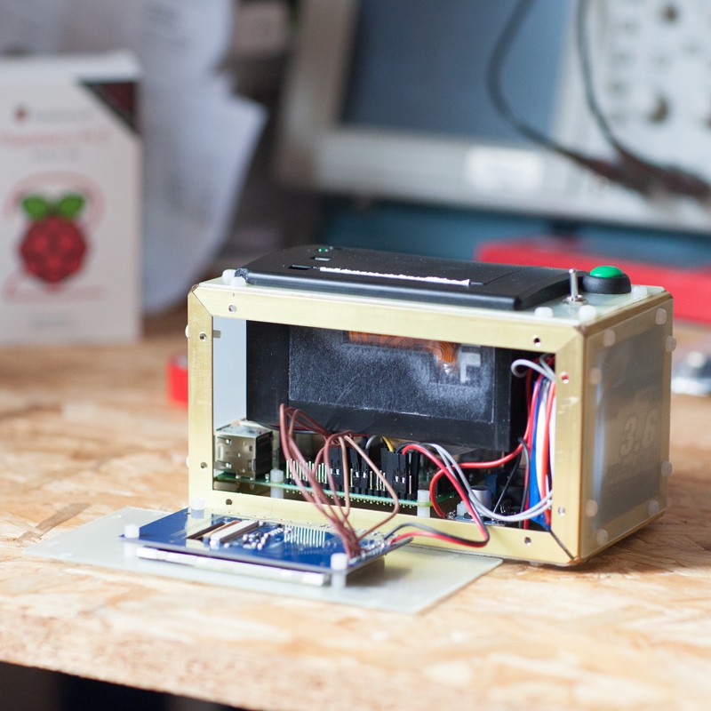
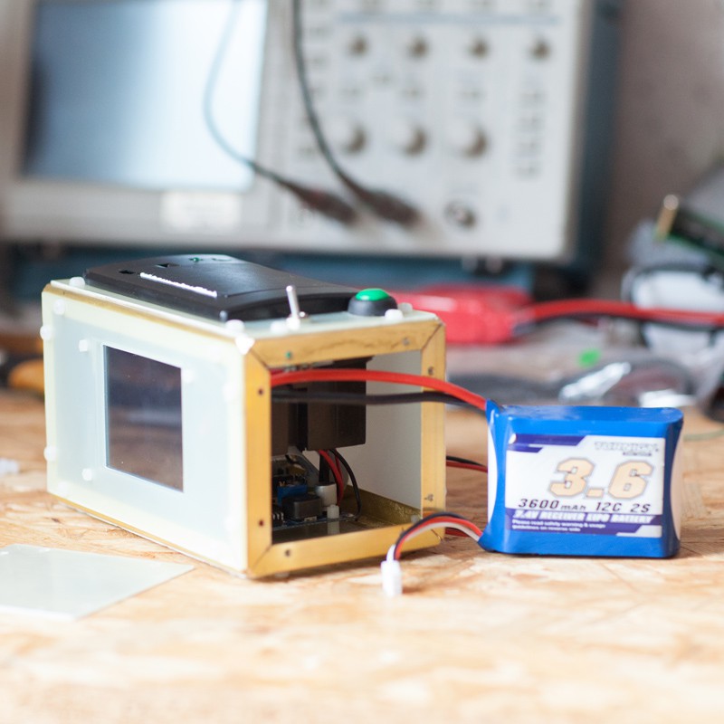
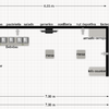
And how they fit in the prototype case :

Software

There is two main external library/executable used by the Java program to achieve picture capturing and printing.

First is the program raspividyuv (in /opt/vc/bin/ of raspbian). It is launched within Java with the argument -o - in order to get the pixels data on stdout in an inputStream.

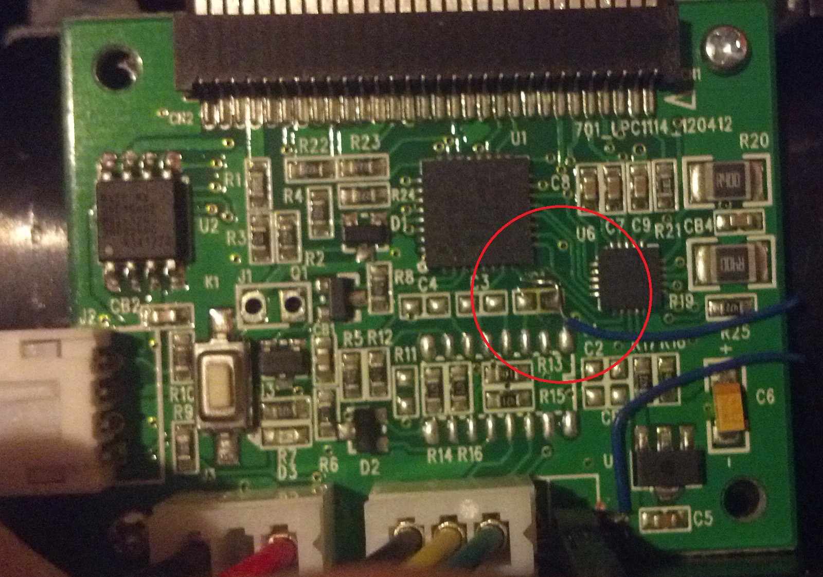
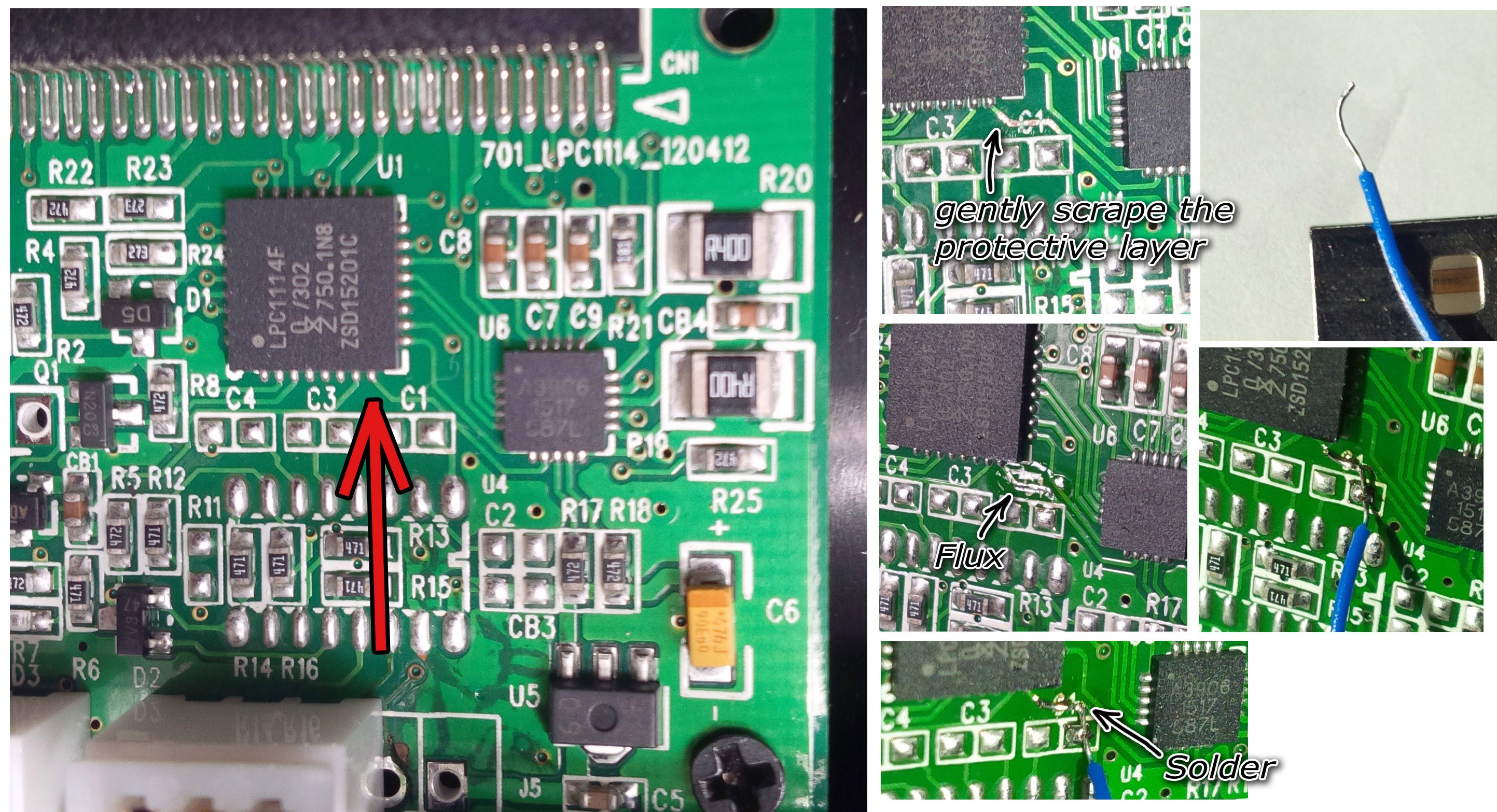
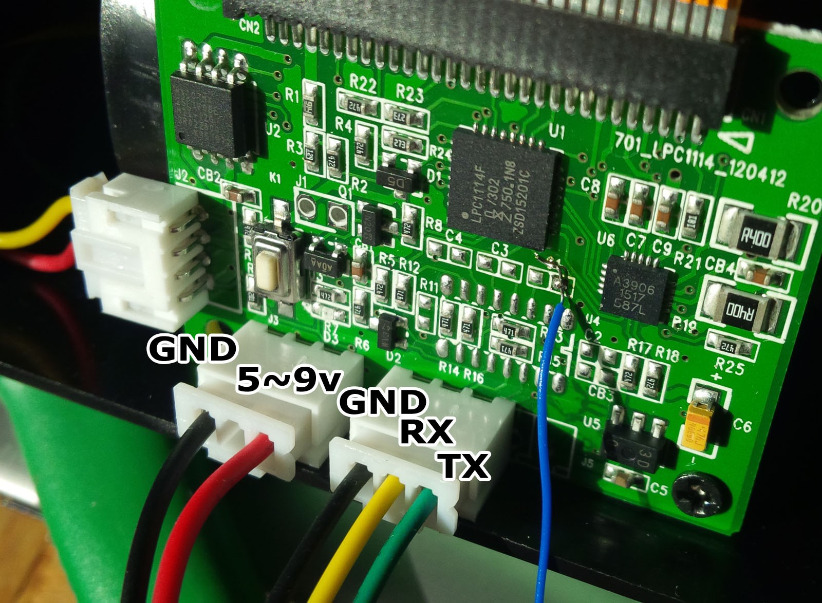
Second is the use of the Pi4J library. The Serial port is configured to send image data to the printer, a GPIO pin is used to read lines advance of the printer and another GPIO for the 'shutter' button event.

Before the Java program starts, the primary frame buffer is copied to the second frame buffer used for the PiTFT screen in order to see the camera preview on it. This is done by the fbcp program. (Credits to tasanakorn)

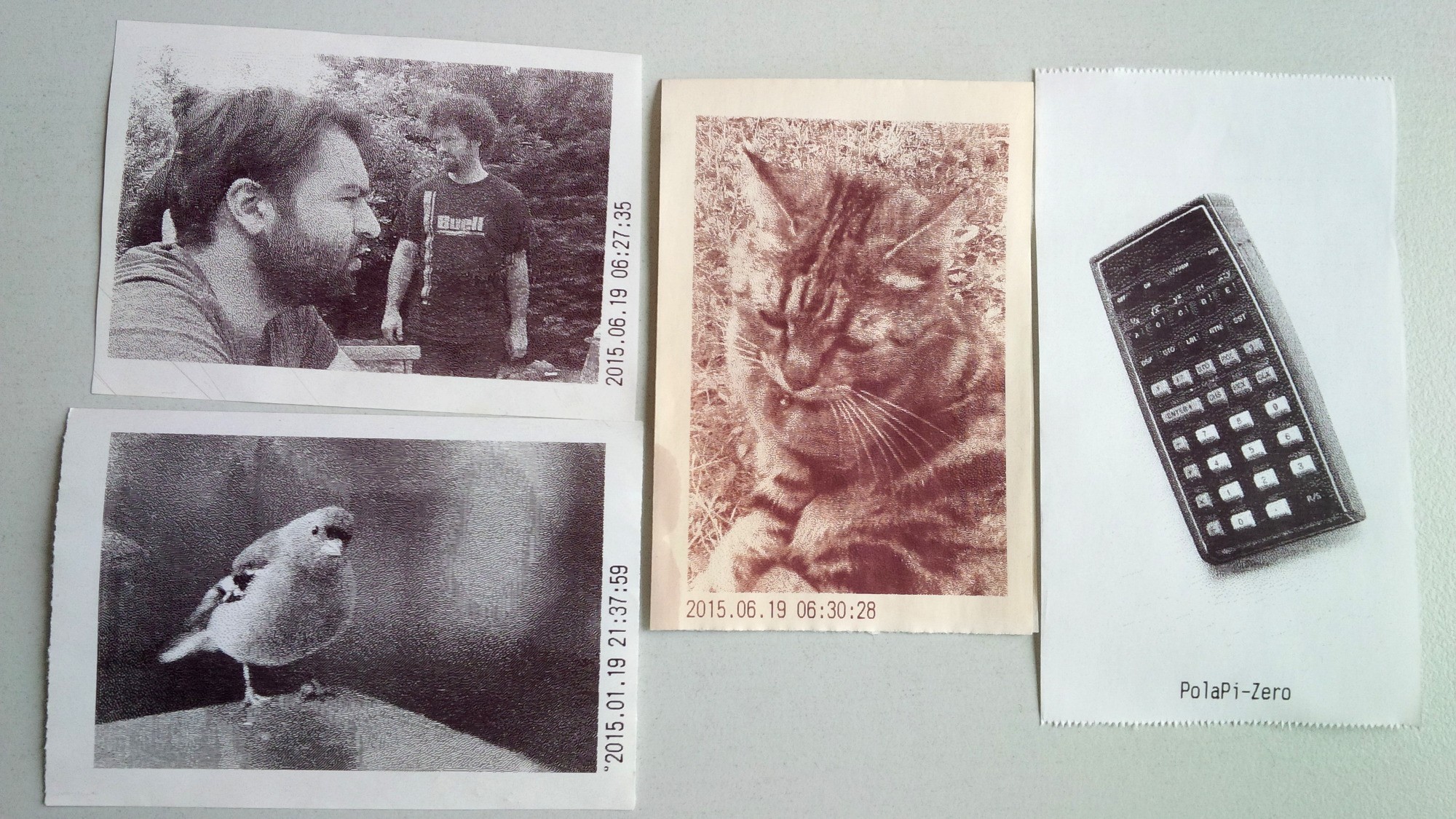
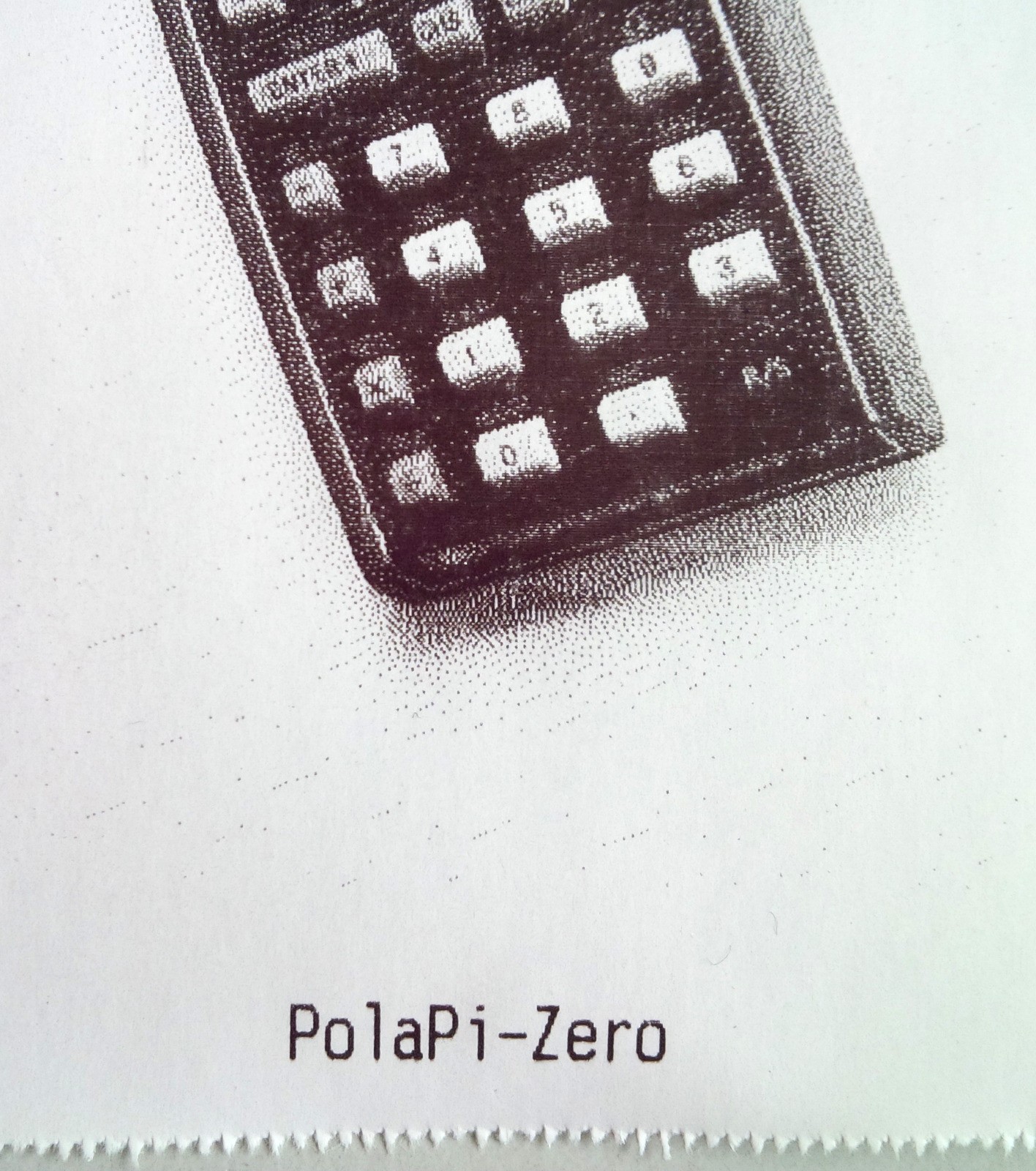
The Java program continuously receive the camera image and build a buffered array of pixels. Once the shutter button is pressed, the event launch two sequential process. The gray-scale image is converted in monochrome with Floyd–Steinberg dithering method. Then the printing thread is started, sending data to the printer on the serial port.

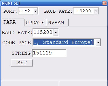
The sources and builds are here on: github. On the jar folder, there is the executable .jar file, the built fbcp program, and the config.txt file. On the last file, there is the welcome message, the header message, the printer serial speed and more configuration detailed in the 7th instruction below.

  • 1 × Basic knowledge about linux, wiring/soldering The printer must be tuned. Files must be put and perhaps edited under RPi linux
  • 1 × Raspberry Pi 2 Works with RPi 1B+ and probably with RPi Zero1.3 but not yet with RPi 3
  • 1 × Raspberry Camera module
  • 1 × Adafruit PiTFT screen (optional) http://www.adafruit.com/product/1601
  • 1 × 57mm Thermal printer http://www.adafruit.com/products/597

View all 11 components

  • Ageing and new version

    Muth02/20/2017 at 12:50 1 comment

    A very short log entry to show how ages the pictures and to link this project with the PolaPi-Zero

    I kept some prints on a desk, close to a windows, and others in a drawer. From left to right, 2 prints from the drawer, one exposed to sunlight behind a windows, and the last one freshly printed with the new version. The dates are correct, the 'old' ones are from mid '15. The papaer is Exacompta 57mm FSC No BPA .

    And a detail

  • Redo for documentation

    Muth12/03/2015 at 20:49 0 comments

    In order to help Neil davis makes a similar camera, I found more simple to redo the entire project from scratch, and take pictures of the steps I missed.

    I added more steps to the instructions part. But I'm sure I can detail more if I have time.

    Here some picture of the test setup :


  • Shared

    Muth10/26/2015 at 10:00 0 comments

    It didn't update this project page for a while now, and I noticed petapixel.com made a nice article about it.

    I would like to say I'm rather impressed how internet could spread something at light speed. It's remind me I forgot to mention this project is of course an educational pretext for myself and it was inspired by plenty of other cameras (commercial and hobby). It is not aimed to be the best quality, the cheapest, the nicer, nor even useful.

    The instructions are not a nice a step by step list, I'll try to put more time on the documentation.

View all 3 project logs

  • 1
    Step 1

    The Thermal Printer

    The most delicate part is to tweak the thermal printer. Some details are there : https://hackaday.io/project/3917-pi-print/log/13184-thermal-printer-adventure . To summarize, there is two step to achieve:

    1 - This printer receives data on a serial port, and by default the speed is slow. And there is a software way to change from 19200 bauds to 115200 thanks to this program: Link. As it is a windows program, we need a USB to 5v TTL serial converter, such as this one. Power the printer, connect the gnd-Tx-Rx, and on the printer program set the right port, the previous speed (19200 in my case), the new speed (115200), code page US (it's the character-set ) and press SET.

    If this step is impossible, see instruction 7.

    2 - The second step is to have a flow control. For the moment, the only way I found is to solder a wire on a pin of the printer's controller chip to get the line paper advance information. I gently scratch the protective layer of the copper track, and solder a wire there.

    Printer Board

    3 - The connections are the following. This little wire from the step motor controller will be connected to the pin15 of the raspberry pi.

    And the printer's RX to the Raspberry pi TX (pin8). Printer's TX is not used.

  • 2
    Step 2

    The Raspberry Pi SD card

    If the adafruit PiTFT screen is used, all linux software steps are described here : https://learn.adafruit.com/adafruit-pitft-28-inch-resistive-touchscreen-display-raspberry-pi/easy-install

    Download the wheezy SD card image and flash-it to the card. Follow the adafruit instruction to install the TFT screen.

    Otherwise, if the regular HDMI/video is used, install the regular Raspbian linux : https://www.raspberrypi.org/downloads/raspbian/

  • 3
    Step 3

    The raspberry camera module connection is documented in the raspberry pi website : https://www.raspberrypi.org/help/camera-module-setup/

View all 8 instructions

Enjoy this project?

Share

Discussions

Georg wrote 11/13/2019 at 16:11 point

Hi,

i try to rebuild this project on an raspberry pi A+. 

PolaPi starting...
/home/pi/polapi/header.txt not found, using config.txt for header text
Unable to determine hardware version. I see: Hardware   : BCM2835
,
 - expecting BCM2708 or BCM2709. Please report this to ...drogon.net

To solve this issue:

Downgrade the kernel to Kernel 4.4.50-v7+ 

sudo rpi-update 52241088c1da59a359110d39c1875cda56496764

If someone use an ILI9341 Display compile the fbcp library:

https://github.com/juj/fbcp-ili9341

Example for an Aliexpress 3,5" 320x240 Display:

cmake -DSPI_BUS_CLOCK_DIVISOR=6 -DILI9341=ON -DGPIO_TFT_DATA_CONTROL=24 -DGPIO_TFT_RESET_PIN=25 -DGPIO_TFT_BACKLIGHT=15 -DSINGLE_CORE_BOARD=ON -DARMV6Z=ON -DBACKLIGHT_CONTROL=ON -DSTATISTICS=0 -DDISPLAY_CROPPED_INSTEAD_OF_SCALING=OFF -DDISPLAY_BREAK_ASPECT_RATIO_WHEN_SCALING=ON ..

Thanks for sharing this project.

  Are you sure? yes | no

Alban wrote 03/25/2018 at 22:02 point

Hi!

Why did you plug the thermal printer at 5v regulator? The printer's manufacturer recommends 5V-9V for the power supply of the printer (with 1.5A). Can I connect the printer directly to an LiPo 7,4V 2A?

  Are you sure? yes | no

varundevang wrote 03/01/2018 at 15:15 point

how much does this project cost

  Are you sure? yes | no

kunal wrote 02/06/2018 at 18:55 point

sorry muth (since my project was over i didnt open this forum ).

earlier i had done without fbcp but now i am getting prob. while using it...

pi@raspberrypi:~/polapi $ sudo java -jar polapi.jar
PolaPi starting...
/home/pi/polapi/header.txt not found, using config.txt for header text
Exception in thread "main" java.lang.reflect.InvocationTargetException
        at sun.reflect.NativeMethodAccessorImpl.invoke0(Native Method)
        at sun.reflect.NativeMethodAccessorImpl.invoke(NativeMethodAccessorImpl.java:62)
        at sun.reflect.DelegatingMethodAccessorImpl.invoke(DelegatingMethodAccessorImpl.java:43)
        at java.lang.reflect.Method.invoke(Method.java:497)
        at org.eclipse.jdt.internal.jarinjarloader.JarRsrcLoader.main(JarRsrcLoader.java:58)
Caused by: java.lang.RuntimeException: Unable to open GPIO direction interface for pin [5]: No such file or directory

        at com.pi4j.wiringpi.GpioUtil.export(Native Method)
        at com.pi4j.io.gpio.RaspiGpioProvider.export(RaspiGpioProvider.java:89)
        at com.pi4j.io.gpio.impl.GpioPinImpl.export(GpioPinImpl.java:158)
        at com.pi4j.io.gpio.impl.GpioControllerImpl.provisionPin(GpioControllerImpl.java:517)
        at com.pi4j.io.gpio.impl.GpioControllerImpl.provisionPin(GpioControllerImpl.java:496)
        at com.pi4j.io.gpio.impl.GpioControllerImpl.provisionDigitalInputPin(GpioControllerImpl.java:591)
        at com.pi4j.io.gpio.impl.GpioControllerImpl.provisionDigitalInputPin(GpioControllerImpl.java:619)
        at com.pi4j.io.gpio.impl.GpioControllerImpl.provisionDigitalInputPin(GpioControllerImpl.java:613)
        at com.pi4j.io.gpio.impl.GpioControllerImpl.provisionDigitalInputPin(GpioControllerImpl.java:636)
        at polapi.Launcher.<init>(Launcher.java:166)
        at polapi.Launcher.main(Launcher.java:198)
        ... 5 more

can you tell me why GPIO pin  is not opening or is their any other prob?

i am trying but dont know how to send picz here,option is not coming!!

  Are you sure? yes | no

kunal wrote 02/12/2018 at 15:35 point

never mind 

started working with tft !! 

:)

  Are you sure? yes | no

Muth wrote 02/13/2018 at 09:23 point

Really sorry kunal, I didn't get the notification of your message, sorry for the delay.

Did you try another GPIO pin for button and motor feedback ? Some screens use GPIO that the Java library then cannot assign.

Hope you have it working now. Don't hesitate to send me a message through hackaday.io instead of this comment section if I'm not replying.

Cheers !

  Are you sure? yes | no

kunal wrote 02/13/2018 at 18:30 point

It's ok muth :) i am actually happy that  you are so much active in helping others to whom you dont even know (in this selfish minded world). sometimes santa can be late but for sure it will come !!

actually it's better  this way as i worked it out without help. That ofcourse increased my knowledge and patient.

For the motor its the same GPIO3 but for the other part instead of using GPIO 4 or 5 I used GPIO 26.Using GPIO 26 allows the printer and the cam to operate but again i wasnt able to find which GPIO pin will work as the button(i was too happy with that only that it started working with the tft ,so i left it till there as i am appearing in INDIAN ARMY SSB interview for which i had to prpare).i will do it tomorrow then i will tell you the whole functioning.

  Are you sure? yes | no

Muth wrote 02/14/2018 at 08:39 point

Great! 
It start to be a long time, I actually don't have anymore this version of the Polapi.
If I remember well, pay attention of the GPIO numbering that you've put in the confix.txt file, it should match with the pi4j.com library : http://pi4j.com/pins/model-2b-rev1.html
Cheers

  Are you sure? yes | no

kunal wrote 01/29/2018 at 05:50 point

Hello muth!!

I am doing the same project and i am close to the end.it's just my camera is starting but its not taking pic after this command...even after connecting GPIO pins(checked both GPIO 4 &5 its not working)?

cd /home/pi/polapi/
pi@raspberrypi:~/polapi $ sudo java -jar polapi.jar
PolaPi starting...
/home/pi/polapi/header.txt not found, using config.txt for header text
Opening /dev/ttyAMA0 at 19200 bauds.
Printer: start config
Printer: end config
start camera

seperately my printer and camera module are all working properly.

but here my printer is ending its work after my camera starts?why so?

what to do next?please help me out!!

  Are you sure? yes | no

kunal wrote 01/29/2018 at 09:44 point

let it be muth!! 

got it!!

its done.its working. :)

  Are you sure? yes | no

Muth wrote 01/29/2018 at 13:58 point

Wow, that was fast ! I'm really glad you've found the issue and you got it working !
Put some pictures of your build here ! I'm curious to see other's builds.
Congrats! 

  Are you sure? yes | no

Oscar Lindgren wrote 09/22/2016 at 11:53 point

Hello Muth!! 
I'm having problems running the "polapi.jar" file. After running sudo java -jar /home/pi/polapi/polapi.jar I get the error message "Invalid or corrupt jarfile". I've tried updating oracle-java7-jdk to no help. I'm relativly new to rasbian but I can't understand why it doesn't want to work. 

Do you have any ideas? 

Thank you for your great guide!! 


  Are you sure? yes | no

Oscar Lindgren wrote 09/22/2016 at 14:43 point

I reinstalled the OS and that allowed me to launch the program however I got this message instead

"Error in config.txt/home/pi/polapi/header.txt not found, using config.txt for header textOpening /dev/ttyAMA0 at 0 bauds.Printer: start configstart camera

Exception in thread "Thread-2" java.lang.IllegalStateException: Serial connection is not open; cannot 'write(char)'.
at com.pi4j.io.serial.impl.SerialImpl.write(SerialImpl.java:169)
at polapi.ThermalPrinter$PrinterConfigThread.run(ThermalPrinter.java:96)"


I'm using a HDMI display if that changes anything. 
Any tips?? 

  Are you sure? yes | no

Muth wrote 09/23/2016 at 13:09 point

Hi !

I'm sorry it not launched without problem. It seems the serial port speed was not properly setup with the value in the config.txt file.
Did you put the config file https://raw.githubusercontent.com/pierre-muth/polapi/master/jar/config.txt at /home/pi/polapi/config.txt ?

Hope that helped, anyway do not hesitate.

  Are you sure? yes | no

Danii2231212 wrote 07/04/2016 at 18:36 point

Hello Muth!! First of all thanks you for explaining this awesome project step by step, i am sure you have introduced some photoNerds like me into electronics. 

I am pretty noob and i am already stuck at step 1 :(  !! ..i bought all components you listed, the only difference is that i bought the tiny thermal printer and i dont know how to have the flow control of it.

The problem is  I dont know wich pin is the one I should solder the wire to.

http://imgur.com/a/a3goe

It may be as simple as conect it via USB to the Rasperry Pi, but i want to make sure before i start with linux.

Do you have any ideas? Thank you and sorry for my english

  Are you sure? yes | no

Muth wrote 07/05/2016 at 16:48 point

Hi !

Unfortunately I never tested this printer model. It could be if you connect the USB, it behave as a serial port. You can try to see if a device appears in /dev.

I didn't see any button on this model, do you have a way to print the config ? On the other models, we should press the button before powering the printer. On this page there is the serial com speed. If it is something like 19200 or 9600, there is a chance you don't need to solder a pin to control the line advance.

No problem with your english, mine is far to be perfect.

  Are you sure? yes | no

Danii2231212 wrote 07/06/2016 at 18:15 point

Hello Muth,  the tiny thermal printer came with this:


Is this a win? I thought i needed a  115200 baudrate

thanks for your quick response, i dont lose faith in finishing it, i ll write about my progress with the tiny thermal printer: https://www.adafruit.com/product/2751

  Are you sure? yes | no

Muth wrote 07/06/2016 at 20:09 point

Hi !

I added recently an option in the config file to set the serial speed, such as 9600 bauds, so it might work. The issue of lower speed is prints will take a longer time and the printer usually make some pause, resulting horizontal artifacts. However I never test this printer, I can guaranty it'll work :/

  Are you sure? yes | no

12blues wrote 06/20/2016 at 22:04 point

Sheesh, This is all really hard to read. Totally need some help with anyone who could translate this to someone who is a true noob. 

  Are you sure? yes | no

monoroto wrote 06/15/2016 at 20:24 point

Muth, thanks for posting this project. I started the build, but the software instructions you posted are a little vague for me (I am relatively new to Linux and python) and probably intended for advanced users. Any chance you could post some more detail regarding software installation and config? Thanks

  Are you sure? yes | no

Muth wrote 06/16/2016 at 07:57 point

Hello Monoroto,
Yes sorry I should have specify some linux basics is needed there. Actually I'm not an expert in python but more confident with Java, that's why I used this language.
Could you tell me where are you stuck ? It'll be more easy for me to help you.

  Are you sure? yes | no

monoroto wrote 06/18/2016 at 03:06 point

Hi Muth, well I completed up to step 7 and downloaded fbcp, polapi.jar and config.txt into the created folder. Rebooted and just goes to command prompt.I have the hardware set up as specified.

The raspberry pi could be accessed with ssh and files copied with scp (or winscp).
Make the following folders:
/home/pi/Photos (where the picture files will be saved)
/home/pi/polapi
On the last one, put 3 files. The file fbcp (if not executable, use "chmod +x fbcp"). The file polapi.jar. And make a text file "config.txt" which contains configuration information. You can download it directly here on github.

  Are you sure? yes | no

Muth wrote 06/18/2016 at 06:16 point

Hi !
All right, I think you are quite close. Do you use the PiTFT screen ?

Anyway, you can yet test if the program runs correctly. In a terminal go to the /home/pi/polapi/ folder and type "sudo java -jar polapi.jar". 
The camera output is on the HDMI screen, so if you have the SPI screen it might not appear. But you can still press the 'trigger' button and check if there is no bugs. Let me know the program output.

To makes everything running at startup you have to edit the /etc/rc.local file. At the end of the file, add the 3 lines of the last instruction:

cd /home/pi/polapi/
./fbcp &
sudo java -jar polapi.jar

If you don't have the spi screen, don't put the line ./fbcp &

  Are you sure? yes | no

monoroto wrote 06/19/2016 at 04:38 point

pi@raspberrypi:~/polapi $ sudo java -jar polapi.jar

PolaPi starting...
/home/pi/polapi/header.txt not found, using config.txt for header text
Exception in thread "main" java.lang.reflect.InvocationTargetException
        at sun.reflect.NativeMethodAccessorImpl.invoke0(Native Method)
        at sun.reflect.NativeMethodAccessorImpl.invoke(NativeMethodAccessorImpl.                                                                                                 java:62)
        at sun.reflect.DelegatingMethodAccessorImpl.invoke(DelegatingMethodAcces                                                                                                 sorImpl.java:43)
        at java.lang.reflect.Method.invoke(Method.java:497)
        at org.eclipse.jdt.internal.jarinjarloader.JarRsrcLoader.main(JarRsrcLoa                                                                                                 der.java:58)
Caused by: java.lang.RuntimeException: Unable to open GPIO direction interface f                                                                                                 or pin [4]: No such file or directory


        at com.pi4j.wiringpi.GpioUtil.export(Native Method)
        at com.pi4j.io.gpio.RaspiGpioProvider.export(RaspiGpioProvider.java:89)
        at com.pi4j.io.gpio.impl.GpioPinImpl.export(GpioPinImpl.java:158)
        at com.pi4j.io.gpio.impl.GpioControllerImpl.provisionPin(GpioControllerI                                                                                                 mpl.java:517)
        at com.pi4j.io.gpio.impl.GpioControllerImpl.provisionPin(GpioControllerI                                                                                                 mpl.java:496)
        at com.pi4j.io.gpio.impl.GpioControllerImpl.provisionDigitalInputPin(Gpi                                                                                                 oControllerImpl.java:591)
        at com.pi4j.io.gpio.impl.GpioControllerImpl.provisionDigitalInputPin(Gpi                                                                                                 oControllerImpl.java:619)
        at com.pi4j.io.gpio.impl.GpioControllerImpl.provisionDigitalInputPin(Gpi                                                                                                 oControllerImpl.java:613)
        at com.pi4j.io.gpio.impl.GpioControllerImpl.provisionDigitalInputPin(Gpi                                                                                                 oControllerImpl.java:636)
        at polapi.Launcher.(Launcher.java:159)
        at polapi.Launcher.main(Launcher.java:191)
        ... 5 more

  Are you sure? yes | no

Muth wrote 06/19/2016 at 06:41 point

Hello, 


Thanks for the raw program output. I presume you are using a SPI screen (Am I right ?) Some linux setup uses GPIO pins for the screen, so the Java lib could not access to these in particular. I cannot predict which one is left free without knowing the screen you're using, but there is a way to setup the java program to use other pins.
Apparently the GPIO4 (pin16) is already used:

"Unable to open GPIO direction interface for pin [4]: No such file or directory"

So for the trigger button which is using GPIO 4 you have to exchange to another one. Let's try GPIO 5 (pin18). To do so, 

 - move the trigger button wire from pin16 to pin18 according this layout: http://pi4j.com/pins/model-2b-rev1.html

- edit the file config.txt, and after the line "BUTTONPIN:" replace the '4' by a '5'

It is still possible to get errors if either the motor pin (GPIO 3) is not free or GPIO 5 as well. So then we have to find which pins are free in your case.

Cheers

  Are you sure? yes | no

monoroto wrote 06/19/2016 at 16:14 point

Hi Muth, thanks for your quick response. I should have clarified, I am using the new pi zero board with camera header and an Adafruit PiTFT 2.8 . I was able to reassign the trigger to GPIO 1 (pin 12) and the other lead to 3.3v. I assume fbcp buffer is working as I can now see console (same as hdmi output) on the pitft spi lcd. Here is the output I get when I run sudo java -jar polapi.jar, but I still do not get any camera output on either hdmi or tft, either before or after I press trigger button.

pi@raspberrypi:~/polapi $ sudo java -jar polapi.jar
PolaPi starting...
/home/pi/polapi/header.txt not found, using config.txt for header text
Opening Serial at 115200 bauds.
Printer: start config
start camera
end camera
Printer: end config

  Are you sure? yes | no

Muth wrote 06/20/2016 at 16:34 point

Hello Monoroto !

I'm glad you are making progress, at least the program does not insult you with exceptions anymore. 

Is the printer print the welcome message after you got the message "Printer: end config" on the console ?

Next, on the console it should be printed something like "Print button pressed !" once you press the trigger button. Do you have such behavior ? This will confirm the program car read the button status. But could fail due to the following. 

And finally I see you got the "end camera" message on the console, which means the official "raspivid" camera program was closed. And I can't figure out why right now, but it explains why you don't see the camera output either on the TFT screen or the hdmi.

I don't own a RPi Zero, yet. But I should very soon. So for now what I can propose is to wait a little bit I receive it (should be very few days now). I anyway planned to redo a camera with the RPi Zero and the new nano thermal printer from adafruit.

I let you know, with the hope to help you more.

Cheers

  Are you sure? yes | no

monoroto wrote 06/20/2016 at 17:23 point

Hi Muth, thanks. The printer actually did not print anything when I ran the program. I have verified that the printer works (test print) and that Tx from pi is connected to rx on printer (nano). Also, did not see anything on console or printer when I pushed the trigger. I have trigger connected to GPIO 1 and 3.3v and modified config.txt to reflect the GPIO change from 4 to 1. One thing  I didn't do was connect the print buffer to GPIO 3. As I could not update printer speed to 115200 (default is 9600), I did not think overrun would be a problem. Also, here is a link to a project someone built using pi zero, camera and nano printer, without TFT screen, for reference.

https://forums.adafruit.com/viewtopic.php?f=50&t=97276&p=489967&hilit=instant+camera#p489967

  Are you sure? yes | no

monoroto wrote 06/23/2016 at 02:59 point

Hi Muth, thanks for your help. I have tried to see if I can identify anything that would cause the end camera command. I tried the raspistill command to see if the camera works and got a message tvservice not connected. Not sure if the two are related. Anyways, hope to hear your thoughts. I was looking a trying to find a bridge between two projects on adafruit (one for a camera with thermal printer no pitft) and one with pitft no printer,) to see if I can somehow combine the two, but as of yet, no luck. 

  Are you sure? yes | no

monoroto wrote 07/04/2016 at 21:09 point

Hi Muth, figured out the problem with pi zero. Needed to run rpi-update (with kernel exception) and upgrade raspi-config to enable camera. I also noticed that the trigger button needs to be wired to gpio 4 and ground (not 3.3v) in order to work. I was not able to upgrade printer speed as I did not have a serial interface board, so I changed it to 9600 in the config.txt and did not run the printer buffer wire. However, i am getting gibberish printed when the shutter is triggered. I thought at such low speed I would not overrun the print buffer.

PolaPi starting...
Opening Serial at 115200 bauds.
Printer: start config
Printer: end config
start camera
Print button pressed !
Gain: 1.1805555555555556, offset: 18
Printer: start print bitmap
Printer: end bitmap


Gain: 1.4488636363636365, offset: 53
Printer: start print bitmap
Printer: end bitmap


Gain: 1.5838509316770186, offset: 60
Printer: start print bitmap
Printer: end bitmap


Gain: 1.4325842696629214, offset: 34
Printer: start print bitmap
Printer: end bitmap


Gain: 1.2623762376237624, offset: 28
Printer: start print bitmap
Printer: end bitmap


Gain: 1.3010204081632653, offset: 38
Printer: start print bitmap
Printer: end bitmap


Gain: 1.2944162436548223, offset: 37
Printer: start print bitmap
Printer: end bitmap


Gain: 1.3350785340314135, offset: 41
Printer: start print bitmap

  Are you sure? yes | no

Muth wrote 07/05/2016 at 15:11 point

Hi,

Yes, as I said, the camera works with PiZero only with the last raspbian image (or rapi-update).

I'm quite surprise you should connect the shutter button to ground. In the code, I configured the GPIO with a pull-down resistor, it means when the button is at rest position (the circuit is open) the value on the GPIO IS gnd, and to see a transition, 3.3V should be applied. Actually, it is working like that on my side.

printButton = gpio.provisionDigitalInputPin(RaspiPin.getPinByName(button_pin_name), PinPullResistance.PULL_DOWN);

The printer get random chars because apparently the serial speed is not correctly set, it is written on the program output you copy paste :

PolaPi starting...
Opening Serial at 115200 bauds.
Printer: start config

Could you check the config file ?

I didn't had lot of time to try to get the printer and the PiTFT running on the PiZero, but I will.

  Are you sure? yes | no

Muth wrote 07/05/2016 at 15:19 point

Sorry, could you try to take the last polapi.jar and config.txt ?

In the last version I released 19 days ago, you should be able to put any serial speed, such as 9600Bauds, in the config file

  Are you sure? yes | no

monoroto wrote 07/08/2016 at 02:31 point

Hi Muth, I downloaded the new polapi and config.txt. I was able to get serial adapter and change baud rate on printer to 115200. I also soldered a wire to motor control pin and connected to GPIO 3 on RPi. I modified config.txt to use gpio 1 for shutter trigger (wondering if this is why it will only work with other wireto ground instead of 3.3v) and motor control to gpio 3 as I am using gpio 4 for a shutdown button. I still have a few bugs: I cannot disable serial or polapi.jar will not load, so I get about 6 feet of console boot messages. Also, when I press the trigger, it goes into a loop, taking a new photo every 10 seconds or so (without pressing the button again). Finally, I have poor resolution on pictures, with vertical line artifacts and spaces. But making progress :) I will try to upload some pictures of my setup as maybe that will help understanding my setup. Thanks. Marco

  Are you sure? yes | no

rorypage wrote 06/05/2016 at 10:12 point

Muth,

I have been interested in this since i saw Ch00ftechs version. This project is fanatastic. I'm close to getting my own working, but i'm a little stuck. See the photo below.

http://postimg.org/image/7eu3glebf/

I am using a raspi 3 with raspbian jessie. The camera is showing once the Gui loads up, but the printer is not showing 'welcome to polapi'. When i press the button, nothing seems to happen. I turned the serial back on, so you can see what is going on (in the photo). I have tried a second printer. But it is doing the same thing. Any thoughts ? 

  Are you sure? yes | no

Muth wrote 06/07/2016 at 09:51 point

Hi ! Sorry for the delay.
The first thing I can see is compatibility with the raspberry pi 3 (I only tested with 1 & 2). I found this "The Raspberry Pi 3 only works with our USB receipt printer so it might not be the best option." in an adafruit tutorial : https://learn.adafruit.com/instant-camera-using-raspberry-pi-and-thermal-printer . But I don't know yet the cause of the RPI3 fail to send data to this printer.
I will investigate a bit.

  Are you sure? yes | no

rorypage wrote 06/09/2016 at 08:45 point

Excellent. I look forward to your reply

  Are you sure? yes | no

rorypage wrote 06/14/2016 at 08:07 point

any news Muth? I'm finding it very difficult to get my hands on a Raspi2 in Australia. 

  Are you sure? yes | no

Muth wrote 06/16/2016 at 07:52 point

Hi rorypage,
I didn't test myself on a Rpi3, but I found things moving about the serial port issue. Did you try such workaround ? http://www.briandorey.com/post/Raspberry-Pi-3-UART-Boot-Overlay-Part-Two 

  Are you sure? yes | no

Muth wrote 06/16/2016 at 13:29 point

Another solution could be to use a small USB to TTL R232 insdead of the gpio serial port. I know it's not very elegant but I added the possibility to put your serial port device name in the config.txt at 

SERIALPORT:
#default
where #default could be replaced by something different of /dev/ttyAMA0 ...

  Are you sure? yes | no

rorypage wrote 06/17/2016 at 02:58 point

Thanks for the extra info. I ended up getting a second-hand raspi2 and using raspbian wheezy, and it works perfectly. If I decide to attempt it again on a raspi3 i'll try the options above. thanks again 

  Are you sure? yes | no

Muth wrote 06/17/2016 at 04:47 point

Good news you got a RPi2! I'm happy you get everything working, thanks for you feedback !

  Are you sure? yes | no

snuul wrote 04/26/2016 at 16:27 point

Hi there,

thanks a lot for sharing this awesome project!

I built a stationary version of it using an old 6'' CRT display, worked like a charm and looked so freaking cool.... until i accidentally killed the tube. Now i'm trying to build a portable version with some 3.2inch Waveshare display which i've still lying around, but its using pin 15 for driving the LCD.

I have no experience with java, but is there an easy way to change that pin in your code to 5 or something else?

  Are you sure? yes | no

Muth wrote 04/27/2016 at 05:15 point

Hi !

I made a quick change to put the gpio pins used on the config.txt file. I made the changes quickly without testing yet. So please backup the polapi.jar you may already have.

A new versions of polapi.jar an config.txt are on github : https://github.com/pierre-muth/polapi/tree/master/jar

On config.txt I added 2 lines :

BUTTONPIN:
GPIO 4
MOTORPIN:
GPIO 3

It is the name of the gpio according the Pi4J/wiring library : http://pi4j.com/pins/model-2b-rev1.html

Hope that help, let me know if it works.

PS: There is really a space character between the "GPIO" and the "number".

(http://pi4j.com/apidocs/src-html/com/pi4j/io/gpio/RaspiPin.html)

  Are you sure? yes | no

dj.cheak wrote 04/26/2016 at 13:34 point

Hi,

Actually I am running the thermal printer under a raspberry pi.

How can i set the baud rate to 115200 only using my macbook and my raspberry pi ?

THanks in advance,

BR

  Are you sure? yes | no

Muth wrote 04/27/2016 at 04:51 point

Hello,

Unfortunately I didn't manage to get what the windows program sent to the printer to change the baud rate. Probably someone with better serial port sniffing skills could help here. 

I'll keep searching on this. A painful solution could to run windows on a virtual box from your mac, but I agree that's not ideal at all.

  Are you sure? yes | no

dj.cheak wrote 04/27/2016 at 12:37 point

Thank you for your answer, i will look in this way.

  Are you sure? yes | no

Vit Hasek wrote 02/09/2016 at 20:42 point

Hi Pierre,
I'm photo/hacker myself and I love the concept of this camera although I'm a begginer with Pi programming and so hence my question.
Do you think it would be technically and on the code side possible to modify Polapi so it would work as a slitscan camera?
Let's say using just one vertical line of pixels from camera image and printing it constantly in some desired rate?
With best,
Vitek

  Are you sure? yes | no

Muth wrote 02/10/2016 at 08:51 point

Hi Vitek

It is a very clever idea ! While it's perfectly doable on "real-time" on the code side, I see only a small limitation which I must study a bit. I imagine to achieve nice results, the printing rate should be constant. Unfortunately, except at very low speed, the little printer prints at a speed depending of how many dark point should be made in a line.

I'll think about it and mail-you soon

  Are you sure? yes | no

Vit Hasek wrote 02/10/2016 at 08:57 point

Great! I'm looking forward.

  Are you sure? yes | no

machetedeluz wrote 01/10/2016 at 08:15 point

Hey Muth! I've just received all the parts :D

I think I understand all the connection diagram, although I have a question about the GPIO.

In your flowchart (http://cdn.hackaday.io/images/9434111447867730912.png) you wrote:

"GPIO3: Pin 15
GPIO3: Pin 16"

But in the GPIO layout, those pins do not correspond to those GPIO numbers (www.raspberrypi-spy.co.uk/wp-content/uploads/2014/07/Raspberry-Pi-GPIO-Layout-Model-B-Plus-rotated.png).

Can you clear this for me?

Thanks once again!


  Are you sure? yes | no

Muth wrote 01/10/2016 at 16:21 point

Hi !

I should be more clear sorry. It's the wiring/pi4j library pin numbering. The diagram is there : http://pi4j.com/pins/model-2b-rev1.html

Good news about your arrived parts ! And good luck for your assembly :D

  Are you sure? yes | no

machetedeluz wrote 01/10/2016 at 17:08 point

Thanks for your help :)

I see that the diagram you gave me does not match with the ones I've found, like this one (see pins 15 & 16): http://www.raspberry-projects.com/pi/pi-hardware/raspberry-pi-model-b/model-b-io-pins

Can you tell me what I am missing?

Cheers.

EDIT: I see that Pi4J has to be installed, in its page it says "If you are using a recent build of Raspbian, then an Oracle Java runtime environment is pre-installed. Nothing more to do." so I suppose that your diagram should be the one I must use when using the Oracle Java runtime environment, after installing the Pi4J native library.

EDIT2: When I launch de Rasp with the Wheezy image that you provide I reach this screen: http://i.imgur.com/SUTbvdP.jpg and I can't input anything at all, do you have any idea of what I'm doing wrong? I've read that I should run raspi-config, but no input command line appears.

  Are you sure? yes | no

Muth wrote 01/10/2016 at 17:34 point

Hi,

The last diagram on your last link is for the very first version of the Raspberry pi B. I suppose you have at least the RPi B+ or the RPi 2B. Anyway, the pin numbers are correct and the same on all diagrams, use pin 16 for the button, pin 15 for the printer stepper motor. It is the GPIO numbering for programming that is differing. (22 = 3 and 23 = 4)

The Pi4J library is included in the Jar file, there is no need to install it. If you use a recent Raspbian SD image, or the Adafruit version for the use of the PiTFT screen, Java8 is already installed. 

As said in the 7th instruction, In theory you need only 3 files. 'fbcp' if you use the PiTFT,  'polapi.jar', and 'config.txt'.

  Are you sure? yes | no

Muth wrote 01/10/2016 at 17:39 point

Hi,

The picture of your screen, is it on the PiTFT screen ? If you use an HDMI screen, use the regular Raspbian SD image there : https://www.raspberrypi.org/downloads/raspbian/

  Are you sure? yes | no

machetedeluz wrote 01/10/2016 at 18:02 point

Oh, it's all clear now, thanks.

I took the photo from the HDMI because the PiTFT is not showing anything at all (the screen goes black after the initial white screen). Indeed, I'm using the Raspberry Model B+.

I'm now downloading the Raspbian Wheezy from the link you've provided in order to install the PiTFT Adafruit from there (there's a script for that). I hope this works.

Cheers.

EDIT: The Wheezy image of the last link shows the same screen. I'm now Googling for some explanation.

EDIT2: I've commented out the "dtoverlay=pitft28c" in config.txt and the Rasp booted successfully :) Although I will not be able to use the screen this way, for the moment I'm not going to use it.

EDIT3: In the Instructions section you use a TTL serial converter, which is not mentioned in the Components section. I suggest that you add it there, as I was not aware of it until reaching that step :)

  Are you sure? yes | no

machetedeluz wrote 01/10/2016 at 22:40 point

I've made all the connections (including the scratching step), and put the files into the polapi folder. However the following error appears when launching the JAR file:

"Error: Invalid or corrupt jarfile polapi.jar"

Do you know what may the problem be?

I'm getting closer! Cheers.

  Are you sure? yes | no

Muth wrote 01/11/2016 at 10:35 point

Hi !

Good point for the USB Serial converter!

About the .jar, it's a bit strange. I re-download the file, and it's executed correctly. Do you use the command : sudo java -jar polapi.jar ?

What is you java version ? java -version

Did you try to re-download the file with wget https://github.com/pierre-muth/polapi/raw/master/jar/polapi.jar ?

  Are you sure? yes | no

machetedeluz wrote 01/12/2016 at 04:35 point

I've reinstalled Raspbie (this version: http://adafruit-download.s3.amazonaws.com/2015-05-05-raspbian-wheezy-pitft28c_150909.zip) and the polapi.jar of your link and... Now it works :D

However, when I use the trigger, the printer does not print. I tried with and without fbcp running.

I've not purchased the TTL serial converter yet, so I wrote "19200" in the config.txt file instead of "115200" (under the "SERIAL:" line), besides trying with config.txt untouched. I will try to get the converter tomorrow and use the config.txt file just as you did it.

I found the converter that you use in the Instructions but it's a bit expensive for me, can I use the following one?

http://articulo.mercadolibre.com.ar/MLA-596714183-adaptador-usb-ttl-serie-cable-arduino-pl2303-5v-33v-ptec-_JM

Thanks!

  Are you sure? yes | no

Muth wrote 01/12/2016 at 08:41 point

Hi!

Wow the converter you found is very expensive ! It should be around $5 http://www.seeedstudio.com/depot/USB-to-TTL-Serial-Cable-Debugger-for-Dev-Board-p-1642.html

Is an output message is displayed on the terminal when you press the button ? If I remember well it shout output "Button pressed".  

The sequence at startup should looks like :

PolaPi starting...

start camera

Opening Serial at 19200 bauds.

Printer: start config

Printer: end config

  Are you sure? yes | no

machetedeluz wrote 01/12/2016 at 15:09 point

Hi!

The price in the product I sent you is en ARS not USD, there is a more expensive version, but if that converter is right for the task I will buy it.

The terminal gets covered by the camara preview, so I can't see what's happening there. Should I able to print without the converter? If so, I'm doing something wrong.

Thanks.

  Are you sure? yes | no

Muth wrote 01/12/2016 at 16:05 point

Hi,

Sorry, I did't saw the currency :)

The converter seems correct, however it is used only to increase the printer baud rate (in order to get prints without vertical artifacts lines). It's done by connecting it to a windows computer and running the small config program. On the raspberry pi, the printer is directly connected to pin 8.

To see the console output hidden by the camera preview, you could launch the program from another computer via SSH. By the way, if the camera starts it a good sign. Let me know if you have error message on the console. Some people had conflicts with the gipo pin used by the button and the PiTFT screen, but I can change the code to use another pin.

  Are you sure? yes | no

machetedeluz wrote 01/13/2016 at 04:49 point

I'm going on vacation tomorrow, I'll be back next week. I've already ordered the converter, so I'll try it then.

When I'm back I'm going to check the SSH method and then I will bug you again (JK, I hope not).

Thanks for your support!

  Are you sure? yes | no

machetedeluz wrote 01/20/2016 at 02:26 point

I'm back :) And with some news... I've set up the SSH connection and I must say that is way more comfortable this way. When I press the switch button, the following text appears in the terminal :

--------------------

Print button pressed !
Gain: 3.8636363636363638, offset: 50
Printer: start print bitmap
Printer: end bitmap

--------------------

The paper scrolls but there is no printing on it. Here's a video of it:

(The paper comes blank no matter where I point the camera at.)

What may the problem be?

So close! Cheers.

PS: I haven't purchased the USB TTL cable yet.

  Are you sure? yes | no

Muth wrote 01/20/2016 at 10:55 point

Hi!

Good to see you back! Indeed you're very close, and the program seems working correctly. It seems data are sent to the printer as well, if not the paper should not scroll.

I see two possibilities related to the printer. It could be faulty or the paper is not thermal or in the wrong side. (The paper should turn black by itself with the heat of an soldering iron)

If I remember well, if you hold the button on the printer itself before put the power on, keep pressed, put the power on, hold for few second and release, the printer should print a test page with its configuration information. It could be done after power up by pressing the small button on the PCB of the printer, just on the top of the GND connector.

If this works, I have to thinks a bit more to understand why the program send only white points...

Hope that help, and let me know it your printer is out of suspicions.  

  Are you sure? yes | no

machetedeluz wrote 01/20/2016 at 23:42 point

Well, I've purchased the thermal paper and there's been an improvement, I think so...

Here are some photos of the printed stuff, which are clearly corrupted:
http://imgur.com/a/Uixv4


I've got the USB TTL cable, but I'm not sure if I plugged it the right way. I used this driver: http://www.prolific.com.tw/UserFiles/files/PL2303_Prolific_DriverInstaller_v1_12_0.zip.

This is what I've done:


The Printer setting tool shows an "ERROR" sign when pressing the SET button, despite I've set the right COM port (which I checked in the checkChipVersion_v1006.exe program).

The debug.log file says -> https://anotepad.com/note/read/k9imyh

This is the soldering I've made, I'll show it to you just in case:


Thanks, almost there :)

  Are you sure? yes | no

Muth wrote 01/21/2016 at 09:37 point

Hi !

Thinks are moving, but it's worrying me a bit. The worst is the printer self test page, which actually failing. Whatever the configuration, it should print something like that :


(For this, I just press the paper forward button while I put only power, and leave the com unplugged)

Even if by seeing the picture of your soldering and I think it's fine, could you try to desolder the wire, check the copper track integrity between the two chips. And with the printer back to untouched state, redo the self test print ?

There is another hypothesis. It could be the power supply fail to absorb the current peak while printing. Even if your 5v regulator is design to deliver 3A, it maybe let the voltage drop too much on current peaks. So, as the printer spec are 5 to 9v, if your battery is 7.4v (8.4v fully charged), you can plug it directly to the printer. The lipo or NiMH batteries can handle large current peaks. I think it is worth to try to make a self test print with the printer directly powered from the battery. The reason I didn't use the printer in a such way is while discharging, the voltage decrease, and then the darkness of the print changes. With a fixed voltage, the printer parameters could be kept constant.

About the window config program, did you try to invert TX-RX lines ? From the log file, it's look like the printer do not respond.

I hope we will find the issue.

  Are you sure? yes | no

machetedeluz wrote 01/21/2016 at 15:25 point

I connected the printer directly to the battery and...


And...


Hallelujah!

(I must admit that it's not a very good smile for the very first photo of my Polapi...)

The issues I've found are:
a) When launching the JAR the first photo is somewhat decent (as the one I've just posted, that has corrupted characters) but the next ones come out 75% smaller.

b) I still can't connect the printer to the Printer Setting Tool program (I suppose that this is the reason that so many Chinese characters are printed) as the ERROR message appears.

c) Is there a way to use successfully the 5v converter?

Any other ideas?

Thanks once again for your support!

EDIT: I inverted the TX and RX cable and no error message appeared :D, instead an OK sign was shown. However this is the output:


Lol... I don't know if this is an improvement or not.

This is the new test page:


Can you think of what's wrong with it?

  Are you sure? yes | no

Muth wrote 01/21/2016 at 17:24 point

Hi !

It's plenty of good news ! First one is your printer is fine ;) Secondly, you successfully change the printer baud rate from 19200 to 115200 !

And that's why you have full of "aaaaaa" chars. You have to edit now the config.txt file and put back 115200 insead of 19200 after the "SERIAL:" line.

Another point is your power supply. The printer shown (on the self test) it's only 4.2v. Which kind of battery did you choose ? If it's Ni-MH and not discharged, you should add one on the stack to rise the voltage. If it's a 2S lipo, and not discharged, is it because you are using just one cell ? (there is a connector to recharge where there is 3 wires,{ground , cell1 , cell1+cell2} ).

Anyway, if your source voltage is below 5v, it's normal you get worse results with the regulator on the chain. So this regulator is working properly, it is just the source that is not high enough ;)

  Are you sure? yes | no

machetedeluz wrote 01/21/2016 at 21:31 point

Oh right, I forgot to change it back to 115200!

My battery is this one:

http://www.hobbyking.com/hobbyking/store/__9514__Turnigy_5000mAh_2S_30C_Lipo_Pack.html

I think you're right, I plugged one of the three cables out assuming that it was not necessary (after seeing your photos), bad move on my part Good to know that the regulator is working fine.

I was able to take some more pictures (girlfriend used as living sketch):


But a lot of them come out as corrupted characters:


Do you know why is it happening? We are trying to understand what's the rule for this behaviour.

So so so so close! Thanks.

  Are you sure? yes | no

Muth wrote 01/21/2016 at 22:15 point

Good progress !

It seems the information from the hacked soldered printer PCB track is not going to the raspberry pi. It is precisely the purpose of this hack, when data arrives too fast compare to the printer paper speed, the internal data buffer is overriding - resulting garbage printing...  It is not easy to diagnose, but if by chance you have a scope, you could check if a square signal is present on the r-pi pin15. I see two solution to progress.

With a low baud rate, this phenomenon is less present. It means switch back the printer to 19200 bauds using the windows program (configure the com port with 115200, and change the baud rate to 19200), and edit the config.txt. The counter part is a slower print speed and vertical artifacts on the prints.

I could update the polapi.jar in order to output more diagnostic output on the console related to the printer stepper motor signal (or more elegant with a 'debug' flag in the config.txt).

To summarize, try to check if this wire is correctly solder, while I'll try to find few minutes to update the java code.

Good luck and speak to you soon

  Are you sure? yes | no

machetedeluz wrote 01/22/2016 at 04:40 point

Cool, so I understand that the hack makes the data arrive later to the printer.

I don't have a scope, but I could try to use the PC as one, maybe something like this: http://www.ledametrix.com/oscope/

I've lowered the bauds and it seems that the issue is indeed less likely to happen.

I'm gonna check the PCB with a friend that has more expertise on electronics, then I will tell you if the soldering could be improved.

I will be happy to try your updated JAR. Cheers!

  Are you sure? yes | no

machetedeluz wrote 02/10/2016 at 19:59 point

EDIT: I've been taking pictures for more than an hour and none of them came out corrupted, so I think the issue has been solved. It may have been related to a bad connection in the GPIO pins. So I think that I can claim victory!

The PolaPi has been powered by a USB cable from the PC, I just need to add a battery and it's done!

I really appreciate your support, thanks a lot Muth!

BTW: Is there a way to NOT to print the Linux booting messages? When I turn the Raspberry Pi on it automatically happens.


I'm back!

I've re-soldered the Stepping Motor cable, but the problem persists, corrupt characters come out when pressing the shooter (or corrupted images). The voltage is 5.2 and the baud rate is 115200.

This is how the soldering looks like:


Is there any other advice that you could give me?

Thanks once again.

  Are you sure? yes | no

Muth wrote 02/15/2016 at 10:10 point

Hey ! Victory !!

Sorry for the delay ! Hopefully you solve the problem !

About the booting message, did you "disable serial console" in raspi-config ? I read it's not easy to remove the string "uncompressing linux"... I'll make some tests as soon I have time.

I have to say a big congratulation ! It was a pleasure to help you make this project and I hope you'll enjoy it !

  Are you sure? yes | no

machetedeluz wrote 02/15/2016 at 20:08 point

I did not disable that option, will definitely check that! Either way it's not a big issue.

Thanks Muth!

  Are you sure? yes | no

machetedeluz wrote 12/22/2015 at 05:49 point

Hello there, thanks a lot for your work :) I will try to make one of these.

I have a question regarding the battery, I'm not able to find the 3600 mAh where I live, but I see that you use a 4200 mAh battery in one of your pictures (and I found this one in my city: http://tinyurl.com/j78grxo)... Is this battery usable too? I would also like to know if I should use specific models of Raspberry Pi, the screen and printers (for example, is the following screen right for the project? http://tinyurl.com/znzeh83).

Cheers!


(Note: I don't have a big knowledge on electronics and I'm not an English native speaker.)

  Are you sure? yes | no

Muth wrote 12/22/2015 at 10:05 point

Hello!

The choice of the battery is rather flexible. The important thing is to get at least 2~3 Amps on the 5v side. I choose a 2s lipo for several reasons. Because of the stored energy density, to have a more portable device. And the step-down regulator, when tuned to deliver 5v stop working when the battery reach 6v. It is convenient as the 3v per cell (3v x 2 : 2s battery pack) is the lower limit to not damage the lipo.

In your case, the 4.2Ah battery is perfectly fine as it's a 2s as well (7.2v), and will last more time than mine. Just be careful with the charging. If you're not familiar with lipo, always use a charger made for lipo balanced charing:   (http://www.hobbyking.com/hobbyking/store/__7637__Turnigy_12v_2_3S_Basic_Balance_Charger.html)

You can use as well a set of 6x AA batteries Ni-MH. It's heavier and energy density is less, but more robust and safe.

The choice of the screen is not fix also. It is used only as a 'view finder'. I still have to work to make a feature allowing reviewing and printing previous pictures. The one you shown seems suitable. You can choose to don't use a screen at all.

The raspberry pi 1 (A or B) might work. It you have already one, you can give a try. The version 2 is more powerfull and then more suitable for a Java program.

nb: I'm not a native English speaker either. Do not hesitate to send me a message for any question. It's help me improve the instructions/description. 

  Are you sure? yes | no

machetedeluz wrote 12/22/2015 at 23:52 point

Thanks for the very detailed reply, it's very useful to me! Which one of these batteries would you recommend for this project? http://tinyurl.com/batterieslipo

Also, which of these models of Raspberry Pi is best for the camera (I don't own any, so I'm gonna choose the most suitable)? https://www.adafruit.com/category/105

Is this the camera I should use? https://www.adafruit.com/products/1367

Cheers!

  Are you sure? yes | no

Muth wrote 12/23/2015 at 08:15 point

Hi 

About the battery, I would choose either a 7.4v Lipo, or a 7.2v Ni-MH. With a 1800 or 2000 mAh, you could keep the raspberry pi on for more than an hour. Both type of battery could deliver enough peak current. You can choose more mAh to last more. Finally, it is the printer while printing that consume the more. Don't forget the appropriate charger.

If you don't have price constraint, choose the raspberry pi 2 as I didn't yet tested the other models. https://www.adafruit.com/products/2358

All raspbery pi compatible camera are fine. I found and used a nice module on ebay with a better lens : http://www.ebay.fr/itm/OV5647-Camera-Board-w-CS-mount-Lens-fully-compatible-with-Raspberry-Pi-/281212355128?hash=item4179900238

Hope that help, 

cheers !

  Are you sure? yes | no

machetedeluz wrote 12/25/2015 at 21:40 point

It helps a lot :) Thanks again for your support, I really appreciate it!

I'm able to find all the parts, excluding that camera you linked, so I will purchase this one: http://tinyurl.com/cameraraspi I hope it does not give me too much trouble...

I have one question about the button and switch. The first one, I assume, is for taking the picture and the second one for powering the device on. Should these work: http://tinyurl.com/interruptorpi2 & http://tinyurl.com/botonpi2?


Merry christmas!


  Are you sure? yes | no

Muth wrote 12/26/2015 at 15:43 point

Hi !

Yes the switch and the button are fine, they look quite similar to mine. I think you'll not get any troubles with the camera. I used few types from different sources and never got problems.

Enjoy the new-year celebration ! And wish you all the best.

  Are you sure? yes | no

machetedeluz wrote 12/27/2015 at 02:44 point

Hello again Muth :) I've already ordered all the parts, so now it's time to wait.

I've been thinking about this alternative:

http://www.raspberrypi-spy.co.uk/2013/02/running-a-raspberry-pi-from-6-aa-batteries/#prettyPhoto

I was wondering if 4 batteries would be enough (in the case of not installing a screen in the camera). What do you think about this?

Also, using another Raspberry model may reduce the power consumption, so trying one (e.g. http://tinyurl.com/raspexample) could be a good idea.


Have a nice weekend!

PS: BTW, do you happen to have the case 3D model in order to print it?

  Are you sure? yes | no

Muth wrote 12/27/2015 at 16:00 point

Hi !

Unfortunately, I think you will need 6 AA batteries. 4 batteries gives ~4.8v, which it may be too low for the printer and Rpi. There is some step-up/step-down voltage regulators, but for a minimum of 3A it is not easy to find. However what is explained to use the 6xAA in the article is perfectly fine. 

You could give a try with the B+ or A raspberry pi models. It should work, actually the java program seems not limited with memory. I still have an old B model. I should find a bit of time to try.

See you !

  Are you sure? yes | no

machetedeluz wrote 12/27/2015 at 17:44 point

Hi! The article says:

"The device I bought [“Universal Battery Eliminator Circuit”] from eBay was £5, provided 5V from an input of 5.5V-20V and was capable of supplying up to 3A."

Do you think that it can work with 4 AA batteries? (I've ordered a 4 battery holder, along with the 6 battery one.)

Thanks again for your support.

Cheers.

  Are you sure? yes | no

Muth wrote 12/27/2015 at 18:31 point

If you use 4 Alkaline AA batteries, it will work at the beginning, as the total voltage will be 1.5vx4, 6v. But during the discharge, then it will stop at 5.5v (/4= 1.375v), it's correspond to something like the half of the energy stored in the batteries. Despite they are not rechargeable, I think that's represent a quite short time.

With 4 Ni-MH batteries, even fully charged, you will not reach the 5.5v (1.3v x4 = 5.2v).

I forgot one of your question. I don't have model for the case, it's only made of corner rods, glass fiber plates and nylon crews ;)

  Are you sure? yes | no

Neil davis wrote 11/16/2015 at 20:32 point

thanks! I'm actually building this for my children to play with at christmas :)

Are those gpio settings included in the software elements or do I need to go in and specify them?

Sorry about the questions I'm new to raspberry pi and need a little guidance...

  Are you sure? yes | no

Muth wrote 11/18/2015 at 10:37 point

No problem, do not hesitate and I'll try to help you. You can send me directly a message as well if you prefer.

All the GPIO software settings are made within the java program. The commands I previously cited ("gpio.provisionDigitalInputPin") are extracted form the program code.

  Are you sure? yes | no

Neil davis wrote 11/18/2015 at 12:27 point

im stuck, ive got the screen working, but how do i install the other programs? do i navigate to them on the command line interface, or put them on the sd card and somehow install that way? something tells me im in over my head...

  Are you sure? yes | no

Muth wrote 11/18/2015 at 16:12 point

I'll send you a message quickly, and in the meantime, I'll redo the complete install to make a more clear guide. Speak to you soon!

  Are you sure? yes | no

Neil davis wrote 11/15/2015 at 12:22 point

the cable that has been soldered to the step motor output of the thermal printer...which gpio pin did you connect this to

  Are you sure? yes | no

Neil davis wrote 11/15/2015 at 12:31 point

also, which pin for the shutter button? Is the switch set to hold gpio high (3.3v?) or low (gnd)?

  Are you sure? yes | no

Muth wrote 11/16/2015 at 18:38 point

Hi Neil !

The trigger button is connected between the 3.3v (pin1) and the GPIO4 (pin16), and with the internal pull down resistor setting :

printButton = gpio.provisionDigitalInputPin(RaspiPin.GPIO_04, PinPullResistance.PULL_DOWN);

The stepping motor output is connected directly (it works safely at 3.3v) to GPIO3 (pin15) :

printerMotor = gpio.provisionDigitalInputPin(RaspiPin.GPIO_03, PinPullResistance.OFF);

Good point, I have to make it clear now.

  Are you sure? yes | no

jandro_19_93 wrote 10/31/2015 at 15:35 point

This looks freaking awesome! I'm planing to build 1 for my girlfirend. Trying to learn and googling everything to be able to do it. Is the code in the github all the code you needed (with the other programs mentioned) to do the job? I really thank you for this job. I'll make you know if I succeed!

  Are you sure? yes | no

Muth wrote 10/31/2015 at 17:09 point

Thanks a lot Jandro!
Yes, the Java code I wrote is entirely on Github. However, you'll need the PI4J library (http://pi4j.com/) and the camera program present in the raspbian linux (/opt/vc/bin/raspividyuv). I have to find few minutes to make an executable Jar file, it will save you the javac 'compilation' step.

If you use the adafruit SPI TFT display, in addition of the configuration, the fbcp program is needed to forward the camera preview to the TFT display linux frame buffer.

And finally fbcp and java could be started at startup by editing the /etc/rc.local file.

Hope that helped you

  Are you sure? yes | no

jandro_19_93 wrote 12/03/2015 at 16:51 point

Thanks a lot for that info. I have more questions to ask you, I just wanna make sure I don't break anything :)

In the basic diagram I can see that the TFT screen is powered directly from the 5v regulator but in the 2nd photo after that, I can see red and black power cables from the Screen to the raspberry PI. 

About the pins, I only know where to connect the button and the printerMotor, I have no clue in wich pins are connected the printer connections and the TFT screen connections (I have the mounted version of it, I could simply stick it to the raspberry pi but I'm afraid it wont leave space to the printer connections, you have it connected via cable)

I would love some extra info about the pin connections, I've been searching about but can't find it at the moment. I'll keep searching.

Btw I have all the parts and I'll be ready to build it once I know where goes each connection.

Sorry if my english is not entirely correct.

Thanks again!

  Are you sure? yes | no

Muth wrote 12/03/2015 at 20:36 point

Hi Jandro,

I updated the instructions and some pictures. As well as adding directly the executable Jar in Github. So no need to get the Pi4J library, it is included in the jar.

The screen had some artifacts, and I though the raspberry pi power supply of the GPIO could be too weak. But finally, it seems it doesn't matter where you get the 5v for the screen. 5v for the printer needs to be connected to the regulator as it could eat more than 1 amp. 

I added a picture with the pinout of the printer.

If you have the ribbon cable, you can just plug the screen on the raspberry pi and still connect the GPIO. I'll make a log entry in few minutes with picture of the setup I used to redo the instructions.

Do not hesitate to send me a message and I'll try to help you. It will be too bad if you get the parts and be stuck.

  Are you sure? yes | no

Scott Gunsaullus wrote 10/29/2015 at 02:31 point

Looks really cool.  I want one.

I, for one, would like more info on your case.  It looks like plotter cut vinyl panels and an aluminum framework.  Is it made from kit or from scratch?

  Are you sure? yes | no

Muth wrote 10/29/2015 at 10:48 point

Thanks a lot Scott !

I made the case from scratch, I'm sure there is plenty of other methods (and better ones). Actually, I used brass rods for the frame, but it could be the same if I had aluminium ones. For the plates, I had glass fiber, 1mm thickness plates. The same material of printed circuits, without the copper layer. It is very rigid and as the rods are not soldered, it gives the rigidity of the box. I thread/tap the holes I made on the metal rods to don't need a nut for the nylon screws.

Hope that helped !

  Are you sure? yes | no

Thomas wrote 10/25/2015 at 14:45 point

Congratulations! It looks awesome :) 

  Are you sure? yes | no

Muth wrote 10/26/2015 at 09:42 point

Thank you very much !

  Are you sure? yes | no

Similar Projects

Does this project spark your interest?

Become a member to follow this project and never miss any updates