Close
0%
0%

CANcrusher Car Hack / Development Platform

CANcrusher is an Open Source CANbus development system for hackers and developers interested in a low-cost alternative to the $$$$ systems.

Similar projects worth following
What is CANcrusher?
* 3 independent CAN channels supporting DW-CAN, SW-CAN, and LSFT CAN.
* 1 LIN/KLINE channel
* High-speed Bluetooth radio
* SIM808 GSM/GPS Radio
* SDcard Datalogging
* RTC
* USB interface
* Teensy 3.1 ARM Cortex M4 running @ 96MHz
* Arduino-compatible firmware
* Java-based GUI on the PC-side to work with the streaming CANbus data

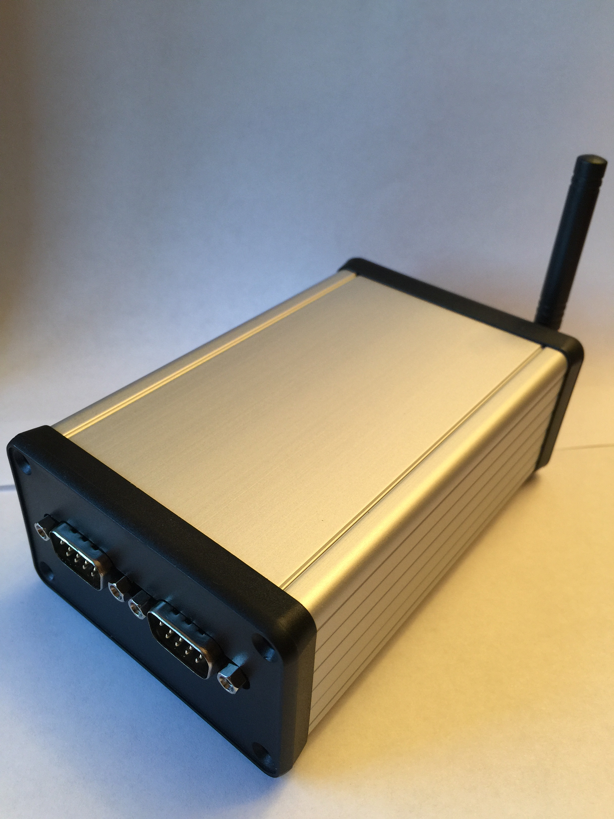
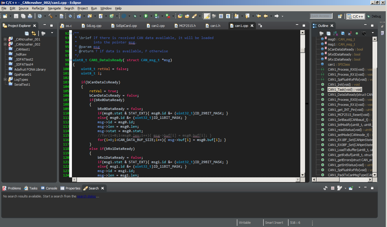
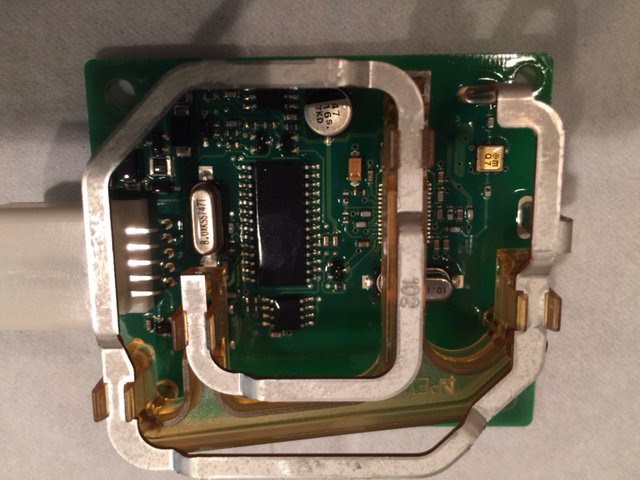
The heart of the CANcrusher is the Freescale MK20DX256 ARM Cortex M4 running at 96MHz. It has 256KB of Flash, 64K of RAM, and 2K of EEPROM that make this a more-than-capable processor to handle the job. While my development is all in Eclipse using the ARM gcc compiler and a makefile, the libraries and support for the processor is all relying on Paul Stoffregen's Teensyduino library of files which allow me to quickly develop the service and application layer functionality without having to reinvent a SPI, USART, or GPIO driver.

My original thought was to use the built-in CAN peripheral of the processor and did build a prototype which uses it, but for the CANcrusher to be useful for hacking and development of a variety of vehicles and applications, it needed multiple flavors of stand-alone CAN channels. For this I turned to the Microchip MCP2515 CAN processor which fully implements the CAN 2.0B standard and communicates with the main controller via a SPI bus at 10MHz.

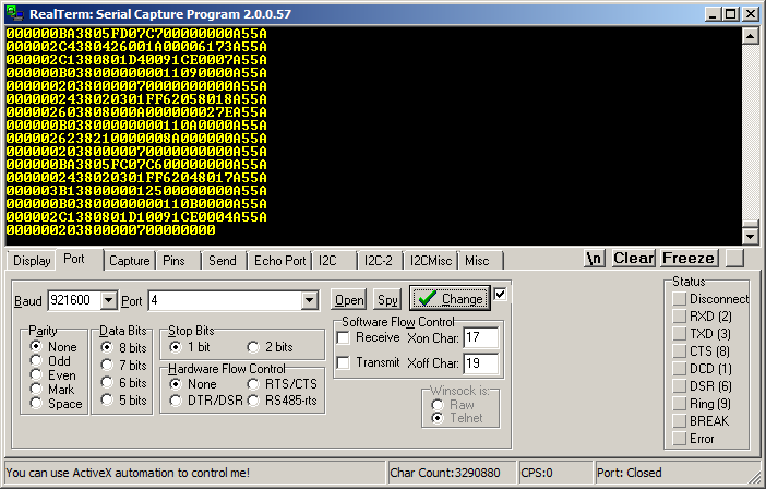
For USB communication, I really like Paul's RawHID driver and the fact that it can enumerate on a host machine without the need for any complicated driver installation. Unless I bump up against a bandwidth limitation, the RawHID driver will continue to be the main pipe to get data to and from the user. On the computer-side, I've written (and am writing) a variety of tools to support the device in Java using the Java HID API which is a JNI wrapper around a C/C++ implementation of the driver. (https://code.google.com/p/javahidapi/)

While USB is the main COM protocol for in-the-car analysis and hacking, I wanted a couple other channels to work with so I added a GSM module from IteadStudio (Model: IM141125004) for remote access and an RN42 Bluetooth radio which allows data rates up to 1Mbit and beyond. (Note on Bluetooth: Why didn't I choose a BTLE radio that would allow easy support for iPhones and iPad app development? BTLE doesn't allow the bandwidth of the RN42. While BTLE struggle to achieve even 1Kb/s, the RN42 will allow up to 300kb/s using it's built-in SPP protocol. So, for now, I've limited the CANcrusher to Android. Although iOS doesn't support SPP, OSX on my Macbook is able to communicate with the CANcrusher just fine.)

The GSM radio is based on the SIM808 which also includes GPS. This saves me the trouble of incorporating a standalone GPS module and so far, works very well. I chose the SIM808, like I choose the Teensy 3.1, because there is a ton of information out there on how to use it.

HARDWARE FEATURES:

  • 3 independent CAN channels supporting DW-CAN, SW-CAN, and LSFT CAN based on the MCP2515 CAN controller.
  • 1 LIN/KLINE channel
  • Bluetooth radio (RN42) with built-in SPP (acts like a serial port)
  • SIM808 GSM / GPS Radio
  • USB
  • SD Datalogging using Bill Greiman's SDfat library for up to 64GB cards
  • Real time clock using the DS3231 high precision RTC
  • Teensy 3.1 (ARM Cortex M4) running @ 96MHz
  • 8 Multi-purpose Inputs and Outputs for directly interfacing with the vehicle (outputs are open collector negative outputs with optional pull-up resistors.)
  • LED Indicators (4 LEDs)


SOFTWARE:

The firmware, as discussed, is Arduino compatible and uses many of the libraries people know and love/hate. Planning to use the GNU General Public License on the firmware and any software created.

On the computer-side, the initial software will be developed in Java with some of the following goals (some early versions of these features is done already):

  • USB or Bluetooth communication with the CANcrusher
  • CAN bus monitor allowing sending and receiving data, processing, reverse engineering, etc...
  • Accepts CAN databases (*.dbc) format
  • Imports and exports log files in Vector and Intrepid Controls Systems format

Why CANcrusher?

As an embedded engineer in the automotive world, I have used the high $$$$ systems and they're great! But they're expensive... There were times that I wanted to have a low-cost system that I could code myself and was inexpensive enough that I could leave in a customer's trunk to monitor my product...

Read more »

  • 1 × Teensy 3.1 Main processor for the device
  • 1 × MCP2515 CAN controller
  • 1 × SN65HVD230 CAN tranceiver
  • 1 × SN65HVDA195 LIN/KLINE transciever
  • 1 × TH8056KDC-AAA SWCAN transceiver

View all 10 components

  • Hacking RF with the CANcrusher

    David09/10/2015 at 10:22 0 comments

    I needed a fun way to test the LIN/KLINE channel with the CANcrusher (and an excuse to hack something) so I guessed that the RF receiver in my 2009 Pontiac Vibe would be using a LIN COM channel to talk with the BCM. (I was close.) Looking at the service manual for my car, I can see that there are only 5 pins with just 4 connections on the "Remote Control Door Lock Receiver (RCDLR)" module.

    1. GND

    2. Serial Data

    3. Keyless Entry Program Enable Signal

    4. NA

    5. Battery Positive Voltage

    This particular module, made by a company called TRW, uses a single wire serial connection which I was hoping was some type of LIN or K-LINE protocol. As it turns out, after connecting to my Picoscope, the data appears to be using a simple USART protocol, 8 bits, 1 start bit, no parity, 2 stop bits, 2400 baud. The nominal voltage on the line is 12V and the data appears to be only 1-direction, from RCDLR to the BCM. When you press a button on a learned keyfob, the serial data will start spitting out repeated 5-byte frames which I assume is the message for a specific button being pressed and held. When you release the button, a single, different frame is sent with some of the bytes only changing by 1 bit, indicating the release. At the beginning of the data stream, there is a 2-byte frame (0xF1, 0x10) which is some type of indicator message sent at the beginning of all data sequences.

    Encrypted Data?....

    At first I was expecting some type of encryption of the data but I'm not so sure anymore. The Service Manual says that this module can store up to 4 unique keys. When you press and release a button, you might get the following sequence:

    F1 10 .... 54 02 00 1B 93 ... 54 02 00 1B 93 ... 54 02 00 1B 93 ...

    Then when you release and press the button a second time you get:

    F1 10 .... 54 02 00 03 AB ... (only 2 bytes change)

    followed by:

    F1 10 .... 54 02 00 0B A3 ... followed by

    F1 10 .... 54 02 00 13 9B ...

    After that, the sequence repeats. There are only 4 unique frames for that button being pressed and the sequence repeats in order. Hackable? Yes!

    What's Next:

    As you saw from the previous post, one of my prototypes died. Once I get prototype 2 up and running, I'll connect to the serial data line of this module using the LIN transceiver and mimic the data sent by this module to the BCM to control my door locks and panic button. From there, I'll be able to remotely control this feature via Bluetooth and through the SIM808 cell module from my server.

    For those interested, this particular module uses an Infineon ASK 315MHz transceiver (TDA5201) and a Microchip PIC16F76 8-bit controller. If the protocol wasn't as straight forward as it was on the serial line, next steps would be to attempt to dump the binary image from the PIC. (Note: I can't imagine TRW would have left the fuse unlocked that would allow me to do that, but one should always try. ;)


  • Crap... When Things Go Wrong...

    David09/10/2015 at 09:45 0 comments

    One of my prototypes, ok, my main prototype, died a painful death on Monday. Something shorted 3.3V to GND and I couldn't figure out what it was. Typically when this type of thing happens, you start removing the likely components and replace them. I tried doing this, yet each time I removed a component, the short was still there. Long story short, I removed EVERY component and the short is still there. I cleaned the PCB, solder wicked all the excess solder and it still remains. I have a USB microscope on order so I can take a look at the board and see what's up. In the mean time, I do have a second prototype and will continue down the path as soon as I'm able. For those monitoring the progress of the project, sorry for the delay.

  • Added a "Static View" to Streaming CANbus Data

    David08/22/2015 at 10:54 0 comments

    CANbus hacking made more simple... In addition to the scrolling CANbus data (the Matrix), I created a "static view" of the data in which all messages with the same Arbitration ID overlay each other in the same row so you can identify what data is changing and what is staying the same. To draw your eye to the changing data, a highlighting feature was added that will highlight in yellow and bold any bytes that are changing...


  • CANbus Data is Streaming!...

    David08/21/2015 at 01:13 0 comments

    The software is moving along. Created some interfaces to parse the streaming USB RawHID data into CANbus messages for display in a scrolling table. Next steps is to add some different views such as capturing duplicate ARB IDs and overlaying the data on the same row to discover what data is changing and what data is staying the same. (Sneek Preview: Going to add a new feature called the "Mimic Interface" which will allow you to grab any of the existing messages, select which bits you want to set as a certain value and then the Mimic tool will grab all incoming messages with the same ID, change only the bits you want, and spit the new modified data back onto the bus immediately allowing you to mimic the ECU that is generating that message with your own custom data.)


  • USB Interface Working

    David08/16/2015 at 16:22 0 comments

    I reworked the communication interface this weekend and got it to a fairly useful state. This same protocol will be used for USB and Bluetooth communication for interfacing to the diagnostic application. I created a RawHID USB Monitor for verifying the data traffic. Check out the CANcrusher Into video here to see it working on my car.


  • ViaCAD and Hammond Mfg

    David08/15/2015 at 22:27 0 comments

    Hammond Manufacturing has been nice to use for the CANcrusher enclosure. The original box I chose was only going to be 1" thick, but I quickly ran out of vertical room and needed to upgrade (of course, this was after my board layout...) Thankfully, they had a direct replacement with the same L and W but with an extra .7" height for the design. In addition, they provide solid models for planning bezel layout and overall electronic placement. I used ViaCAD to design my enclosure layout and for exporting to MeshCAM to generate the gcode for the Shapeoko.

  • Cutting the bezels

    David08/15/2015 at 11:12 0 comments

    I finally got to use my Shapeoko for what I bought it for... Electronic project box bezels... Here's a pic of it cutting out the DB9 connectors.

  • Early Source Code added...

    David08/15/2015 at 10:21 0 comments

    Added some early code to the repository. Development is moving quickly so I hope to have some significant changes in the coming weeks. Check out https://github.com/afterhoursengineering/_CANcrusher_ARM

  • Project logs before sleep... I have issues...

    David08/15/2015 at 09:27 0 comments

    Worked through some of the major software architecture "snakes" this week. I have the basis of a communication protocol between the CANcrusher and the computer/tablet/whatever whether it's via USB or bluetooth. One of the hurdles I wanted to deal with was how to buffer the transmitted data, how much to buffer, etc. When CAN messages are flowing into the stream in 170-200us bursts and there are multiple CAN channels being monitored and sent off or logged, some of the packets have to be buffered. Since I'm using RawHID for the USB interface, I'm limited to 64 byte frames. I like using circular buffers for this type of thing, but I didn't want a single big buffer of all the frame bytes mashed into a single holding array and I didn't want some kind of rolling buffer of arrays. Instead I ended implementing a circular buffer of array pointers, addresses to the head and tail buffers. This seems to work well. The goal (crazy as it sounds) is to have the basic structure of this concept working this weekend and implemented on both a simple Java app and in the CANcrusher. We'll see how it goes...

  • As of 8/13/2015...

    David08/13/2015 at 10:47 0 comments

    • MCP2515 Drivers are done
    • External IO functional
    • Port Expanders and driver complete
    • Bluetooth communication - complete
    • SIM808 Driver - complete for GPS data parsing.
    • SD logging - complete

    I've tested the system on my car and am able to log HSCAN data at 500k rates. GPS is functional. Basic software is complete for extracting the binary log files and exporting to *.csv and Vector/Intrepid log file formats.

    TODO: More then I'd like, but the list is shrinking!!

View all 10 project logs

Enjoy this project?

Share

Discussions

edizius wrote 11/22/2016 at 20:00 point

Hi there. Is there any process happening to this project? Are the schematics and the software etc. public? If not, can it be bought (already)? What is the price/will be the price?

  Are you sure? yes | no

Piotr wrote 08/26/2015 at 08:23 point

Take a look at BusMaster software developed by ETAS and Bosch. It's Open Source and could save you a good part of work with software - e.g. it already has Vector file formats support.

  Are you sure? yes | no

David wrote 08/26/2015 at 09:48 point

Wow! That's a very nice SW package as Open Source projects go (even if it had a cost associated with it, still nice).  Thanks for the tip.  It gives me something to think about.  Thinking out loud... I'd have to rewrite the USB portion of the firmware to possibly work with one of the existing drivers the Busmaster uses.  Feasible..  One downside of the Busmaster package is it's dependence on Windows.  This isn't really a problem for me (I use Windows and OSX and Linux) but I was hoping to launch this thing with some platform independent software, hence the Java development.  However, that's why I open-sourced the code, to allow anyone to do with this whatever they wanted. 

  Are you sure? yes | no

Piotr wrote 08/27/2015 at 08:44 point

I recommended Busmaster because we sometimes use it as a replacement for Vector tools. 

Regarding the driver - you could either rewrite the device communication protocol or write an interface for the Busmaster. It's extensible and API is available as far as I know, as are the sources for other drivers it uses. We wanted to write a driver for other USB-CAN interface (http://www.mictronics.de/projects/usb-can-bus/) for Busmaster, but none of us (me and my team colleagues) have either experience or time to write it... It is doable though.

I noticed that you stream messages in ASCII format to the PC. The USB-CAN interface I mentioned does the same... Maybe the driver could support both?

  Are you sure? yes | no

Yann wrote 08/26/2015 at 06:36 point

Very nice project. Do you plan to sell the complete package or at least the SMD populated PCB ?

  Are you sure? yes | no

David wrote 08/26/2015 at 09:55 point

Yes.  Still working through some of the manufacturing costs, but my hope is to get this into people's hands without the need for them to buy all the components and go through the hours and hours of hand-soldering one themselves.  Stay tuned...

  Are you sure? yes | no

dougal wrote 08/26/2015 at 13:44 point

Do you have any estimate (ballpark) of what you think the final cost will be? Is there any thought of a "lite" version, where the GSM and/or BT are optional? I'm looking forward to seeing what this sucker can do!

  Are you sure? yes | no

Daniel S. wrote 08/26/2015 at 06:07 point

I love this. At work I use a system that rhymes with Manalyzer by a company that rhymes with Hector. I want to get a system for myself because as you said, the $$$$ systems are nice! But it's far too many $$$$ for hobbyist use. This looks awesome and I'm familiar with all the hardware you used. Can't wait to build one of these.

Can you recommend an open source and/or free beer dbc editor? Or do you plan on developing something yourself?

  Are you sure? yes | no

Piotr wrote 08/26/2015 at 08:24 point

Take a look at BusMaster software developed by ETAS and Bosch.

Disclaimer: I'm not affiliated with the software developers; just using it in my lab environment.

  Are you sure? yes | no

David wrote 08/26/2015 at 10:05 point

I'm in the same boat.  I use the system that rhymes with Manalyzer and I have also used the systems that rhyme with MeoVi.  They are both awesome CAN tools and the software is excellent.  But I don't have a multi-million dollar contract to build an ECU for an OEM or the desire to spend the money for a Manalyzer or MeoVi.  I just want to play with the CANbus on my cars (and maybe some other people's cars ;)...  Regarding the DBC editor, I don't have any immediate plans to develop one, but I may try to incorporate dbc importing to the software if you have one already.  I took Peotr's advice and looked at the Busmaster software and it looks like it has a dbc editing feature.  Maybe I'll add the ability to import it.  We'll see.. I'm still working through re-inventing the wheel with my Java-UI.   

  Are you sure? yes | no

Similar Projects

Does this project spark your interest?

Become a member to follow this project and never miss any updates